Wash Basin
YOSHIZAWA; Yoshihiro ; et al.
U.S. patent application number 16/466626 was filed with the patent office on 2019-10-10 for wash basin. This patent application is currently assigned to LIXIL Corporation. The applicant listed for this patent is LIXIL Corporation. Invention is credited to Tsutomu KOJIMA, Mamoru SAIDA, Yoshihiro YOSHIZAWA.
| Application Number | 20190309504 16/466626 |
| Document ID | / |
| Family ID | 62491889 |
| Filed Date | 2019-10-10 |
| United States Patent Application | 20190309504 |
| Kind Code | A1 |
| YOSHIZAWA; Yoshihiro ; et al. | October 10, 2019 |
WASH BASIN
Abstract
A wash basin includes a wash bowl portion and an outer lateral portion that is connected to an outer peripheral portion of the wash bowl portion and has a lower end portion mounted on the supporting member. On a lower surface side of the wash bowl portion, each of recessed grooves is formed in a connecting portion between an outer peripheral surface of the outer lateral portion and the wash bowl portion.
| Inventors: | YOSHIZAWA; Yoshihiro; (Tokyo, JP) ; SAIDA; Mamoru; (Tokyo, JP) ; KOJIMA; Tsutomu; (Tokyo, JP) | ||||||||||
| Applicant: |
|
||||||||||
|---|---|---|---|---|---|---|---|---|---|---|---|
| Assignee: | LIXIL Corporation Tokyo JP |
||||||||||
| Family ID: | 62491889 | ||||||||||
| Appl. No.: | 16/466626 | ||||||||||
| Filed: | December 1, 2017 | ||||||||||
| PCT Filed: | December 1, 2017 | ||||||||||
| PCT NO: | PCT/JP2017/043333 | ||||||||||
| 371 Date: | June 4, 2019 |
| Current U.S. Class: | 1/1 |
| Current CPC Class: | A47K 1/04 20130101; E03C 1/33 20130101; E03C 1/18 20130101; E03C 1/14 20130101 |
| International Class: | E03C 1/33 20060101 E03C001/33 |
Foreign Application Data
| Date | Code | Application Number |
|---|---|---|
| Dec 6, 2016 | JP | 2016-237151 |
Claims
1. A wash basin that is provided on a supporting member in a state where a peripheral edge portion of the wash basin is mounted on the supporting member, the wash basin comprising: a wash bowl portion; and an outer lateral portion that is connected to an outer peripheral portion of the wash bowl portion and has a lower end portion being mounted on the supporting member, wherein on a lower surface side of the wash bowl portion, a recessed portion is formed in at least a part of a connecting portion between an outer peripheral surface of the outer lateral portion and the wash bowl portion.
2. The wash of claim 1, wherein the recessed portion is formed in at least a boundary portion between a mounting portion provided in a water faucet attaching portion connected to the outer peripheral portion of the wash bowl portion and the wash bowl portion.
3. The wash basin of claim 1, wherein the recessed portion has curved surfaces formed in at least the wash bowl portion and a portion connected to the outer peripheral portion of the wash bowl portion.
4. The wash basin of claim 1, wherein a curvature radius of a corner portion that connects adjacent inner surfaces of the wasbowl portion to each other is set to 30 mm or larger and 35 mm or smaller.
5. The wash basin of claim 2, wherein the recessed portion has curved surfaces formed in at least the wash bowl portion and a portion connected to the outer peripheral portion of the wash bowl portion.
6. The wash basin of claim 2, wherein a curvature radius of a corner portion that connects adjacent inner surfaces of the wash bowl portion to each other is set to 30 mm or larger and 35 mm or smaller.
7. The wash basin of claim 3, wherein a curvature radius of a corner portion that connects adjacent inner surfaces of the wash bowl portion to each other is set to 30 mm or larger and 35 mm or smaller.
8. The wash basin of claim 5, wherein a curvature radius of a corner portion that connects adjacent inner surfaces of the wash bowl portion to each other is set to 30 mm or larger and 35 mm or smaller.
Description
CROSS-REFERENCE TO RELATED APPLICATIONS
[0001] This application is a national stage patent application under 35 U.S.C. 371 of International Application No. PCT/JP2017/043333, filed Dec. 1, 2017, which claims the priority of Japanese Application No. 2016-237151, filed Dec. 6, 2016, the entire contents of each of which are incorporated herein by reference.
FIELD OF THE INVENTION
[0002] The present invention relates to a wash basin.
BACKGROUND OF THE INVENTION
[0003] In the related art, for example, a wash-basin shown in such as Patent Document 1 is known as a vessel-type wash-basin, which is provided in a state where a peripheral edge portion thereof is mounted on the supporting member such as a counter. The wash-basin of Patent Document 1 includes a wash bowl portion and an outer lateral portion which is connected to an outer peripheral portion of the wash bowl portion and of which a lower end portion is mounted on a supporting member.
[0004] In such a ceramic wash basin, stress distribution is achieved by making a curvature radius of a corner portion in the wash bowl portion large as a measure against heat shock, which causes breakage attributable to the occurrence of thermal contraction in a case where a temperature of the wash bowl portion is low by putting hot water into the wash bowl portion or a measure against fragmenting at the time of firing in a manufacturing process.
[0005] Patent Document 1: Japanese Unexamined Patent Application, First Publication No. 2005-87647
SUMMARY OF THE INVENTION
[0006] However, although the curvature radius of the corner portion in the wash bowl portion described above is made large as the measure against breakage attributable to heat shock or the measure against fragmenting at the time of firing in the ceramic wash basin described above, an inner surface of the outer lateral portion overhangs to an inner side as the curvature radius increases. Thus, there is a problem of a volume of the wash bowl portion becoming small.
[0007] In addition, there are many cases in which the design of a wash basin is required to look sharp in recent years. However, by making the curvature radius of the corner portion in the wash bowl portion large in plan view, which is seen from above, the outer lateral portion, in particular, does not look sharp, and thus an appearance of the entire wash basin aggravates.
[0008] The present invention is devised in view of the problems described above, and an object thereof is to provide a wash basin that can prevent fragmenting at the time of firing and breakage of ceramics attributable to heat shock, can make the capacity of a wash bowl portion large, and can have a sharp appearance.
[0009] In some embodiments, there is provided a wash basin that is provided on a supporting member in a state where a peripheral edge portion of the wash-basin is mounted on the supporting member. The wash basin includes a wash bowl portion and an outer lateral portion that is connected to an outer peripheral portion of the wash bowl portion and has a lower end portion being mounted on the supporting member. On a lower surface side of the wash bowl portion, a recessed portion is formed in at least a part of a connecting portion between an outer peripheral surface of the outer lateral portion and the wash bowl portion.
[0010] In some embodiments, since stress is distributed by the recessed portion formed in at least a part of the connecting portion between the outer peripheral surface of the outer lateral portion and the wash bowl portion, stress concentration is capable of being limited to be low. For this reason, fragmenting at the time of firing and breakage of ceramics attributable to heat shock is capable of being prevented.
[0011] Unlike the related art, it is not necessary to make the curvature radius of the corner portion in the wash bowl portion large in the present invention, and it is possible to make a volume of the wash bowl portion large. Since the corner portion in the wash bowl portion has a shape having a small curvature radius, the appearance is capable of being made sharp.
[0012] In some embodiments, the recessed portion may be formed in at least a boundary portion between a mounting portion provided in a water faucet attaching portion connected to the outer peripheral portion of the wash bowl portion and the wash bowl portion.
[0013] In some embodiments, since the recessed portion is formed in the boundary portion between the mounting portion of the water faucet attaching portion and the wash bowl portion, stress is capable of being effectively distributed in the water faucet attaching portion of which shape is complicated and which is likely to be broken as a result of stress concentration.
[0014] In some embodiments, the recessed portion may have curved surfaces formed in at least a portion connected to the wash bowl portion and a portion connected to the outer peripheral portion of the wash bowl portion.
[0015] In this case, since the outer lateral portion is connected to the outer peripheral portion of the wash bowl portion via the curved surfaces of the recessed portion and a corner portion is not formed in the recessed portion, stress concentration in the boundary portion between the wash bowl portion and the mounting portion is capable of being more effectively limited.
[0016] In some embodiments, a curvature radius of a corner portion that connects adjacent inner surfaces of the wash bowl portion to each other may be set to 30 mm or larger and 35 mm or smaller.
[0017] In some embodiments, by making the curvature radius of the corner portion in the wash bowl portion large, for example, 30 mm or larger and 35 mm or smaller, in addition to providing the recessed portion, stress is capable of being more reliably distributed. Therefore, fragmenting at the time of firing and breakage of ceramics attributable to heat shock is capable of being prevented.
[0018] In some embodiments, fragmenting at the time of firing and breakage of ceramics attributable to heat shock can be prevented. In addition, the capacity of the wash bowl portion can be made large, and an appearance can be made sharp.
BRIEF DESCRIPTION OF THE DRAWINGS
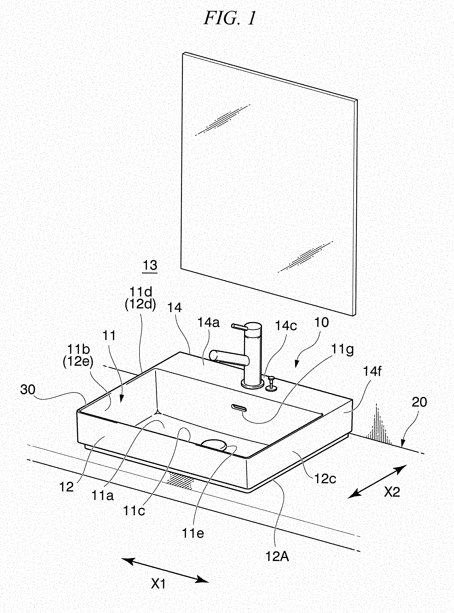
[0019] FIG. 1 is a perspective view showing a state where a wash basin according to some embodiments is provided on a supporting member;
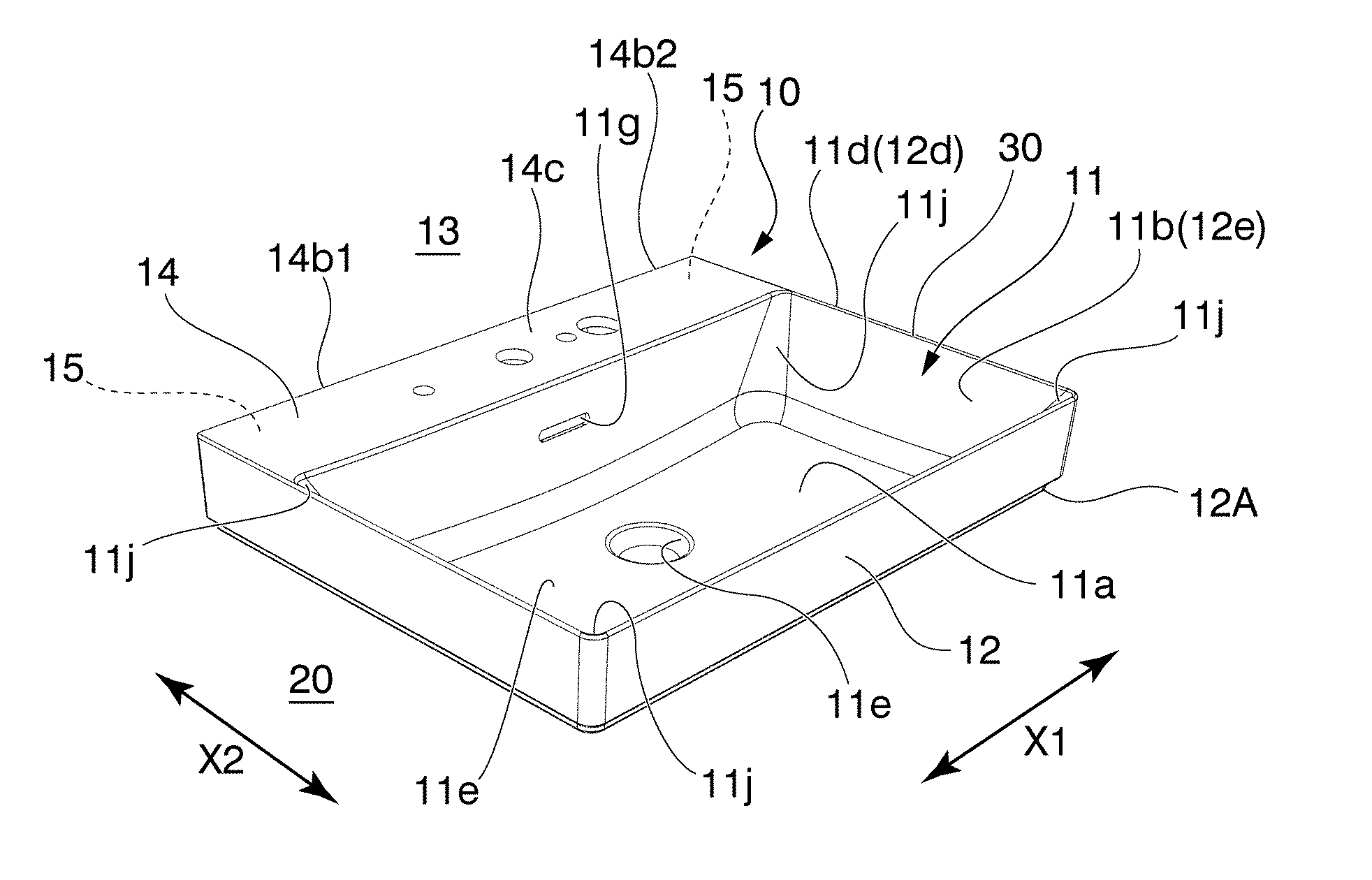
[0020] FIG. 2 is a perspective view showing an entire structure of the wash basin shown in FIG. 1, according to some embodiments;
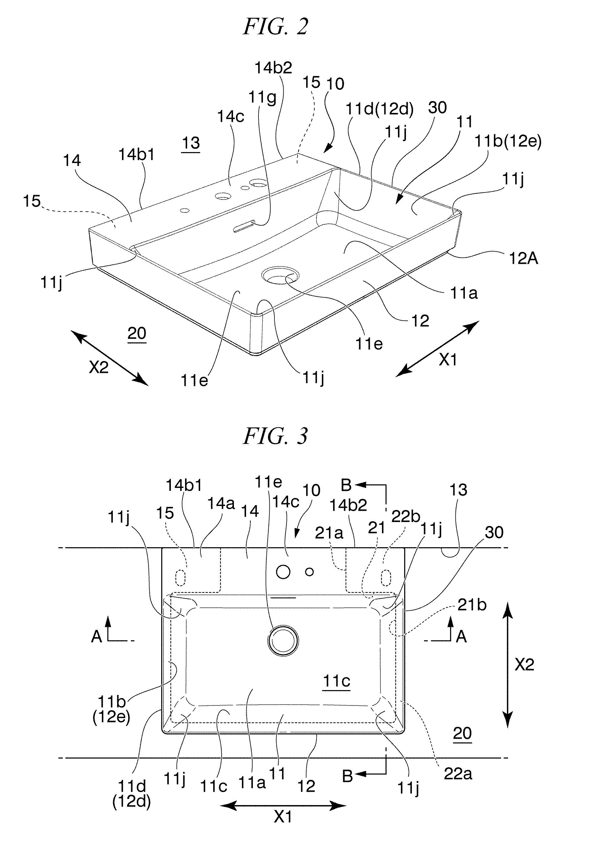
[0021] FIG. 3 is a plan view of the wash basin shown in FIG. 2, according to some embodiments;
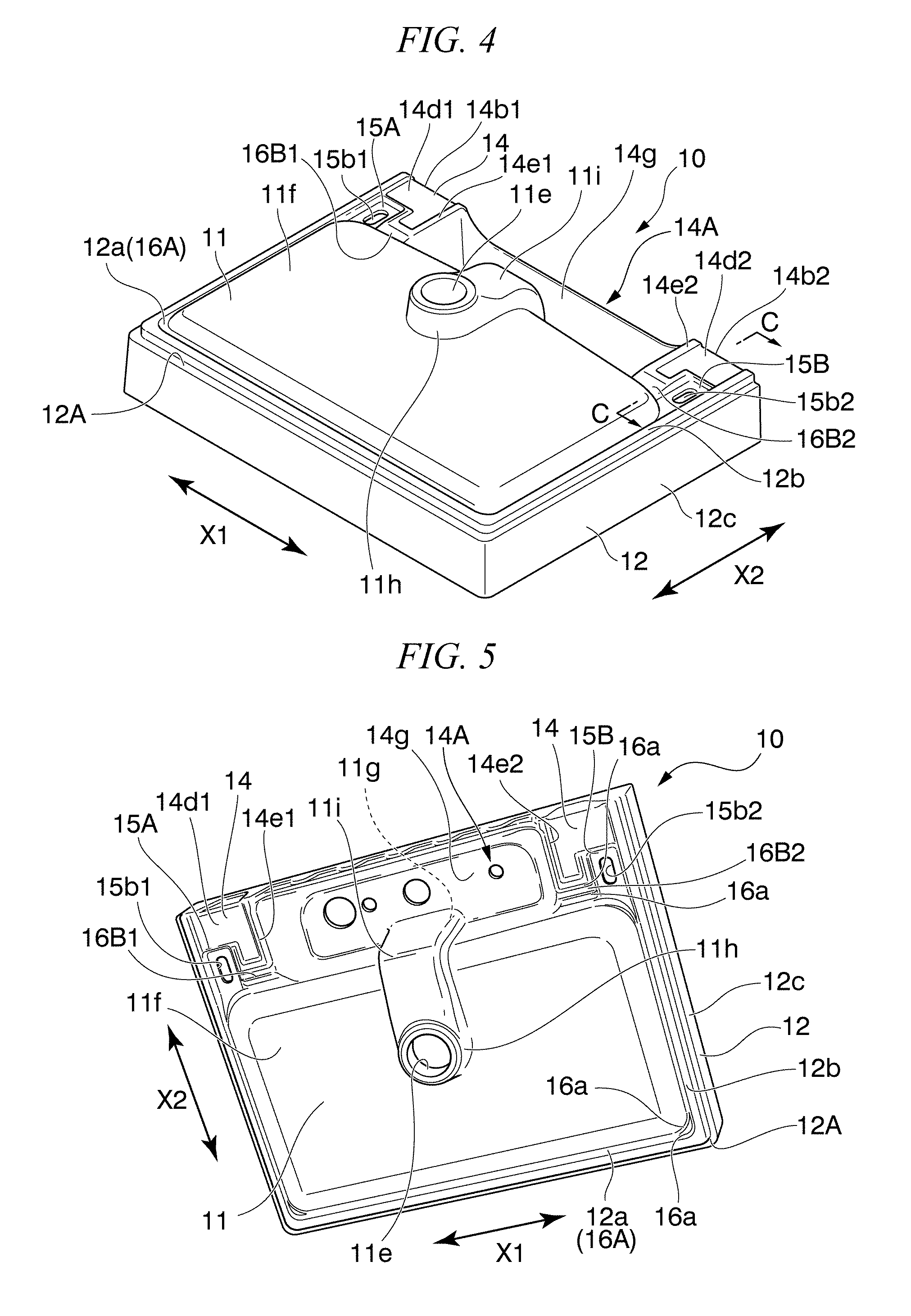
[0022] FIG. 4 is a perspective view showing a bottom surface structure of the wash basin shown in FIG. 1, according to some embodiments;
[0023] FIG. 5 is a perspective view showing the bottom surface structure of the wash basin shown in FIG. 1, and is a view seen from an angle different from FIG. 4, according to some embodiments;
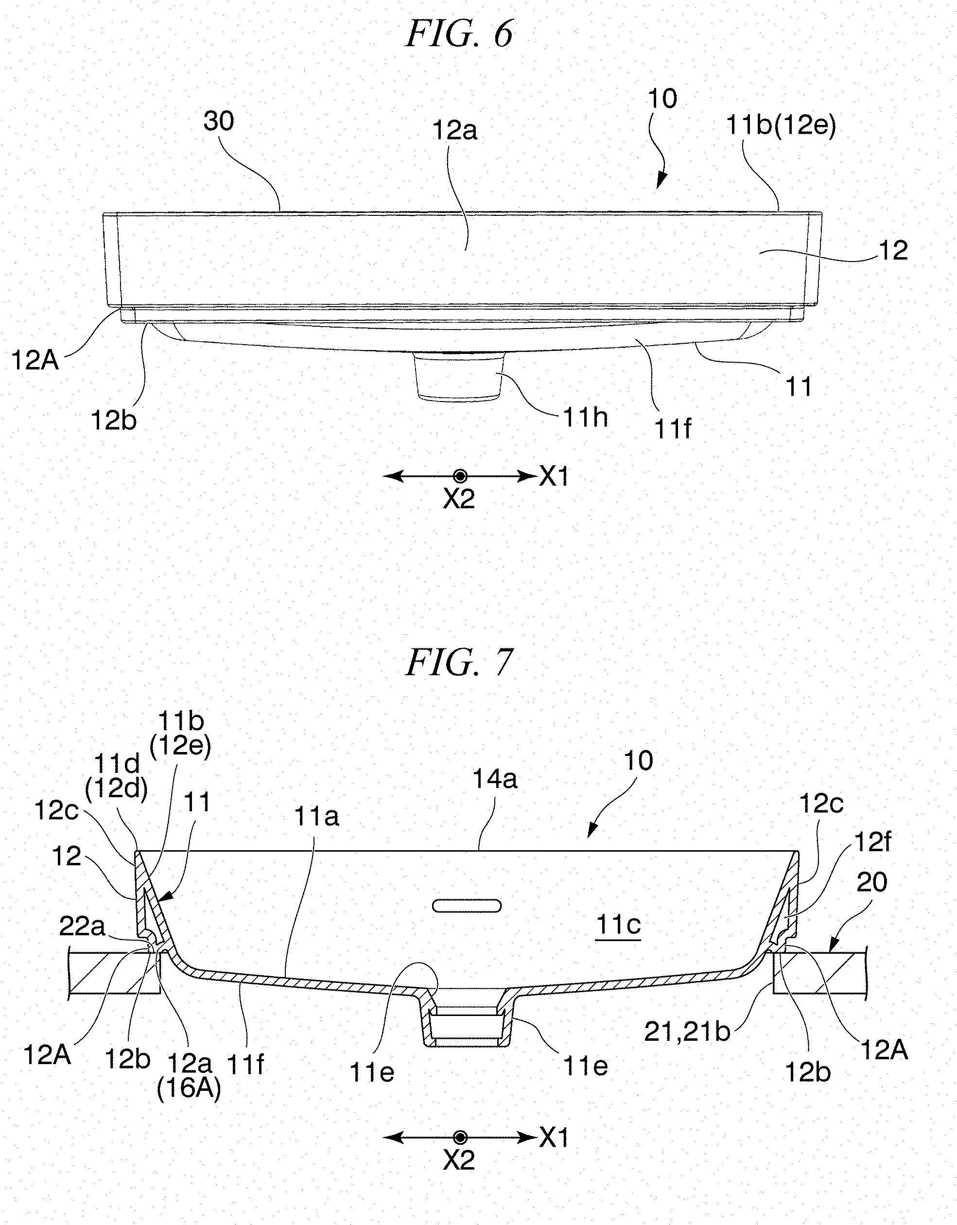
[0024] FIG. 6 is a side view of the wash basin seen from a front side, according to some embodiments;
[0025] FIG. 7 is a sectional view taken along line A-A shown in FIG. 3, according to some embodiments;
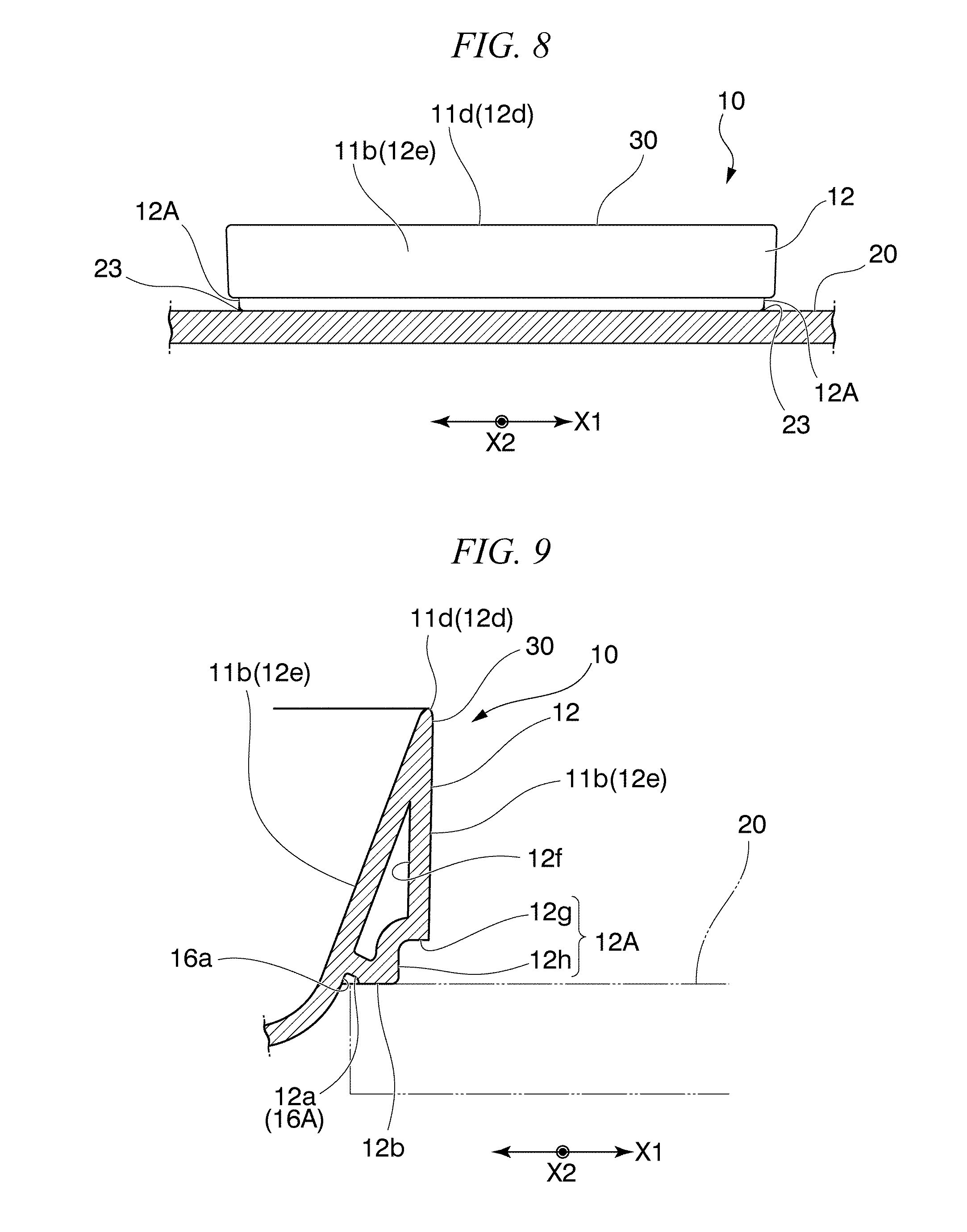
[0026] FIG. 8 is a side view of the wash basin in a state of being provided on the supporting member shown in FIG. 1, which is seen from the front side, according to some embodiments;
[0027] FIG. 9 is a main portion enlarged view showing a configuration of an outer lateral portion shown in FIG. 7, according to some embodiments;
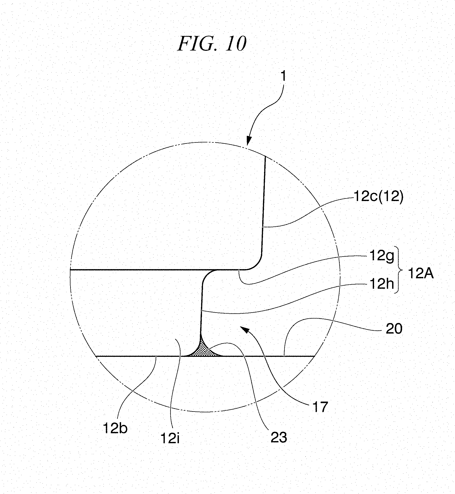
[0028] FIG. 10 is a main portion enlarged view showing a configuration of a step portion of the outer lateral portion shown in FIG. 8, according to some embodiments;
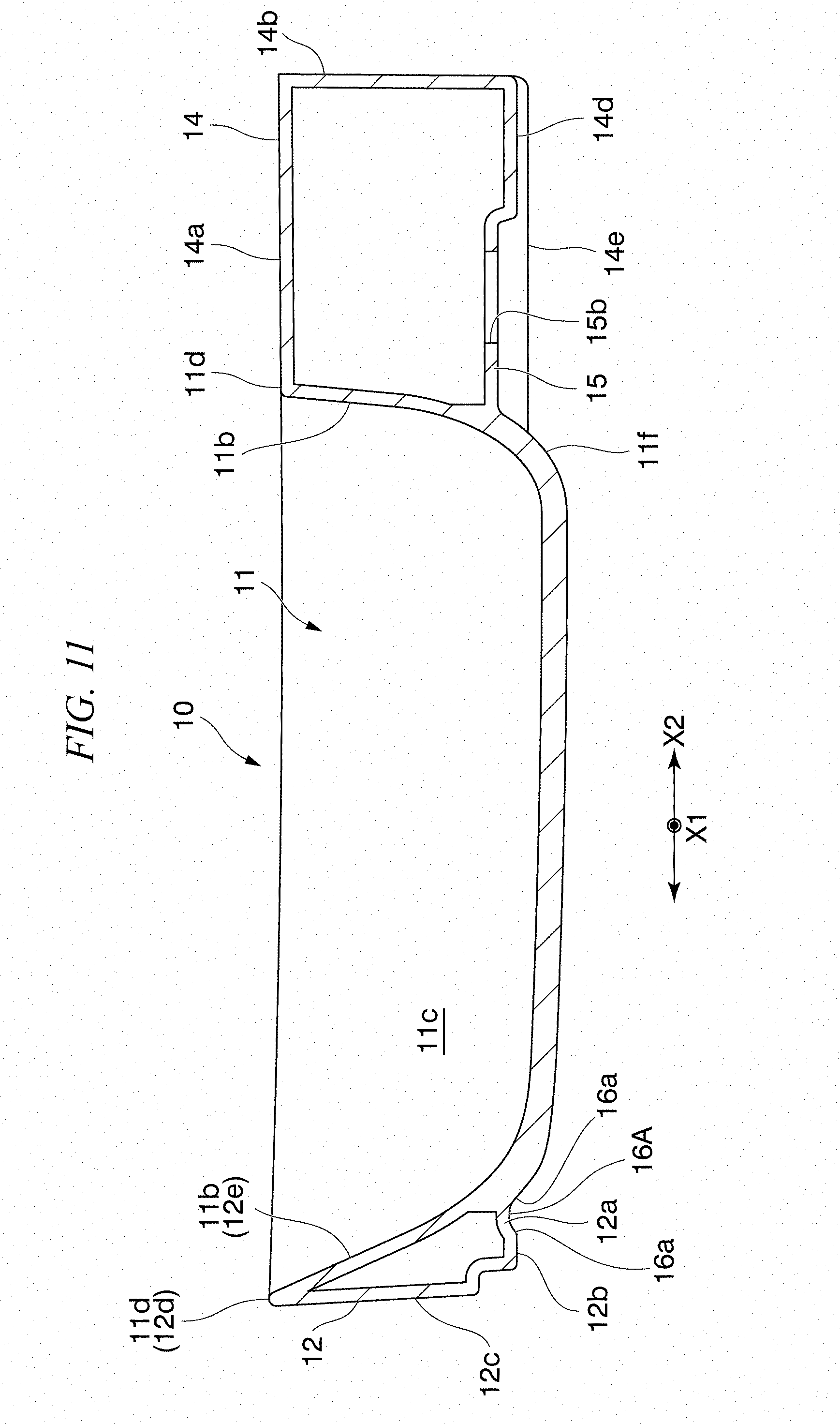
[0029] FIG. 11 is a sectional view taken along line B-B shown in FIG. 3, according to some embodiments;
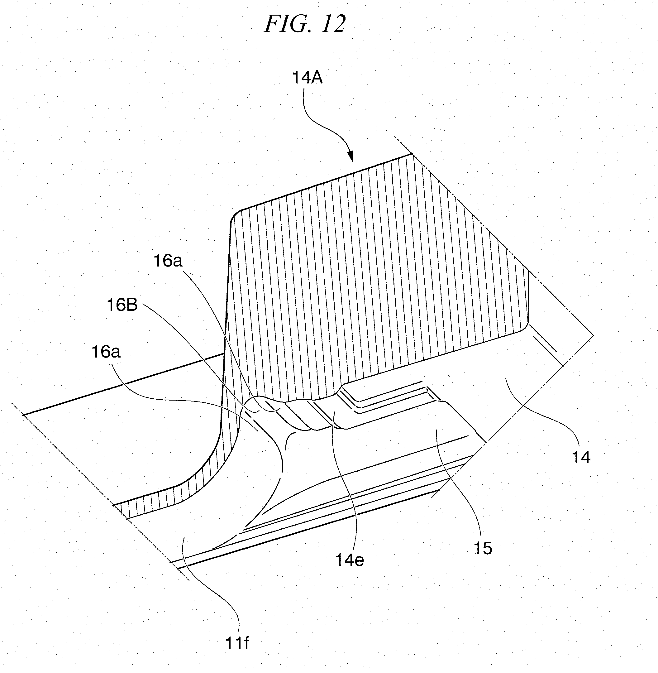
[0030] FIG. 12 is a sectional view taken along line C-C shown in FIG. 4, according to some embodiments;
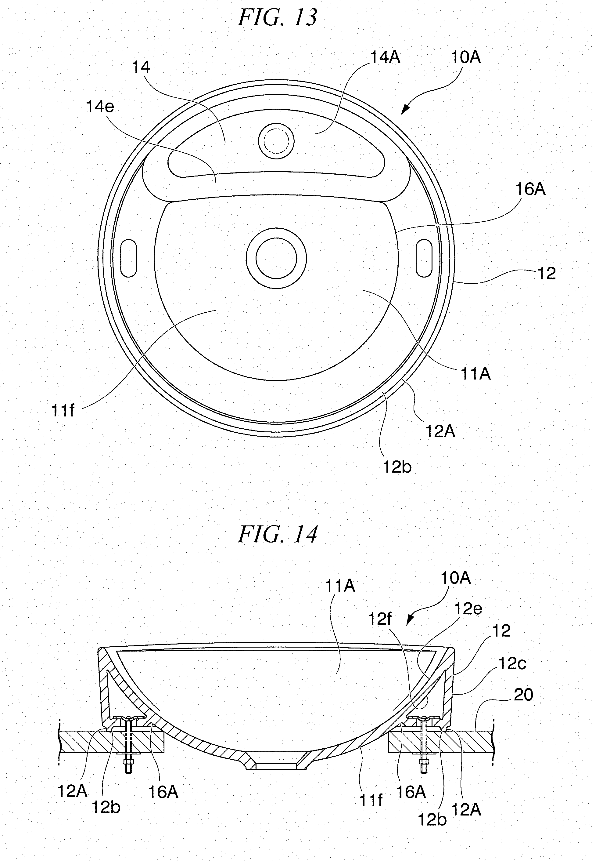
[0031] FIG. 13 is a plan view showing a bottom surface structure of a circular wash basin according to a modification example, according to some embodiments; and
[0032] FIG. 14 is a side sectional view of the circular wash basin according to the modification example, and is a view corresponding to FIG. 7, according to some embodiments.
DETAILED DESCRIPTION OF THE INVENTION
[0033] Hereinafter, a wash basin according to some embodiments of the present invention will be described with reference to the drawings.
[0034] As shown in FIGS. 1 to 3, a wash basin 10 according to some embodiments is configured to be supported by a supporting member 20, which is formed of a counter or the like, in a state where a peripheral edge portion of the wash basin 10 is mounted.
[0035] In some embodiments, when a user is positioned in front of the wash basin 10, a side close to the user will be referred to as a front side, and a side far from the user will be referred to as a back side (opposite side to the front side). A portion which is connected between the front side and the back side of the wash basin 10 will be referred to as the lateral side. In addition, a right-and-left direction when the wash basin 10 is seen from the front side will be referred to as a width direction X1, and a direction of the front side and the back side will be referred to as a front-and-back direction X2.
[0036] The wash basin 10 has a wash bowl portion 11, an outer lateral portion 12 connected to the front side and both lateral sides of the wash bowl portion 11, and a back portion 14 in which fixing portions 15 are formed. The fixing portions 15 are provided on the back side (that is, a wall 13 side on which a mirror, a cabinet, or the like is disposed) of the wash bowl portion 11, and are fixed to the supporting member 20. The wash-basin 10 is made of ceramics, and the wash bowl portion 11, the outer lateral portion 12, and the back portion 14 are integrally formed.
[0037] The wash bowl portion 11 is formed in a substantially quadrangular shape in plan view. In addition, as shown in FIG. 2, the wash bowl portion 11 is formed in a recessed shape in which a bottom surface portion 11a and a peripheral edge portion 11b are continuously formed, and an inner surface 11c of the wash bowl portion 11 continues therefrom. The peripheral edge portion 11b is formed to rise steeply in four directions, and a top portion 11d of the peripheral edge portion 11b is continuously formed at a substantially fixed height and in an annular shape.
[0038] A drain port 11e is formed in the bottom surface portion 11a, and the bottom surface portion is formed in a downward slope from the peripheral edge portion 11b to the drain port 11e. An overflow hole 11g is formed in a middle portion in the width direction X1 on the back side of the inner surface 11c of the wash bowl portion 11.
[0039] As shown in FIG. 5, a drainage path 11h is formed in the drain port 11e of the bottom surface portion 11a of the wash bowl portion 11. An overflow flow path 11i extending from the overflow hole 11g is connected to the drainage path 11h.
[0040] In the wash-basin 10, ceramic surface of the wash bowl portion 11, ceramic surface of the outer lateral portion 12, and ceramic surface of the back portion 14 are covered with glaze. In some embodiments, in the wash bowl portion 11, all inner surfaces of respective the drain port 11e, the overflow hole 11g, the drainage path 11h, and the overflow flow path 11i are also covered with glaze. An upper part of the overflow hole 11g in the drainage path 11h is also covered with glaze.
[0041] As an example of a glaze-covering method in this case, a method of closing the drain port 11e and fully filling the overflow flow path from the overflow hole 11g to the drainage path 11h with glaze can be given. Thus, the entire flow path inner surface of the overflow flow path 11i can be covered with glaze.
[0042] As shown in FIGS. 2, 3, and 6, the outer lateral portion 12 is continuously provided on the front side and both lateral sides of the wash bowl portion 11, and configures an edge portion of the wash basin 10. A top portion 12d of the outer lateral portion 12 is configured at the same position as the top portion 11d of the peripheral edge portion 11b of the wash bowl portion 11, and an inner surface 12e of the outer lateral portion 12 is configured at the same position as the peripheral edge portion 11b (the inner surface 11c) of the wash bowl portion 11. As shown in FIG. 1, an outer peripheral surface 12c of the outer lateral portion 12 is formed to be a substantially vertical surface when the wash basin 10 is provided on the supporting member 20. As shown in FIG. 7, a hollow portion 12f is formed between the inner surface 12e and the outer peripheral surface 12c of the outer lateral portion 12. The outer peripheral surface 12c of the outer lateral portion 12 may be formed in a vertical direction, or the outer peripheral surface may have a slope in any one of a direction of approaching a wash bowl portion 11 side with respect to the vertical direction and a direction of separating away from the wash bowl portion 11 side. Each of the inner surface 12e and the outer peripheral surface 12c, which define the hollow portion 12f of the outer lateral portion 12, approaches and abuts against the top portion 12d as going upwards, and thus the entire outer lateral portion 12 is continuously formed.
[0043] Herein, as shown in FIG. 1, a portion configured with the top portion 11d (12d) of the wash bowl portion 11, an upper portion of the peripheral edge portion 11b, and an upper portion of the outer peripheral surface 12c of the outer lateral portion 12, the portion being a peripheral edge of the wash bowl portion 11, corresponds to a rim 30.
[0044] As shown in FIGS. 4, 5, and 7, a connecting portion 12a that is connected and integrated with an outer lateral surface 11f of the wash bowl portion 11 is formed at a lower end of the outer lateral portion 12. A mounting portion 12b to be mounted on the supporting member 20 is formed at the connecting portion 12a. In a state where the mounting portion 12b is mounted on the supporting member 20, the mounting portion 12b is formed as a flat surface protruding slightly downwards from the connecting portion 12a. The mounting portion 12b may be mounted by directly abutting against the supporting member 20, or may be mounted via a packing or caulking agent or the like. The mounting portion 12b may be mounted by forming a recessed portion in an upper surface of the supporting member 20 at a position of opposing the mounting portion 12b and fitting the mounting portion to the recessed portion.
[0045] As shown in FIGS. 6 and 7, in a state where the mounting portion 12b is mounted on the supporting member 20, the outer lateral portion 12 is formed to cover the outer lateral surface 11f such that the outer lateral surface 11f of the wash bowl portion 11 disposed on the supporting member 20 is invisible from the outside. A step portion 12A having a shape, in which a mounting portion 12b side is recessed toward an outer lateral surface 11f side of the wash bowl portion 11 from the outer peripheral surface 12c, is formed in the outer lateral portion 12 at a connection portion 17 between the outer peripheral surface 12c and a peripheral edge 12i of the mounting portion 12b. As shown in FIGS. 8 to 10, the step portion 12A has a step lower surface 12g that opposes the supporting member 20 in a state where the wash basin 10 is mounted on the supporting member 20 and a step side surface 12h that extends upwards from an outer end of the mounting portion 12b and is connected to an inner end of the step lower surface 12g. The step lower surface 12g may be a horizontal surface, or may be an inclined surface of the step portion 12A, which is a downward slope toward the outer lateral surface 11f side of the wash bowl portion 11.
[0046] A caulking-processed portion 23 to which a caulking material for stopping water, such as silicone, is applied is provided in a boundary portion between the step side surface 12h of the step portion 12A and the supporting member 20. Since the boundary portion between the step side surface 12h and the supporting member 20, and the step side surface 12h are at positions on the back of the outer peripheral surface 12c of the outer lateral portion 12, and are generally positioned below a user's line of sight, who uses the wash basin, the boundary portion and the step side surface are parts that are hidden and inconspicuous. That is, also the caulking-processed portion 23 provided in the boundary portion is a portion that is unlikely to be seen by the user.
[0047] Caulking-treatment is applied on the step portion 12A between the peripheral edge 12i of the mounting portion 12b and the supporting member 20.
[0048] A dimension of a recess of the step portion 12A (a depth dimension of the step lower surface 12g and a height of the step side surface 12h) is set to a size that allows, for example, a finger, a spatula, or the like to be put in between the supporting member 20 and the peripheral edge, the size allowing caulking work of finishing a caulking material applied by a finger or the like. The depth of the step lower surface 12g can be set to, for example, 10 mm, and the height of the step side surface 12h can be set to 15 mm (at least 13 mm).
[0049] In some embodiments, the mounting portion 12b is narrowly formed to be continuous on the front side and both lateral sides of the wash bowl portion 11 along the outer lateral portion 12. Herein, a width of the mounting portion 12b is set to, for example, 15 mm or lower.
[0050] As shown in FIG. 2 to FIG. 5, the back portion 14 is integrally formed to be connected from the top portion 11d of the peripheral edge portion 11b of the wash bowl portion 11. The back portion 14 has an upper surface portion 14a, back surface portions 14b1 and 14b2, and connecting portions 14d1 and 14d2. The upper surface portion 14a extends to the back side, that is, the wall 13 side at a height of the top portion 11d. The back surface portions 14b1 and 14b2 extends downwards from a back end portion of the upper surface portion 14a. The connecting portion 14d1 extends from the lower end of the back surface portion 14b1 in a substantially horizontal direction. The connecting portion 14d2 extends from the lower end of the back surface portion 14b2 in a substantially horizontal direction.
[0051] As shown in FIGS. 1 and 2, a water faucet provided portion 14c where various types of water faucets, drain valve operation portions, and the like are disposed in a substantially middle portion in the width direction is provided on the upper surface portion 14a of the back portion 14. The water faucet provided portion 14c is provided between fixing portions 15A and 15B on both lateral sides, which are to be described later.
[0052] As shown in FIGS. 4, 5, and 11, the back surface portions 14b1, 14b2 are formed on both lateral sides from the wash bowl portion 11. The connecting portions 14d1 and 14d2 that are connected and integrated with the outer lateral surface 11f of the wash bowl portion 11 are connected to a lower end of each back surface portion 14b1, 14b2.
[0053] The connecting portions 14d1 and 14d2 each are formed in a plate shape extending in the substantially horizontal direction. Mounting portions 14e1 and 14e2 to be mounted on the supporting member 20 and the fixing portions 15A and 15B, which are positioned above the mounting portions 14e1 and 14e2 and on which fixing tools (not shown) such as bolts are mounted, are formed in the connecting portions 14d1 and 14d2. The mounting portions 14e1 and 14e2 and the fixing portions 15A and 15B are provided on the back side of the outer lateral surface 11f of the wash bowl portion 11. The mounting portions 14e1 and 14e2 are formed to be aligned with the mounting portion 12b of the outer lateral portion 12. In addition, end surfaces 14f of both lateral sides of the back portion 14 are formed to be aligned with the outer peripheral surface 12c of the outer lateral portion 12.
[0054] In a state where the mounting portion 14e1 is mounted on the supporting member 20, the fixing portion 15A is formed in a flat plate shape at a position slightly separated away from the upper surface of the supporting member 20, and a long hole 15b1 is formed in a substantially center of the flat plate shaped surface. Similarly, also the fixing portion 15B is formed in a flat plate shape, and a long hole 15b2 is formed in a substantially center of the flat plate shaped surface.
[0055] As shown in FIGS. 4 and 5, each of recessed grooves (recessed portions) 16A, 16B1, and 16B2 is formed on a lower surface side of the wash basin 10 in a boundary portion between the peripheral edge portion 11b positioned to an outer peripheral portion of the wash bowl portion 11 and the wash bowl portion 11.
[0056] The first recessed groove 16A is formed in a boundary portion 18a between the mounting portion 12b of the outer lateral portion 12 and the outer lateral surface 11f of the wash bowl portion 11, and continuously extends from the front of the wash bowl portion 11 to both lateral sides in the width direction X1 in a C-shape when seen from below.
[0057] The second recessed groove 16B1 is formed in a boundary portion 18b between the mounting portion 14e1, which is positioned on one side of the back portion 14 in the width direction X1, and a back side portion of the outer lateral surface 11f of the wash bowl portion 11. Similarly, the second recessed groove 16B2 is formed in a boundary portion 18c between the mounting portion 14e2, which is positioned on the other side of the back portion 14 in the width direction X1, and the back side portion of the outer lateral surface 11f of the wash bowl portion 11. The first recessed groove 16A is configured at the same position as the connecting portion 12a of the outer lateral portion 12. Herein, in the wash basin 10, the back portion 14 forms a water faucet attaching portion, and a back surface 14A of the water faucet attaching portion is configured with the mounting portions 14e, a back surface 14g of the water faucet provided portion 14c, and the connecting portions 14d. The back surface 14A of the water faucet attaching portion is configured with the mounting portions 14e1 and 14e2, the back surface 14g of the water faucet provided portion 14c, and the connecting portions 14d1 and 14d2.
[0058] As shown in FIG. 12, the first recessed groove 16A and the second recessed grooves 16B1 and 16B2 are curved as a whole in sectional view seen from a groove extending direction, and are connected to the wash bowl portion 11 and the mounting portion 12b or 14e via curved surfaces 16a (refer to FIG. 11).
[0059] In some embodiments, the second recessed grooves 16B1 and 16B2 are set to have a larger groove width and a larger groove depth than the first recessed groove 16A.
[0060] As shown in FIG. 7, an attachment opening portion 21 for providing the wash-basin 10 is formed in the supporting member 20. The attachment opening portion 21 has a shape having a size that allows the wash-basin 10 mounted at a predetermined position to cover the attachment opening portion from above. As shown in FIG. 3, the attachment opening portion 21 has a back opening portion 21a and a front opening portion 21b. A pipe or the like of the water faucet disposed in the water faucet provided portion 14c is inserted to the back opening portion 21a. The front opening portion 21b is formed to be wider than the back opening portion 21a and the wash bowl portion 11 is disposed in the front opening portion 21b.
[0061] As shown in FIGS. 3 and 7, a provision surface 22a where the mounting portion 12b provided at the lower end of the outer lateral portion 12 of the wash basin 10 is mounted is provided on a peripheral edge of the front opening portion 21b on the front side and both lateral sides on the upper surface of the supporting member 20. The provision surface 22a is continuously provided flat.
[0062] As shown in FIG. 3, attaching surfaces 22b are formed on the supporting member 20 at positions of opposing the fixing portions 15A and 15B of the wash basin 10. The attaching surfaces 22b are formed as substantially flat surfaces protruding from both lateral sides of the attachment opening portion 21 in directions of each other. In other words, the attaching surfaces 22b are formed to protrude to an inner side from end portions of the front opening portion 21b on both lateral sides.
[0063] In order to provide the wash basin 10 with the use of such a supporting member 20, the wash basin 10 is disposed from above the attachment opening portion 21, the wash bowl portion 11 is disposed to oppose (be partially inserted to) the front opening portion 21b, and the water faucet provided portion 14c of the back portion 14 is disposed in the back opening portion 21a. The mounting portion 12b provided at the lower end of the outer lateral portion 12 on the front side and both lateral sides of the wash bowl portion 11 is mounted on the provision surface 22a on the peripheral edge of the front opening portion 21b. In addition, the fixing portions 15 provided on both sides in the width direction on the back side of the wash bowl portion 11 are mounted to oppose the attaching surfaces 22b. Then, the wash basin 10 can be supported by the supporting member 20 by firmly supporting and fixing the wash basin 10 to the supporting member 20 with the use of the fixing tools (not shown). After then, a caulking material is applied to the boundary portion between the step side surface 12h of the step portion 12A of the outer lateral portion 12, which is on an inner side of the step portion 12A, and the supporting member 20. The applied caulking material is finished by making the caulking material smooth with the use of a finger or a spatula.
[0064] Next, effects of the wash basin 10 according to some embodiments will be described.
[0065] In some embodiments, as shown in FIGS. 4, 5, and 7, stress concentration can be limited to be low since stress is distributed by the recessed groove 16A, the recessed groove 16B1, and the recessed groove 16B2. The recessed groove 16A is formed in the boundary portion 18a between the wash bowl portion 11 and the mounting portion 12b that is mounted on the supporting member 20. The recessed groove 16B1 is formed in the boundary portion 18b between the wash bowl portion 11 and the mounting portion 14e1 that is mounted on the supporting member 20. The recessed groove 16B2 is formed in the boundary portion 18c between the wash bowl portion 11 and the mounting portion 14e2 that is mounted on the supporting member 20. For this reason, fragmenting at the time of firing and breakage of ceramics attributable to heat shock can be prevented. In particular, since the second recessed grooves 16B1 and 16B2 are formed in the boundary portions 18b and 18c between the mounting portions 14e of the water faucet attaching portion and the wash bowl portion 11, stress can be effectively distributed in the water faucet attaching portion of which shape is complicated and which is likely to be broken as a result of stress concentration.
[0066] In some embodiments, it is not necessary to make curvature radii of corner portions 11j, which (refer to FIGS. 2 and 3) connect the adjacent inner surfaces 11c (correspond to the inner surfaces 12e of the outer lateral portions 12) in the wash bowl portion 11 to each other, large in plan view, which is seen from above, unlike the related art and thus it is possible to make a volume of the wash bowl portion 11 large. Since the corner portions 11j in the wash bowl portion 11 each have a shape having a small curvature radius, the appearance can be made sharp.
[0067] In some embodiments, as shown in FIG. 9, the recessed groove 16A connects the wash bowl portion 11 to the mounting portion 12b via the two curved surfaces 16a. In addition, as shown in FIG. 5, the recessed grooves 16B1 and 16B2 connect the wash bowl portion 11 to the mounting portions 14e1 and 14e2 respectively via the two curved surfaces 16a. A corner portion is not formed in the recessed grooves 16A, 16B1, and 16B2. Accordingly, stress concentration in the boundary portion 18a between the wash bowl portion 11 and the mounting portion 12b, the boundary portion 18b between the wash bowl portion 11 and the mounting portion 14e1, and the boundary portion 18c between the wash bowl portion 11 and the mounting portion 14e2 can be more effectively limited.
[0068] In some embodiments, fragmenting at the time of firing and breakage of ceramics attributable to heat shock can be prevented. In addition, the capacity of the wash bowl portion 11 can be made large, and the appearance can be made sharp.
[0069] Although embodiments of the wash basin according to the present invention are described hereinbefore, the present invention is not limited to these embodiments, and can be modified as appropriate without departing from the spirit thereof.
[0070] For example, although an example in which the wash bowl portion 11 has a substantially quadrangular shape in plan view, the shape of the wash bowl portion 11 is not particularly limited. The present invention is applicable in the same manner even when the shape of the wash bowl portion is, for example, a circle, a semicircle, a polygon, and the like in plan view.
[0071] For example, in a modification example shown in FIGS. 13 and 14, a wash basin 10A has a circular shape. A substantially semicircular wash bowl portion 11A and the back portion 14 having a water faucet attaching portion on the back side of the wash bowl portion 11A are provided in the wash basin. The wash basin 10A according to the modification example is a type that does not abut against a wall, and the step portion 12A is formed over an entire periphery of the outer peripheral surface 12c of the outer lateral portion 12 having the hollow portion 12f The recessed groove 16A (recessed portion) is formed on a lower surface side of the wash basin 10A of the modification example in a boundary portion between a peripheral edge portion connected to an outer peripheral portion of the wash bowl portion 11A (the mounting portion 12b of the outer lateral portion 12) and the wash bowl portion 11.
[0072] Although the first recessed groove 16A is continuously provided in the outer lateral surface 11f of the wash bowl portion 11, the first recessed groove may be partially provided.
[0073] Although a configuration where both of the first recessed groove 16A and the second recessed grooves 16B are provided, any one of the first recessed groove and the second recessed grooves may be provided.
[0074] In addition to providing the recessed grooves 16A and 16B in the wash basin 10, the curvature radii of the corner portions 11j that connect the adjacent inner surfaces 11c (the inner surfaces 12e of the outer lateral portion 12) in the wash bowl portion 11 to each other as shown in FIGS. 2 and 3 may be 30 mm or larger and 35 mm or smaller. In some embodiments, since stress can be more reliably distributed, fragmenting at the time of firing and breakage of ceramics attributable to heat shock can be prevented.
[0075] In some embodiments, it is also possible to omit the step portion 12A provided in the outer lateral portion 12.
[0076] It is possible to replace the configuration elements in some embodiments with known configuration elements as appropriate without departing from the spirit of the present invention.
[0077] In addition, the present invention is not limited by the description made above, and is limited only by the accompanying claims.
[0078] In some embodiments, fragmenting at the time of firing and breakage of ceramics attributable to heat shock can be prevented. In addition, the capacity of the wash bowl portion can be made large, and the appearance can be made sharp.
REFERENCE SIGNS LIST
[0079] 10: wash basin [0080] 11: wash bowl portion [0081] 11b: peripheral edge portion [0082] 11c: inner surface [0083] 11f: outer lateral surface [0084] 12: outer lateral portion [0085] 12A: step portion [0086] 12a: connecting portion [0087] 12b: mounting portion [0088] 12c: outer peripheral surface [0089] 12g: step lower surface [0090] 12h: step side surface [0091] 12i: peripheral edge [0092] 14: back portion [0093] 14c: water faucet provided portion [0094] 14d: connecting portion [0095] 14e: mounting portion [0096] 15: fixing portion [0097] 16A: first recessed groove (recessed portion) [0098] 16B: second recessed groove (recessed portion) [0099] 17: connection portion [0100] 20: supporting member [0101] 23: caulking-processed portion [0102] 30: rim
* * * * *
D00000
D00001
D00002
D00003
D00004
D00005
D00006
D00007
D00008
D00009
XML
uspto.report is an independent third-party trademark research tool that is not affiliated, endorsed, or sponsored by the United States Patent and Trademark Office (USPTO) or any other governmental organization. The information provided by uspto.report is based on publicly available data at the time of writing and is intended for informational purposes only.
While we strive to provide accurate and up-to-date information, we do not guarantee the accuracy, completeness, reliability, or suitability of the information displayed on this site. The use of this site is at your own risk. Any reliance you place on such information is therefore strictly at your own risk.
All official trademark data, including owner information, should be verified by visiting the official USPTO website at www.uspto.gov. This site is not intended to replace professional legal advice and should not be used as a substitute for consulting with a legal professional who is knowledgeable about trademark law.