Systems And Methods For Packing Items For Delivery
Cantrell; Robert L. ; et al.
U.S. patent application number 16/294659 was filed with the patent office on 2019-10-10 for systems and methods for packing items for delivery. The applicant listed for this patent is Walmart Apollo, LLC. Invention is credited to Robert L. Cantrell, Donald R. High, Brian G. McHale.
| Application Number | 20190308784 16/294659 |
| Document ID | / |
| Family ID | 68096341 |
| Filed Date | 2019-10-10 |


View All Diagrams
| United States Patent Application | 20190308784 |
| Kind Code | A1 |
| Cantrell; Robert L. ; et al. | October 10, 2019 |
SYSTEMS AND METHODS FOR PACKING ITEMS FOR DELIVERY
Abstract
In some embodiments, apparatuses and methods are provided herein useful to packing one or more commercial product items for delivery to customers. In some embodiments, there is provided a system for packing one or more commercial product items including an elongated strip comprising a material that is at least flexible and bendable; at least one unmanned aerial vehicle (UAV) coupling device secured to a first portion of the elongated strip, wherein the UAV coupling device comprises a plate configured to couple the elongated strip to a UAV configured to deliver the one or more commercial product items; a securing mechanism at a second portion of the elongated strip; and a wrapping material covering at least exposed areas of the one or more commercial product items not covered by the elongated strip.
| Inventors: | Cantrell; Robert L.; (Herndon, VA) ; High; Donald R.; (Noel, MO) ; McHale; Brian G.; (Chadderton Oldham, GB) | ||||||||||
| Applicant: |
|
||||||||||
|---|---|---|---|---|---|---|---|---|---|---|---|
| Family ID: | 68096341 | ||||||||||
| Appl. No.: | 16/294659 | ||||||||||
| Filed: | March 6, 2019 |
Related U.S. Patent Documents
| Application Number | Filing Date | Patent Number | ||
|---|---|---|---|---|
| 62653685 | Apr 6, 2018 | |||
| Current U.S. Class: | 1/1 |
| Current CPC Class: | B65D 63/18 20130101; B65D 63/1018 20130101; B65D 2571/00018 20130101; B65D 63/1009 20130101; B65D 71/06 20130101; B65D 71/02 20130101; B65D 65/04 20130101; B65D 2313/02 20130101 |
| International Class: | B65D 63/10 20060101 B65D063/10; B65D 65/04 20060101 B65D065/04; B65D 71/02 20060101 B65D071/02; B65D 71/06 20060101 B65D071/06 |
Claims
1. An apparatus for packing one or more commercial product items for delivery to customers comprising: an elongated strip comprising a material that is at least flexible and bendable and configured to wrap around a perimeter of the one or more commercial product items and hold the one or more commercial product items in a generally fixed arrangement against each other and leaving portions of the one or more commercial product items exposed where not covered by the elongated strip; at least one unmanned aerial vehicle (UAV) coupling device secured to a first portion of the elongated strip, wherein the UAV coupling device comprises a plate configured to couple the elongated strip to a UAV configured to deliver the one or more commercial product items; a securing mechanism at a second portion of the elongated strip, wherein the securing mechanism is configured to hold the elongated strip around the one or more commercial product items in the generally fixed arrangement; and a wrapping material covering at least exposed areas of the one or more commercial product items not covered by the elongated strip, wherein the wrapping material is configured to secure the one or more commercial product items in the generally fixed arrangement formed by the elongated strip during a delivery.
2. The apparatus of claim 1, wherein the plate comprises: a first notch; and a second notch opposite the first notch, wherein each of the first and second notches is configured to receive a handle of a claw of a plurality of claws of a package attachment system of a UAV configured to carry the one or more commercial product items.
3. The apparatus of claim 1, wherein the plate comprises a line cord coupled to a first surface of the plate that is opposite a second surface of the plate secured to the first portion of the elongated strip, wherein the line cord is configured to hook over a handle of a package attachment system of a UAV to carry the one or more commercial product items.
4. The apparatus of claim 1, wherein the plate comprises one or more threaded holes to receive one or more screws of a package attachment system of a UAV, wherein the one or more screws are driven by a motor of the package attachment system.
5. The apparatus of claim 1, wherein the elongated strip further comprises: a first end of the elongated strip comprising an adhesive portion; and a second end of the elongated strip comprising an opening, wherein, in holding the one or more commercial product items in the generally fixed arrangement, the adhesive portion of the first end of the elongated strip is substantially inserted through the opening and coupled to the second end of the elongated strip.
6. The apparatus of claim 1, wherein the elongated strip further comprises: a first end of the elongated strip comprising an adhesive portion; and a second end of the elongated strip, wherein, in holding the one or more commercial product items in the generally fixed arrangement, the second end of the elongated strip is substantially wrapped over and affixed on the adhesive portion of the first end of the elongated strip.
7. The apparatus of claim 6, wherein the adhesive portion comprises a first adhesive side and a second adhesive side, and wherein the first adhesive side is exposed to securely wrap the elongated strip around the perimeter of the one or more commercial product items.
8. The apparatus of claim 7, wherein the elongated strip further comprises a belt loop to guide the second end of the elongated strip over the adhesive portion of the first end of the elongated strip, and to further secure the elongated strip around the perimeter of the one or more commercial product items.
9. The apparatus of claim 6, wherein the elongated strip further comprises one or more grippers on an edge of the second end of the elongated strip, the one or more grippers configured to detachably couple to a robotic arm guiding the second end of the elongated strip over the adhesive portion of the first end of the elongated strip.
10. The apparatus of claim 1, wherein the plate comprises a radio frequency identification (RFID) tag that an RFID reader is configured to read to at least one of: track and confirm receipt of the one or more commercial product items.
11. A system for packing one or more items for delivery comprising: a conveyor configured to move one or more commercial product items towards an opening of an elongated strip; the elongated strip comprising: a material that is at least flexible and bendable; and a securing mechanism at a first end of the elongated strip, wherein the securing mechanism is configured to hold a streamlined packing of the one or more commercial product items in place; a holding structure comprising a first arm end and a second arm end, the holding structure configured to hold the elongated strip in a U-shape forming a volume, wherein the one or more commercial product items are received and retained in the volume as the one or more commercial product items travel on the conveyor, and wherein vibrating motion of the conveyor causes the one or more commercial product items to be positioned in a generally fixed arrangement against each other; one or more sensors configured to read identification tags of the one or more commercial product items; and a control circuit coupled to the one or more sensors and the conveyor, the control circuit configured to: determine a quantity of the one or more commercial product items received in the volume based on the identification tags read by the one or more sensors; determine whether the quantity is equal to a predetermined threshold associated with the elongated strip; and in response to the quantity being equal to the predetermined threshold, initiate operation of the holding structure to secure the one or more commercial product items in the volume formed by the elongated strip through operation of the first arm end and the second arm end.
12. The system of claim 11, further comprising a rod operatively coupled to the control circuit, the rod configured to nudge the one or more commercial product items in the volume as the first arm end and the second arm end operate to secure the one or more commercial product items in the volume via the securing mechanism of the elongated strip.
13. The system of claim 11, wherein the elongated strip further comprises at least one unmanned aerial vehicle (UAV) coupling device secured to a first portion of the elongated strip, wherein the at least one UAV coupling device comprises a plate configured to couple the elongated strip to a UAV configured to deliver the one or more commercial product items.
14. The system of claim 13, wherein the plate comprises: a first notch; and a second notch opposite the first notch, wherein each of the first and second notches is configured to receive a handle of a claw of a plurality of claws of a package attachment system of a UAV that is configured to carry the one or more commercial product items.
15. The system of claim 13, wherein the plate comprises a line cord coupled to a first surface of the plate that is opposite a second surface of the plate secured to the first portion of the elongated strip, wherein the line cord is configured to hook over a handle of a package attachment system of a UAV to carry the one or more commercial product items.
16. The system of claim 13, wherein the plate comprises one or more threaded holes to receive one or more screws of a package attachment system of a UAV, wherein the one or more screws are driven by a motor of the package attachment system.
17. The system of claim 11, wherein the securing mechanism comprises an adhesive portion, wherein the elongated strip further comprises a second end, the second end comprises an opening, and wherein, in positioning the one or more commercial product items in the generally fixed arrangement, the adhesive portion of the first end of the elongated strip is substantially inserted through the opening and coupled to the second end of the elongated strip.
18. The system of claim 11, wherein the securing mechanism comprises an adhesive portion, wherein the elongated strip further comprises a second end, wherein, in positioning the one or more commercial product items in the generally fixed arrangement, the second end of the elongated strip is substantially wrapped over and affixed on the adhesive portion of the first end of the elongated strip.
19. The system of claim 18, wherein the adhesive portion comprises a first adhesive side and a second adhesive side, and wherein the first adhesive side is exposed to securely wrap the elongated strip around a perimeter of the one or more commercial product items.
20. The system of claim 19, wherein the elongated strip further comprises a belt loop to guide the second end of the elongated strip over the adhesive portion of the first end of the elongated strip, and to further secure the elongated strip around the perimeter of the one or more commercial product items.
Description
CROSS-REFERENCE TO RELATED APPLICATION
[0001] This application claims the benefit of U.S. Provisional Application No. 62/653,685 filed Apr. 6, 2018, which is incorporated herein by reference in its entirety.
TECHNICAL FIELD
[0002] This invention relates generally to packing items for delivery.
BACKGROUND
[0003] Generally, product items are delivered in a box by a delivery agent using a delivery vehicle. The way the product items are packed inside the box is immaterial to the delivery agent as long as there is a storage space for the box in the delivery vehicle.
BRIEF DESCRIPTION OF THE DRAWINGS
[0004] Disclosed herein are embodiments of systems, apparatuses and methods pertaining to packing one or more commercial product items for delivery to customers. This description includes drawings, wherein:
[0005] FIG. 1 is a simplified schematic illustration of an exemplary apparatus for packing commercial product items for delivery in accordance with some embodiments;
[0006] FIG. 2 is a simplified schematic illustration of an exemplary apparatus for packing commercial product items for delivery in accordance with some embodiments;
[0007] FIG. 3 is a schematic illustration of an exemplary unmanned aerial vehicle (UAV) coupling device in accordance with some embodiments;
[0008] FIG. 4 is a schematic illustration of an exemplary UAV coupling device in accordance with some embodiments;
[0009] FIG. 5 is a schematic illustration of an exemplary elongated strip in accordance with some embodiments;
[0010] FIG. 6 is a schematic illustration of an exemplary elongated strip in accordance with some embodiments;
[0011] FIG. 7 is a schematic illustration of an exemplary securing mechanism in accordance with some embodiments;
[0012] FIG. 8 is a schematic illustration of an exemplary elongated strip in accordance with some embodiments;
[0013] FIG. 9 is a schematic illustration of an exemplary securing mechanism in accordance with some embodiments;
[0014] FIG. 10 is a schematic illustration of an exemplary system for packing items for delivery in accordance with some embodiments;
[0015] FIG. 11 shows a flow diagram of an exemplary process of packing items for delivery in accordance with some embodiments;
[0016] FIG. 12 illustrates an exemplary system for use in implementing methods, techniques, devices, apparatuses, systems, servers, sources and monitoring item distribution, in accordance with some embodiments; and
[0017] FIG. 13 is a schematic illustration of an exemplary UAV coupling device in accordance with some embodiments.
[0018] Elements in the figures are illustrated for simplicity and clarity and have not necessarily been drawn to scale. For example, the dimensions and/or relative positioning of some of the elements in the figures may be exaggerated relative to other elements to help to improve understanding of various embodiments of the present invention. Also, common but well-understood elements that are useful or necessary in a commercially feasible embodiment are often not depicted in order to facilitate a less obstructed view of these various embodiments of the present invention. Certain actions and/or steps may be described or depicted in a particular order of occurrence while those skilled in the art will understand that such specificity with respect to sequence is not actually required. The terms and expressions used herein have the ordinary technical meaning as is accorded to such terms and expressions by persons skilled in the technical field as set forth above except where different specific meanings have otherwise been set forth herein.
DETAILED DESCRIPTION
[0019] Generally speaking, pursuant to various embodiments, systems, apparatuses and methods are provided herein useful for packing one or more commercial product items for delivery. In some embodiments, an apparatus for packing commercial product items for delivery includes an elongated strip comprising a material that is at least flexible and bendable. By one configuration, the elongated strip may wrap around a perimeter of one or more commercial product items. By one approach, the elongated strip may hold the one or more commercial product items in a generally fixed arrangement against each other and leave portions of the one or more commercial product items exposed where not covered by the elongated strip. By another configuration, the apparatus may include at least one unmanned aerial vehicle (UAV) coupling device secured to a first portion of the elongated strip. By one approach, the UAV coupling device may include a plate configured to couple the elongated strip to a UAV to deliver the one or more commercial product items. By another configuration, the apparatus may include a securing mechanism at a second portion of the elongated strip. By one approach, the securing mechanism may hold the elongated strip around the one or more commercial product items in a generally fixed arrangement. By another configuration, the apparatus may include a wrapping material covering at least exposed areas of the one or more commercial product items not covered by the elongated strip. By one approach, the wrapping material may secure, during a delivery, the one or more commercial product items in a generally fixed arrangement formed by the elongated strip.
[0020] In some embodiments, a system for packing one or more items for delivery includes an elongated strip including a material that is at least flexible and bendable. By one approach, the elongated strip may include a securing mechanism at a first end of the elongated strip. In one configuration, the securing mechanism may hold a streamlined packing of one or more commercial product items in place. In one implementation, the system may include a conveyor that may move one or more commercial product items towards an opening of the elongate strip. In another implementation, the system may include a holding structure including a first arm end and a second arm end. By one approach, the holding structure may hold the elongated strip in a U-shape forming a volume. In one example, the one or more commercial product items may be received and retained in the volume as the one or more commercial product items travel on the conveyor. In such an example, vibrating motion of the conveyor may cause the one or more commercial product items to be positioned in a generally fixed arrangement against each other. In another implementation, the system may include one or more sensors that may read identification tags of the one or more commercial product items. In another implementation, the system may include a control circuit coupled to the one or more sensors and the conveyor. By one approach, the control circuit may determine a quantity of the one or more commercial product items received in the volume based on the identification tags read by the one or more sensors. By another approach, the control circuit may determine whether the quantity is equal to a predetermined threshold associated with the elongated strip. By another approach, the control circuit may, in response to the quantity being equal to the predetermined threshold, initiate operation of the holding structure to secure the one or more commercial product items in the volume formed by the elongated strip through operation of the first arm end and the second arm end.
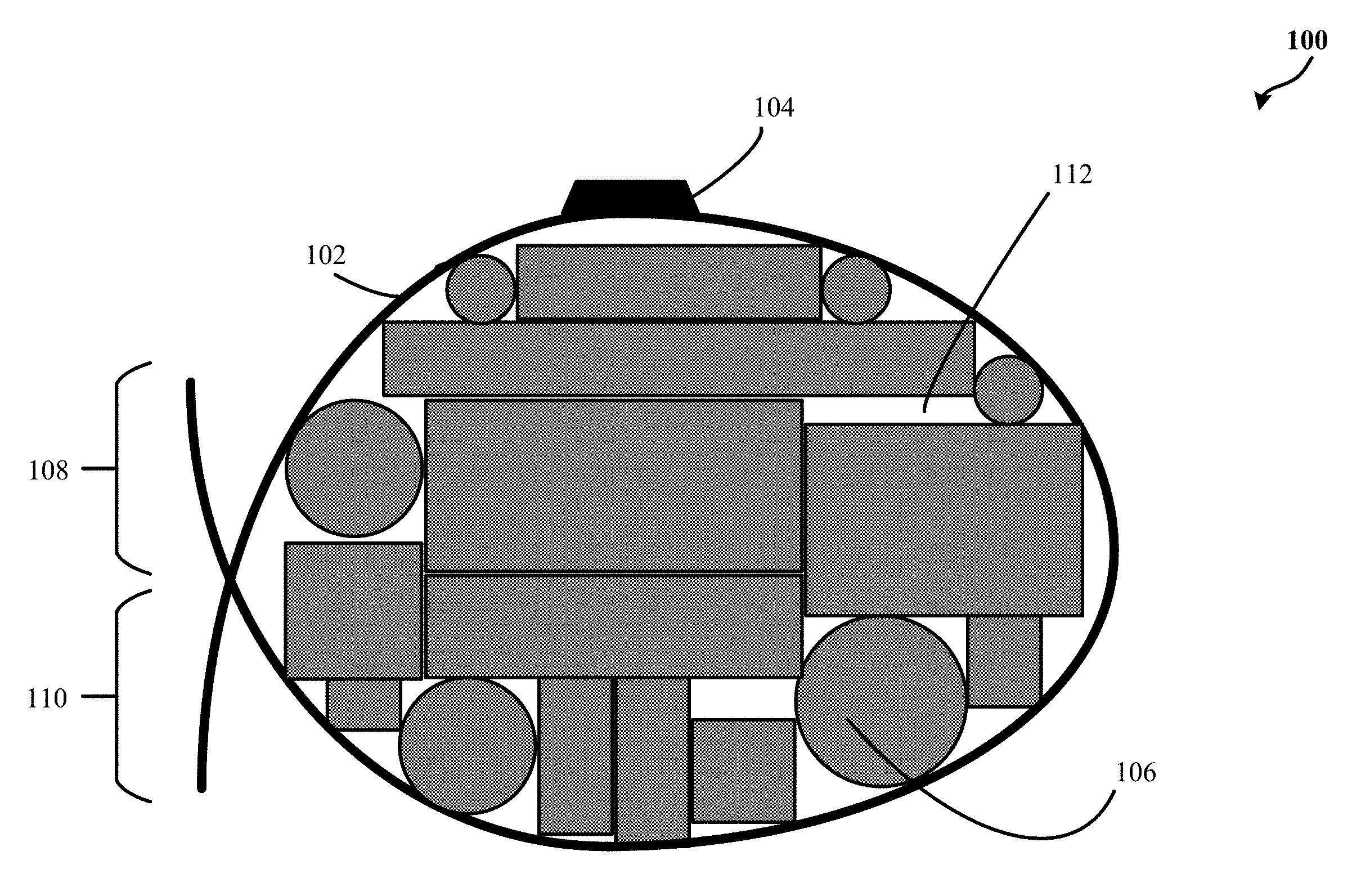
[0021] FIG. 1 is a simplified schematic illustration of an exemplary apparatus 100 for packing commercial product items for delivery in accordance with some embodiments. The apparatus 100 includes an elongated strip 102. By one approach, the elongated strip 102 may include a material that is at least flexible and bendable. For example, the elongated strip 102 may include a cardstock, a pliable plastic, a rubber, and/or other types of materials that are durable, pliable, and configured to secure and/or hold one or more commercial product items 106 in a generally fixed arrangement against each other. By one approach, the elongated strip 102 may be wrapped around the one or more commercial product items 106 to form a volume 112 to store the one or more commercial product items 106 during a delivery. For example, the one or more commercial product items 106 may settle in a generally fixed arrangement against each other where unused or unoccupied spaces in the volume 112 are substantially minimized by the settling of the commercial product items 106 as the elongated strip 102 is wrapped around a perimeter of the one or more commercial product items 106. In one configuration, the elongated strip 102 may include a first portion. In one example, the first portion may include a first end 108 of the elongated strip 102. In another example, the first portion may include a second end 110 of the elongated strip 102. In one implementation, as the first end 108 is drawn towards the second end 110, the elongated strip 102 may take a generally or substantially spherical and/or oval form that may be caused by the pressure exerted by the commercial products 106 being squeezed inside the volume 112. As such, each package formed by the cooperation of the elongated strip 102 and the commercial product items 106 may be customized (due to the package's shape being formed based, in part, on the commercial product items 106 and the pressure applied by the elongated strip 102 when wrapping the commercial product items 106) and minimal packaging materials may be used to, thereby, provide a more aerodynamic, weight efficient packaging method of packages destined to be delivered by a UAV. For example, the first end 108 may be drawn towards the second end 110 up until a predetermined pressure is reached. By one approach, the predetermined pressure may be based on one or more materials the elongated strip 102 is made out of. In some embodiments, the apparatus 100 may include at least one unmanned aerial vehicle (UAV) coupling device 104. For example, the UAV coupling device 104 may be formed in and/or secured along a portion of a length of the elongated strip 102, such as secured (e.g., using one or more types of adhesive material generally found in packaging and/or manufacturing products) to the first portion of the elongated strip 102. In one configuration, the UAV coupling device 104 may include a plate configured to couple the elongated strip 102 to a UAV (not shown) configured to deliver the package having the one or more commercial product items 106. For example, UAV coupling device 104 may be configured to have a thickness to maintain stability of the package formed by the elongated strip 102 wrapped around a perimeter of the commercial product items 106 during a delivery by a UAV. In an illustrative non-limiting example, the thickness may be about 100, 60, or even less than or within a threshold equal to 30 millimeters. The thickness may vary between different lengths and/or sizes of the elongated strip 102 and/or threshold weights of the collection of product items 106 that are to be cooperated into the package by the elongated strip 102. Additionally or alternatively, the thickness of the UAV coupling device 104 may typically depends on one or more intended methods utilized by one or more UAVs that are intended to couple with and transport the packages.
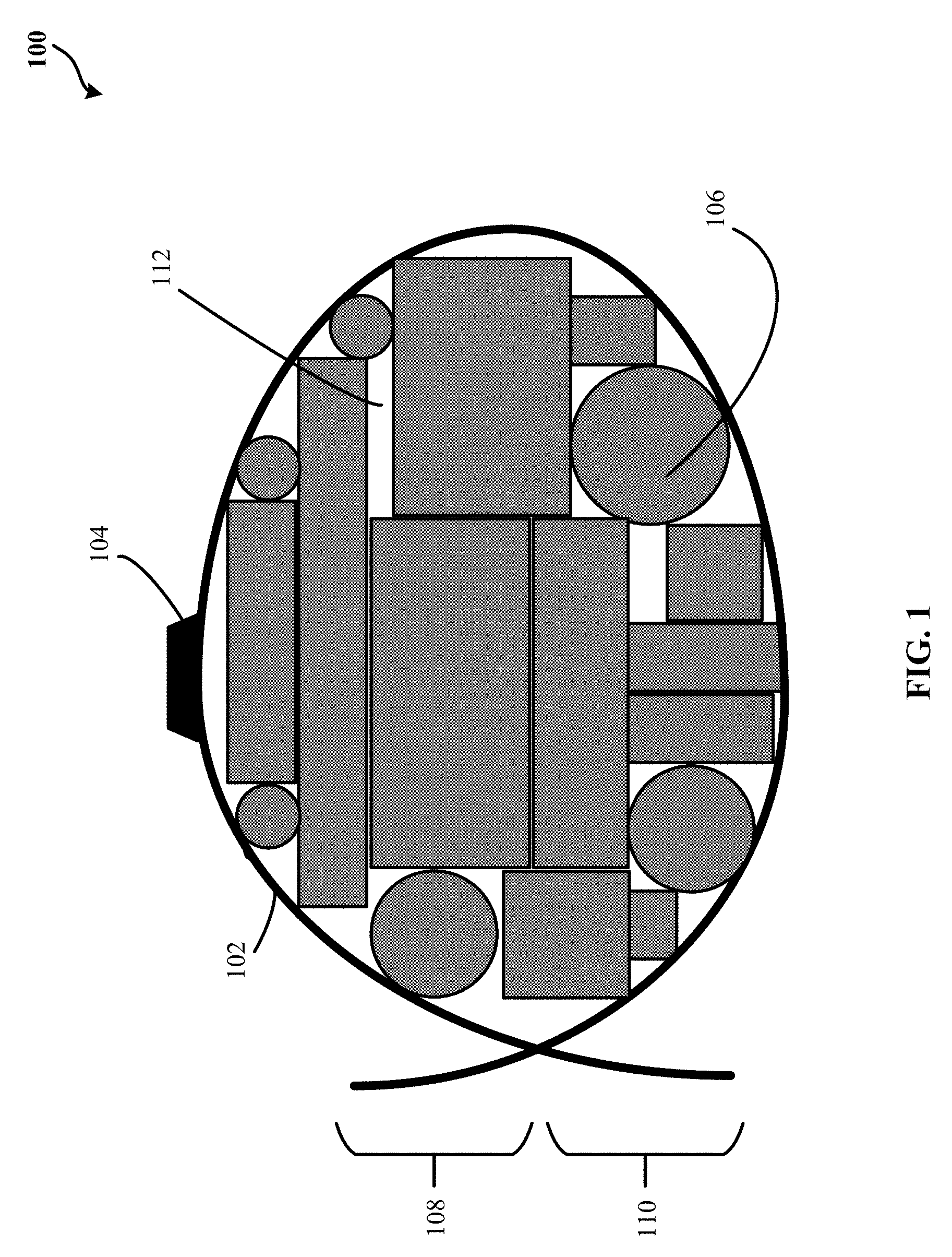
[0022] FIG. 2 is a simplified schematic illustration of an exemplary apparatus 200 for packing commercial product items for delivery in accordance with some embodiments. By one approach, the apparatus 200 includes the elongated strip 102 and the UAV coupling device 104 of FIG. 1. For example, FIGS. 1-2 illustrate the elongated strip 102 securing and/or holding the commercial product items 106 during a delivery by securing the first end 108 with the second end 110 of the elongated strip 102 to generally fix the arrangement of the commercial product items 106 inside the volume 112. In such an example, the elongated strip 102 may wrap around a perimeter of the one or more commercial product items 106 and hold the one or more commercial product items 106 in a generally fixed arrangement against each other and leaving portions of the one or more commercial product items 106 exposed where not covered by the elongated strip 102. In one example, the elongated strip 102 that is used to create a package may depend on a quantity and/or estimated total weight of the one or more commercial product items 106 to be wrapped around by the elongated strip 102. In such an example, a width and/or a length of the elongated strip 102 may be based, in part, on the quantity and/or the estimated total weight of the commercial product items 106. By another approach, when the commercial product items 106 are held in a generally fixed arrangement by the elongated strip 102, a wrapping material 202 is wrapped over the commercial product items 106 to cover at least exposed areas of the commercial product items 106 not covered by the elongated strip 102. For example, the wrapping material 202 may include cellophane wrapping materials, biaxially-oriented polypropylene (BOPP), cling wraps, among other types of wrapping materials. In one scenario, the wrapping material 202 is configured to secure the commercial product items 106 in a generally fixed arrangement formed by the elongated strip 102. By another approach, the wrapping material 202 may completely wrap the commercial product items 106 and the elongated strip 102. In some configuration, the UAV coupling device 104 may be wrapped by the wrapping material 202 when the wrapping material 202 completely wraps the commercial product items 106 and the elongated strip 102. In such a configuration, a package attachment system 302 of FIG. 3 of a UAV may pierce through the wrapping material 202 when attaching to the UAV coupling device 104. In another configuration, the wrapping material 202 may be substantially tightly wrapped around the commercial product items 106 to further secure and/or hold the commercial product items 106 in the generally fixed arrangement formed by the elongated strip 102. In some embodiments, the apparatus 100 of FIG. 1 and/or the apparatus 200 of FIG. 2 may be for a single use and, thus, may only be used one time in a delivery.
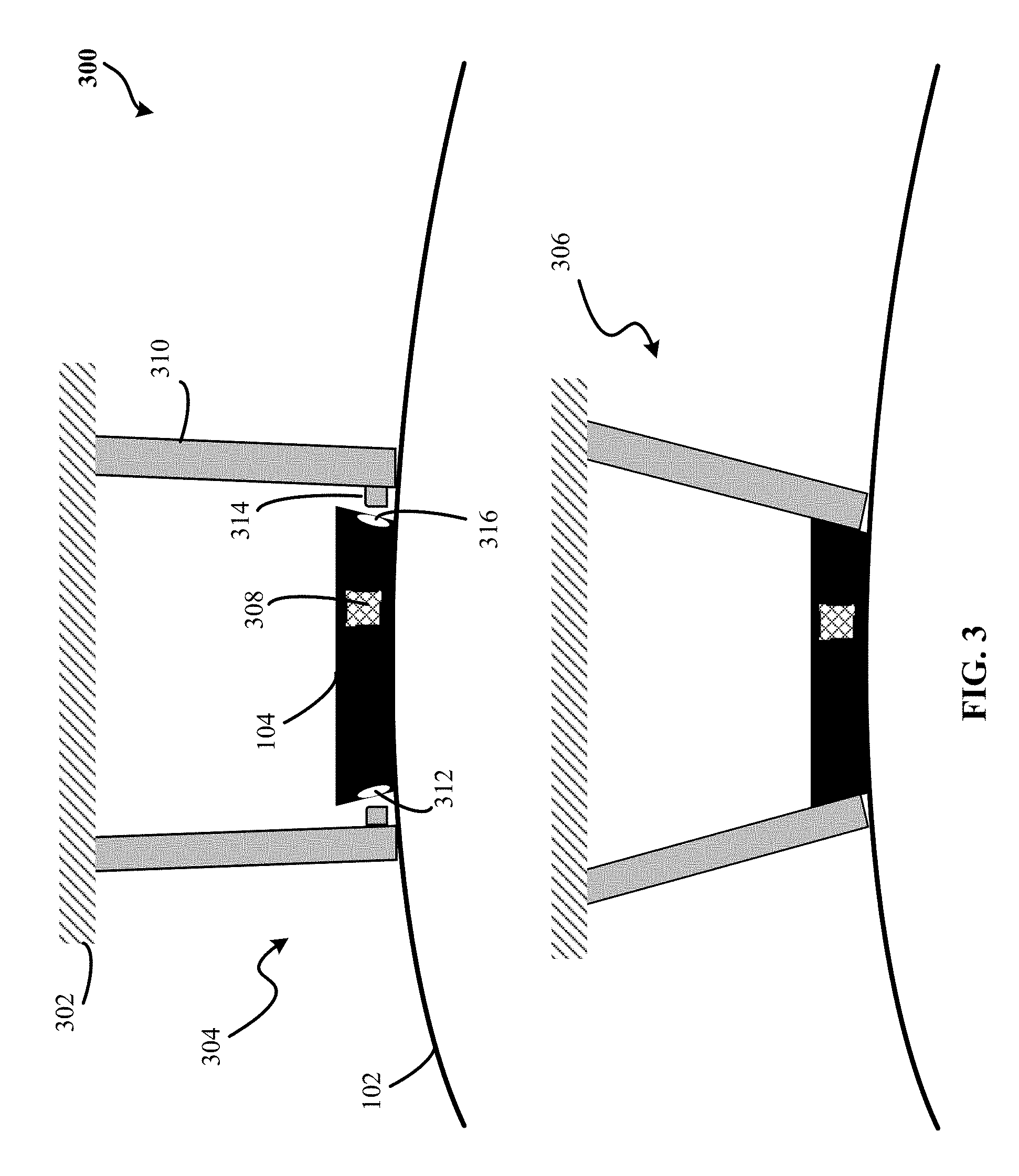
[0023] FIG. 3 is a schematic illustration of an exemplary UAV coupling device 104 in accordance with some embodiments. In one configuration, the UAV coupling device 104 may include a plate configured to couple the elongated strip 102 to a UAV. In such a configuration, the UAV coupling device 104 may be interchangeably referred to as a plate 104. By one approach, the plate 104 may include a first notch 312 and a second notch 316. In one implementation, the second notch 316 may be substantially opposite the first notch 312 and separated from the first notch by a distance. In some instances, the distance is the width of the plate, while in other instances one or more cavities are formed within the plate and further include the notches. By another approach, the plate 104 may include a plurality of notches including the first notch 312 and the second notch 316. By another approach, the plate 104 may include a plate identifier 308. For example, the plate identifier 308 may be particularly associated with the plate 104 and/or the commercial product items 106. Alternatively or in addition to, the plate identifier 308 may include an optical-based identification tag, a radio frequency identification (RFID) tag, among other types of identification tags associable with the plate 104. In one scenario, an RFID reader may read the RFID tag to track and/or confirm receipt of the one or more commercial product items 106. In one implementation, a control circuit 1002 shown on FIG. 10 may identify which one or more commercial product items 106 are carried by a UAV during a delivery based on the plate identifier 308. Alternatively or in addition to, the elongated strip 102 may include a strip identifier (not shown) similar to the plate identifier 308 to track and/or confirm receipt of the one or more commercial product items 106. As such, the strip identifier may include an optical-based identification tag, an RFID tag, among other types of identification tags associable with the strip identifier. In some embodiments, one or more claws 310 of the package attachment system 302 of a UAV may couple to the plate 104 when the plate 104 receives first handle(s) 314 of the claw(s) 310 as shown in a close configuration 306 of a UAV coupled to a package secured and/or held by the elongated strip 102 (for example, as depicted in the apparatus 100 of FIG. 1 and the apparatus 200 of FIG. 2), to deliver the one or more commercial product items 106. In another configuration, when the UAV delivers the package to a delivery destination, the first handle(s) 314 of the claw(s) 310 detach from the notches 312, 316 as shown in an open configuration 304 of the UAV coupled to the package.
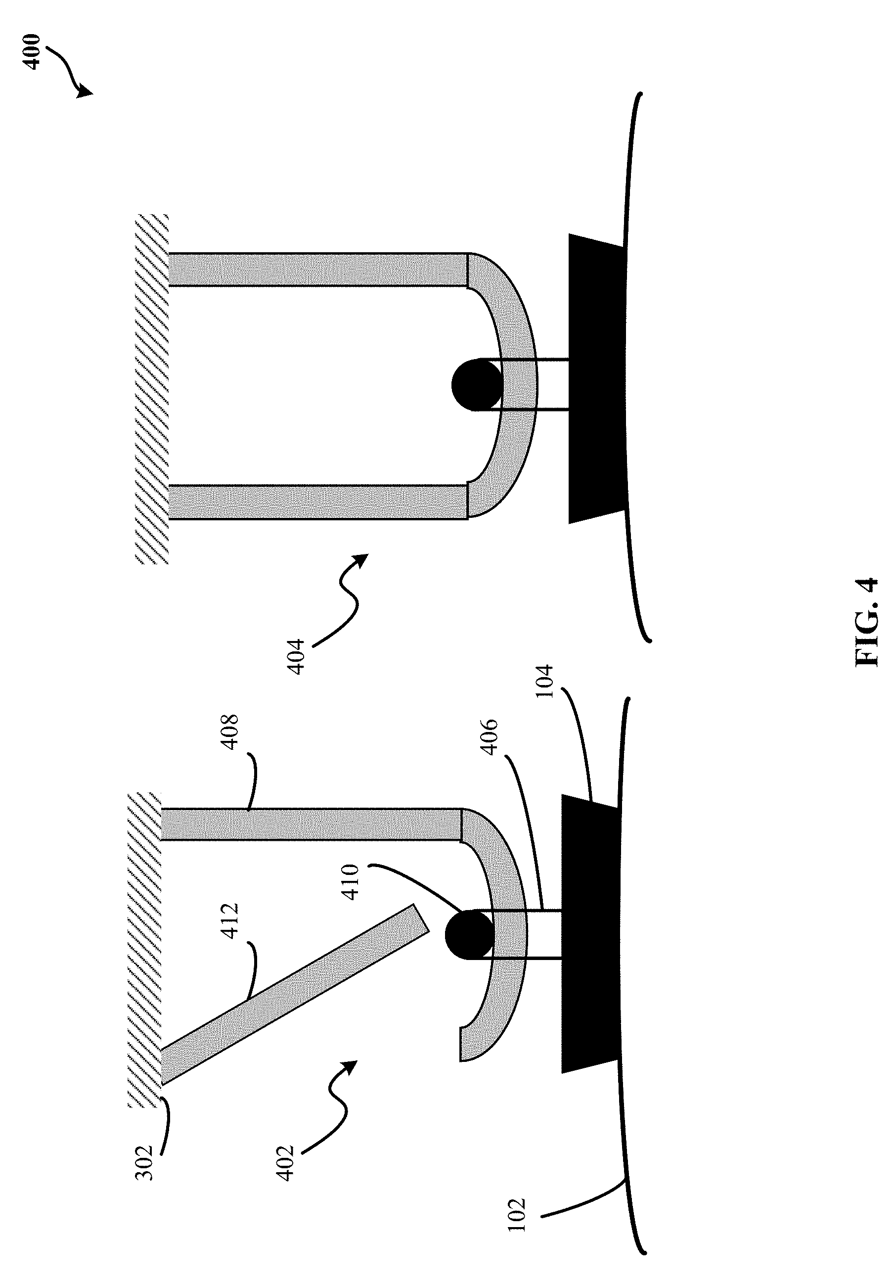
[0024] FIG. 4 is a schematic illustration of an exemplary UAV coupling device 104 in accordance with some embodiments. FIG. 4 illustrates a UAV coupling device 104 including a plate and a line cord 406 coupled to the plate. As such, the UAV coupling device 104 may be interchangeably referred to as a plate 104. By one approach, the line cord 406 is coupled to a first surface of the plate 104 that is opposite a second surface of the plate 104, where the second surface is secured to the first portion of the elongated strip 102. For example, the line cord 406 may hook over a second handle 410 of the package attachment system 302 of a UAV to carry the one or more commercial product items 106. In one implementation, the second handle 410 may include a circular ball, a hook, and/or any other type of shapes that receive the line cord 406 and secure the line cord 406 from detaching from the package attachment system 302. In some embodiments, the package attachment system 302 may include a J-hook claw 408 and/or a snap-latch 412. By one approach, when the J-hook claw 408 is in an open configuration 402, the line cord 406 may be hooked over the second handle 410 through unattached end of the J-hook claw 408 and over the second handle 410 so as to keep the line cord 406 from sliding passed the second handle 410 towards the unattached end of the J-hook claw 408. As such, to secure the line cord 406 to the J-hook claw 408, the snap-latch 412 is latched as shown in a close configuration 404 of the J-hook claw 408. Alternatively or in addition to, the line cord 406 may be hook over the second handle 410 so as to have the line cord 406 held and kept by the second handle 410 from becoming detached from the J-hook claw 408. In another example, the line cord 406 may be released from the J-hook claw 408 when the J-hook claw 408 swings out or away from the second handle 410 and the snap-latch 412 swings towards the J-hook claw 408, and thereby, enabling the line cord 406 to slip over the second handle 410 and off the J-hook claw 408. In some embodiments, the plate 104 may include one or more threaded holes 602 as shown in FIG. 6 to receive one or more screws of the package attachment system 302 of a UAV. By one approach, the one or more screws of the package attachment system 302 may be driven by a motor of the package attachment system 302. For example, the one or more threaded holes 602 may include threaded bushings, captive nuts, mold-in inserts, press fit inserts, pre-tapped holes, externally-threaded inserts, helical inserts, and/or among other types of threaded inserts. FIGS. 3-4 and descriptions illustrated above are illustrative non-limiting examples of the plate 104. As such, those skilled in the art will recognize that a wide variety of other modifications, alterations, and combinations can also be made with respect to the above described embodiments of the plate 104, particularly those plate 104 coupled to an elongated strip 102 to carry a package including the one or more commercial product items 106.
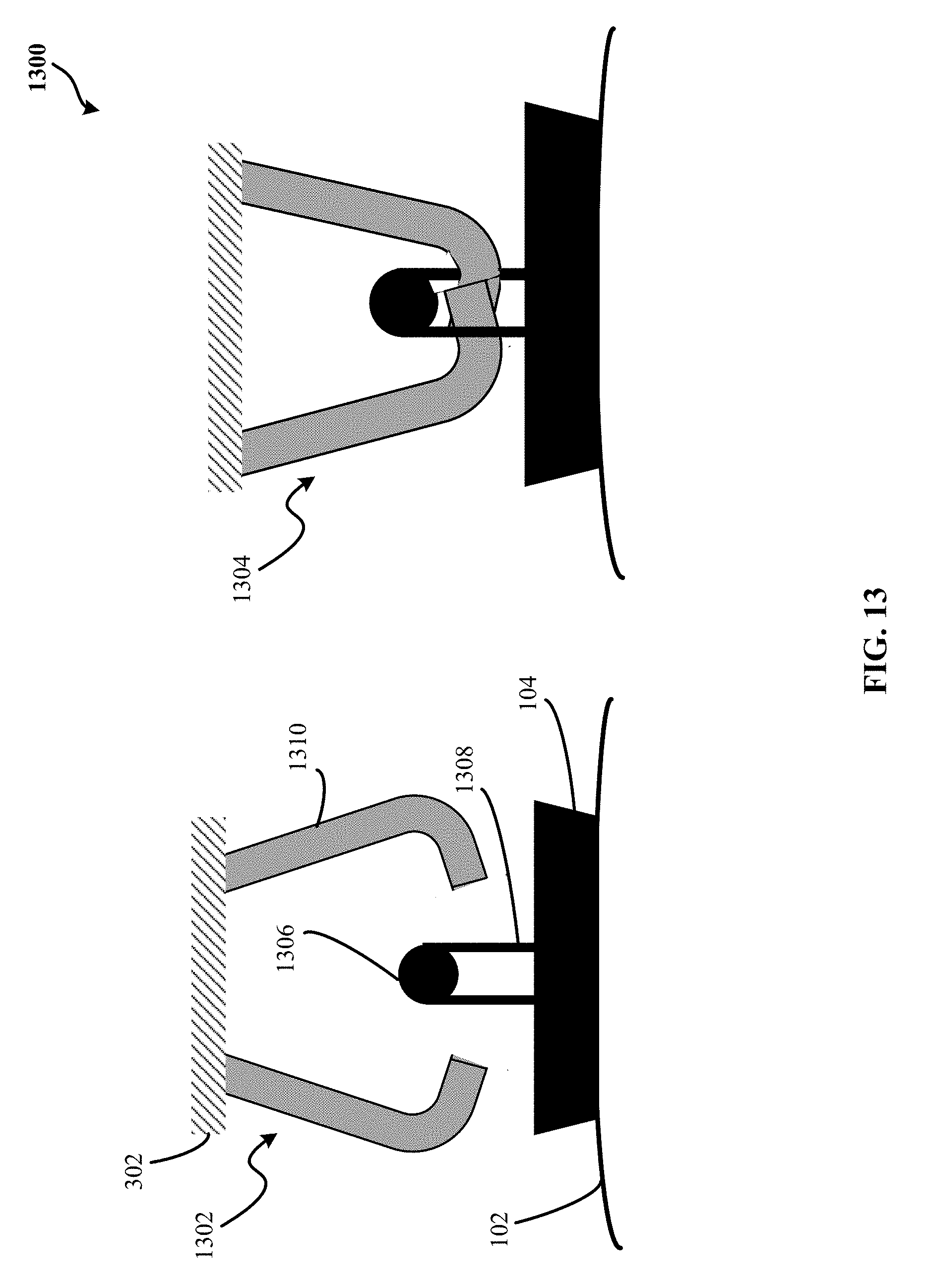
[0025] In another illustrative non-limiting example, the UAV coupling device 104 may be illustrated as shown in FIG. 13. FIG. 13 is a schematic illustration of an exemplary UAV coupling device 104 in accordance with some embodiments. FIG. 13 illustrates a UAV coupling device 104 including a plate and a third handle formed by a shaft 1306 and shaft-support 1308. Similar to FIG. 4, the UAV coupling device 104 may be interchangeably referred to as a plate 104. In one configuration, the shaft-support 1308 is a fix structure that renders the third handle in a fixed upright position. In another configuration, the shaft-support 1308 is collapsible, and thus, enabling the shaft 1306 to fall down substantially on top of the plate 104 when a plurality of claws 1310 coupled to the package attachment system 302 of a UAV release the third handle by swinging out or away from the third handle as illustrated in a release position 1302 of the UAV. By one approach, to carry a package formed by the elongated strip 102 wrapped around a perimeter of the commercial product items 106 as shown in FIGS. 1 and 2, for example, the plurality of claws 1310 interlace and/or slide under the third handle as illustrated in a lock position 1304 of the UAV.
[0026] Referring back to FIG. 5, FIG. 5 is a schematic illustration of an exemplary elongated strip 102 in accordance with some embodiments. By one approach, the elongated strip 102 may include the plate 104 in the first portion of the elongated strip 102 and a securing mechanism at a second portion of the elongated strip 102. In one configuration, the securing mechanism is configured to secure and/or hold the elongated strip 102 around the one or more commercial product items 106 in the generally fixed arrangement. For example, the securing mechanism may include an adhesive portion, one or more staple fasteners, tape, among other ways to secure the first end 108 to the second end 110. In some scenario, the adhesive portion may include a first adhesive portion 502 and a second adhesive portion 504. In one implementation, the elongated strip 102 may include the first end 108 of the elongated strip 102 including the adhesive portion. In one configuration, the second end 110 of the elongated strip 102 may include an opening 506. In some scenario, the first portion of the elongated strip 102 may include the opening 506. For example, in holding the one or more commercial product items 106 in a generally fixed arrangement, the adhesive portion of the first end 108 may be substantially inserted through the opening 506 and coupled and/or secured to the second end 110 as shown in FIG. 7. FIG. 7 is a schematic illustration of an exemplary securing mechanism 700 in accordance with some embodiments. For example, to secure the first end 108 to a back side of the second end 110, the first adhesive portion 502 and/or the second adhesive portion 504 may be peeled off to expose an adhesive material (e.g., dextrin, starch-based adhesive, among other ways to bond materials together) to bond and/or affix the first end 108 to the back side of the second end 110. In another example, the adhesive portion of the first end 108 of the elongated strip 102 may be completely inserted through the opening 506 to couple and/or secure the second end 110 to the first end 108 of the elongated strip 102. For example, the first adhesive portion 502 and/or the second adhesive portion 504 may be wet to activate an adhesive material to bond the first end 108 to the back side of the second end 110.
[0027] FIG. 6 is a schematic illustration of an exemplary elongated strip 102 in accordance with some embodiments. Alternatively or in addition to, the plate 104 may include the one or more threaded holes 602. As such, the elongated strip 102 may include the first adhesive portion 502, the second adhesive portion 504, and the opening 506. By one approach, the plate 104 in FIGS. 1-6 may be interchangeable with another plate 104 of a different type. For example, the plate 104 shown in FIG. 5 may be changed with the plate 104 of FIG. 6 depending on a type of the package attachment system 302 coupled to a UAV assigned to deliver the one or more commercial product items 106.
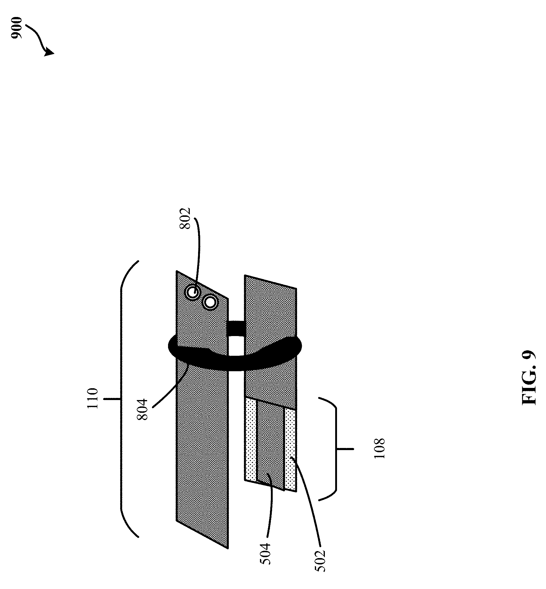
[0028] FIG. 8 is a schematic illustration of an exemplary elongated strip 102 in accordance with some embodiments. By one approach, the elongated strip 102 may include one or more grippers 802, the first adhesive portion 502, the second adhesive portion 504, and/or a belt loop 804. In one configuration, the first end 108 of the elongated strip 102 may include an adhesive portion (e.g., the first adhesive portion 502 and/or the second adhesive portion 504). Alternatively or in addition to, the second end 110 of the elongated strip 102 may include the one or more grippers 802, and/or the belt loop 804. For example, the belt loop 804 of the elongated strip 102 may guide the second end 110 over the adhesive portion of the first end 108 of the elongated strip to further secure the elongated strip 102 around the perimeter of the one or more commercial product items 106 as shown in FIG. 9. FIG. 9 is a schematic illustration of an exemplary securing mechanism 900 in accordance with some embodiments. In an illustrative non-limiting example, the one or more grippers 802 are positioned adjacent to an edge of the second end 110 of the elongated strip 102. By one approach, the one or more grippers 802 may detachably couple to a robotic arm. In such an approach, the robotic arm may guide the second end 110 over the adhesive portion (e.g., the first adhesive portion 502 and/or the second adhesive portion 504) of the first end 108 of the elongated strip 102. In one example, the adhesive portion is fed through the belt loop 804 prior to bonding or affixing the adhesive portion to the back side of the second end 110 of the elongated strip 102. By one approach, FIGS. 1 and 2 may implement the securing mechanism 900. In such an approach, the securing mechanism 900 may include the one or more grippers 802. In one example, the one or more grippers 802 may include grommets, eyelets, and/or other types of fasteners that enable a robotic arm and/or a mechanical device to couple to the second end 110 of the elongated strip 102 and guide the second end 110 over the first end 108. Alternatively or in addition to, the belt loop 804 may be tightened to further secure and/or hold the commercial product items 106 in a generally fixed arrangement against each other. For example, the belt loop 804 may include a rubber material and a tie-down, among other materials used to guide and/or tighten and secure materials together.
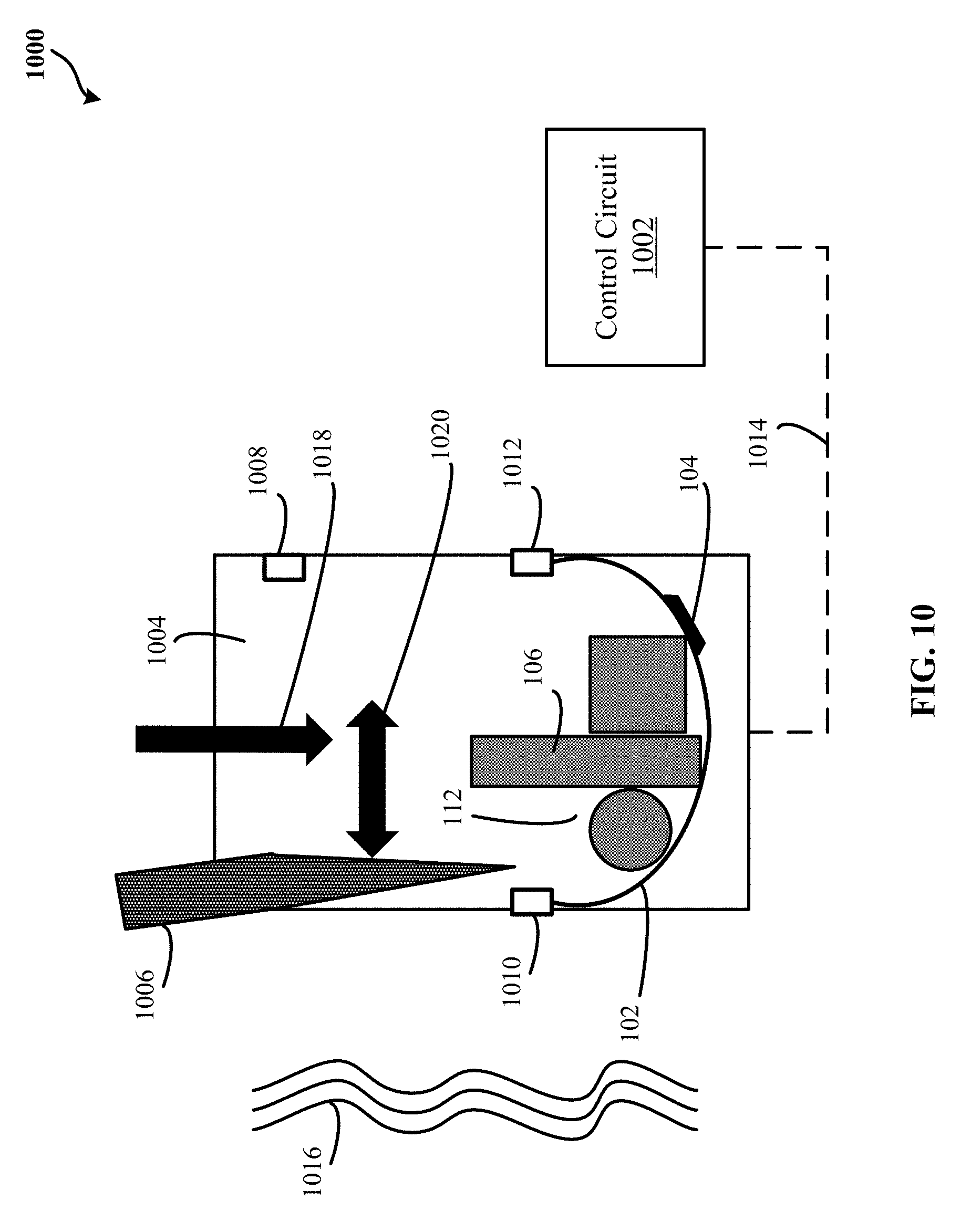
[0029] FIG. 10 is a schematic illustration of an exemplary system 1000 for packing items for delivery in accordance with some embodiments. By one approach, the system 1000 includes the elongated strip 102 as depicted in one or more of FIGS. 1-9. In one configuration, the system 1000 may include a conveyor 1004. In one implementation, the conveyor 1004 may move one or more commercial product items 106 towards an opening of the elongate strip 102 as depicted by a first arrow 1018. By one approach, the system 1000 may include a holding structure. In one configuration, the holding structure may include a first arm end 1010 and a second arm end 1012. Alternatively or in addition to, the holding structure may hold the elongated strip 102 in a U-shape forming the volume 112. For example, the one or more commercial product items 106 may be received and retained in the volume 112 as the one or more commercial product items 106 travel on the conveyor 1004 as depicted by the first arrow 1018. In another example, vibrating motion 1016 of the conveyor 1004 may cause the one or more commercial product items 106 to be positioned in a generally fixed arrangement against each other. By another approach, the system 1000 may include one or more sensors 1008 may read identification tags of the one or more commercial product items 106 as the commercial product items 106 travels down the conveyor 1004 towards the volume 112 as depicted by the first arrow 1018. By another approach, the system 1000 may include the control circuit 1002. In one configuration, the control circuit 1002 may determine a quantity of the commercial product items 106 received in the volume 112 based on the identification tags read by the one or more sensors 1008. In one example, a memory device (not shown) may be initiated by the control circuit 1002 to store the identification tags as the identification tags are read by the sensor(s) 1008. By one approach, based on the stored identification tags and the plate identifier 308 associated with the elongated strip 102, the control circuit 1002 may determine which commercial product items 106 are in a package destined for delivery to a delivery destination by a UAV, where the package includes the elongated strip 102 securing and/or holding the commercial products 106 in a streamlined packing arrangement and/or in a generally fixed arrangement against each other. In one implementation, the control circuit 1002 may determine whether the quantity is equal to a predetermined threshold associated with the elongated strip 102. For example, the control circuit 1002 may determine that the elongated strip 102 is associated with a particular predetermined threshold of quantity that the elongated strip 102 may secure and/or hold inside the volume 112 to effectuate a streamlined packing arrangement and/or a generally fixed arrangement during a delivery. As such, when the quantity surpasses the particular predetermined threshold, the first end 108 and the second end 110 of the elongated strip 102 may inadvertently detach from one another and cause the commercial product items 106 to spill out of the volume 112. In one example, one or more predetermined thresholds and/or corresponding elongated strips 102 may be stored in a memory associated with the control circuit 1002. In another implementation, the control circuit 1002 may, in response to the quantity being equal to the predetermined threshold, initiate operation of the holding structure to secure the one or more commercial product items 106 in the volume 112 formed by the elongated strip 102 through operation of the first arm end 1010 and the second arm end 1012 by the control circuit 1002. In one configuration, the control circuit 1002 may provide a signal via a communication path 1014 to the conveyor 1004 to stop operation of the conveyor 1004 so that the first end 108 may be bonded and/or affixed to the second end 110 by the operation of the control circuit 1002 of the first arm end 1010 and/or the second arm end 1012. In one scenario, the communication path 1014 may include wireless and/or wired communication networks (e.g., Internet, WiFi, Ethernet, among other types of communications networks). In one implementation, when the first end 108 is bonded and/or affixed to the second end 110, the UAV coupling device 104 may be coupled to the package attachment system 302 of a UAV assigned to deliver the commercial product items 106 secured and/or held inside the volume 112. In some embodiments, the system 1000 may include a rod 1006. By one approach, the rod 1006 may be operatively coupled to the control circuit 1002 via the communication path 1014. In one configuration, the rod 1006 may nudge the one or more commercial product items 106 in the volume 112 as the first arm end 1010 and the second arm end 1012 operate to secure the one or more commercial product items 106 in the volume 112 via the securing mechanism of the elongated strip 102. For example, the securing mechanism may correspond to the securing mechanisms shown in FIGS. 5-9. By one approach, nudging the commercial product items 106 may further aid in positioning the commercial product items 106 inside the volume 112 in a generally fixed arrangement against each other.
[0030] FIG. 11 shows a flow diagram of an exemplary method 1100 of packing items for delivery in accordance with some embodiments. By one approach, the method 1100 may be implemented in the system 1000 of FIG. 10. By another approach, the system 1000 of FIG. 10 may implement the method 1100 using one or more components depicted in FIGS. 1-9. The method 1100 includes, at step 1102, determining a quantity of one or more commercial product items received in a volume based on identification tags corresponding to the commercial product items are read by one or more sensors associated with a conveyor system (e.g., the conveyor 1004). In one example, the volume may be formed when an elongated strip (e.g., the elongated strip 102) is bended to a U-shape. In one implementation, the method 1100 may include, at step 1104, determining whether the quantity is equal to a predetermined threshold associated with the elongated strip. In another implementation, the method 1100 may include, at step 1106, in response to the quantity being equal to the predetermined threshold, initiating operation of a holding structure to secure the one or more commercial product items in the volume formed by the elongated strip through operation of a first arm end and a second arm end of the holding structure. In one configuration, the holding structure may be operatively coupled to the conveyor system.
[0031] Further, the circuits, circuitry, systems, devices, processes, methods, techniques, functionality, services, servers, sources and the like described herein may be utilized, implemented and/or run on many different types of devices and/or systems. FIG. 12 illustrates an exemplary system 1200 that may be used for implementing any of the components, circuits, circuitry, systems, functionality, apparatuses, processes, or devices of the system 1000 of FIG. 10, the method 1100 of FIG. 11, and/or other above or below mentioned systems or devices, or parts of such circuits, circuitry, functionality, systems, apparatuses, processes, or devices. For example, the system 1200 may be used to implement some or all of the system 1000 for packing items for delivery, the control circuit 1002, and/or other such components, circuitry, functionality and/or devices. However, the use of the system 1200 or any portion thereof is certainly not required.
[0032] By way of example, the system 1200 may comprise a processor module (or a control circuit) 1212, memory 1214, and one or more communication links, paths, buses or the like 1218. Some embodiments may include one or more user interfaces 1216, and/or one or more internal and/or external power sources or supplies 1240. The control circuit 1212 can be implemented through one or more processors, microprocessors, central processing unit, logic, local digital storage, firmware, software, and/or other control hardware and/or software, and may be used to execute or assist in executing the steps of the processes, methods, functionality and techniques described herein, and control various communications, decisions, programs, content, listings, services, interfaces, logging, reporting, etc. Further, in some embodiments, the control circuit 1212 can be part of control circuitry and/or a control system 1210, which may be implemented through one or more processors with access to one or more memory 1214 that can store instructions, code and the like that is implemented by the control circuit and/or processors to implement intended functionality. In some applications, the control circuit and/or memory may be distributed over a communications network (e.g., LAN, WAN, Internet) providing distributed and/or redundant processing and functionality. Again, the system 1200 may be used to implement one or more of the above or below, or parts of, components, circuits, systems, processes and the like. For example, the system 1200 may implement the system 1000 for packing one or more items for delivery with the control circuit 1002 being the control circuit 1212.
[0033] The user interface 1216 can allow a user to interact with the system 1200 and receive information through the system. In some instances, the user interface 1216 includes a display 1222 and/or one or more user inputs 1224, such as buttons, touch screen, track ball, keyboard, mouse, etc., which can be part of or wired or wirelessly coupled with the system 1200. Typically, the system 1200 further includes one or more communication interfaces, ports, transceivers 1220 and the like allowing the system 1200 to communicate over a communication bus, a distributed computer and/or communication network (e.g., a local area network (LAN), the Internet, wide area network (WAN), etc.), communication link 1218, other networks or communication channels with other devices and/or other such communications or combination of two or more of such communication methods. Further the transceiver 1220 can be configured for wired, wireless, optical, fiber optical cable, satellite, or other such communication configurations or combinations of two or more of such communications. Some embodiments include one or more input/output (I/O) interface 1234 that allow one or more devices to couple with the system 1200. The I/O interface can be substantially any relevant port or combinations of ports, such as but not limited to USB, Ethernet, or other such ports. The I/O interface 1234 can be configured to allow wired and/or wireless communication coupling to external components. For example, the I/O interface can provide wired communication and/or wireless communication (e.g., Wi-Fi, Bluetooth, cellular, RF, and/or other such wireless communication), and in some instances may include any known wired and/or wireless interfacing device, circuit and/or connecting device, such as but not limited to one or more transmitters, receivers, transceivers, or combination of two or more of such devices.
[0034] In some embodiments, the system may include one or more sensors 1226 to provide information to the system and/or sensor information that is communicated to another component, such as the central control system, a portable retail container, a vehicle associated with the portable retail container, etc. The sensors can include substantially any relevant sensor, such as temperature sensors, distance measurement sensors (e.g., optical units, sound/ultrasound units, etc.), optical based scanning sensors to sense and read optical patterns (e.g., bar codes), radio frequency identification (RFID) tag reader sensors capable of reading RFID tags in proximity to the sensor, and other such sensors. The foregoing examples are intended to be illustrative and are not intended to convey an exhaustive listing of all possible sensors. Instead, it will be understood that these teachings will accommodate sensing any of a wide variety of circumstances in a given application setting.
[0035] The system 1200 comprises an example of a control and/or processor-based system with the control circuit 1212. Again, the control circuit 1212 can be implemented through one or more processors, controllers, central processing units, logic, software and the like. Further, in some implementations the control circuit 1212 may provide multiprocessor functionality.
[0036] The memory 1214, which can be accessed by the control circuit 1212, typically includes one or more processor readable and/or computer readable media accessed by at least the control circuit 1212, and can include volatile and/or nonvolatile media, such as RAM, ROM, EEPROM, flash memory and/or other memory technology. Further, the memory 1214 is shown as internal to the control system 1210; however, the memory 1214 can be internal, external or a combination of internal and external memory. Similarly, some or all of the memory 1214 can be internal, external or a combination of internal and external memory of the control circuit 1212. The external memory can be substantially any relevant memory such as, but not limited to, solid-state storage devices or drives, hard drive, one or more of universal serial bus (USB) stick or drive, flash memory secure digital (SD) card, other memory cards, and other such memory or combinations of two or more of such memory, and some or all of the memory may be distributed at multiple locations over the computer network. The memory 1214 can store code, software, executables, scripts, data, content, lists, programming, programs, log or history data, user information, customer information, product information, and the like. While FIG. 12 illustrates the various components being coupled together via a bus, it is understood that the various components may actually be coupled to the control circuit and/or one or more other components directly.
[0037] Those skilled in the art will recognize that a wide variety of other modifications, alterations, and combinations can also be made with respect to the above described embodiments without departing from the scope of the invention, and that such modifications, alterations, and combinations are to be viewed as being within the ambit of the inventive concept.
* * * * *
D00000
D00001
D00002
D00003
D00004
D00005
D00006
D00007
D00008
D00009
D00010
D00011
D00012

D00013
XML
uspto.report is an independent third-party trademark research tool that is not affiliated, endorsed, or sponsored by the United States Patent and Trademark Office (USPTO) or any other governmental organization. The information provided by uspto.report is based on publicly available data at the time of writing and is intended for informational purposes only.
While we strive to provide accurate and up-to-date information, we do not guarantee the accuracy, completeness, reliability, or suitability of the information displayed on this site. The use of this site is at your own risk. Any reliance you place on such information is therefore strictly at your own risk.
All official trademark data, including owner information, should be verified by visiting the official USPTO website at www.uspto.gov. This site is not intended to replace professional legal advice and should not be used as a substitute for consulting with a legal professional who is knowledgeable about trademark law.