Bicycle Operation Device
KOMATSU; Atsushi ; et al.
U.S. patent application number 16/445317 was filed with the patent office on 2019-10-10 for bicycle operation device. The applicant listed for this patent is Shimano Inc.. Invention is credited to Atsushi KOMATSU, Takehiko NAKAJIMA, Takafumi NISHINO.
| Application Number | 20190308687 16/445317 |
| Document ID | / |
| Family ID | 61564326 |
| Filed Date | 2019-10-10 |


| United States Patent Application | 20190308687 |
| Kind Code | A1 |
| KOMATSU; Atsushi ; et al. | October 10, 2019 |
BICYCLE OPERATION DEVICE
Abstract
A bicycle operation device includes a clamp, an operation unit and a wireless communicator. The clamp is attachable to a handlebar of a bicycle. The operation unit includes a housing having an upper housing portion and a lower housing portion. The upper housing portion is located above the lower housing portion in a state in which the bicycle operation device is attached to the handlebar. The wireless communicator is configured to communicate with a bicycle component. The wireless communicator is provided on the upper housing portion.
| Inventors: | KOMATSU; Atsushi; (Osaka, JP) ; NAKAJIMA; Takehiko; (Osaka, JP) ; NISHINO; Takafumi; (Osaka, JP) | ||||||||||
| Applicant: |
|
||||||||||
|---|---|---|---|---|---|---|---|---|---|---|---|
| Family ID: | 61564326 | ||||||||||
| Appl. No.: | 16/445317 | ||||||||||
| Filed: | June 19, 2019 |
Related U.S. Patent Documents
| Application Number | Filing Date | Patent Number | ||
|---|---|---|---|---|
| 15686957 | Aug 25, 2017 | 10370056 | ||
| 16445317 | ||||
| Current U.S. Class: | 1/1 |
| Current CPC Class: | B62K 23/06 20130101; B60T 7/10 20130101; G05G 11/00 20130101; B62K 21/12 20130101; H04W 76/10 20180201; B62M 25/08 20130101 |
| International Class: | B62K 23/06 20060101 B62K023/06; B62M 25/08 20060101 B62M025/08; B60T 7/10 20060101 B60T007/10; H04W 76/10 20060101 H04W076/10; B62K 21/12 20060101 B62K021/12 |
Foreign Application Data
| Date | Code | Application Number |
|---|---|---|
| Sep 29, 2016 | JP | 2016-191957 |
Claims
1. A bicycle operation device comprising: a clamp that is attachable to a handlebar of a bicycle; an operation unit including a housing having an upper housing portion and a lower housing portion, the upper housing portion being located above the lower housing portion in a state in which the bicycle operation device is attached to the handlebar; and a wireless communicator configured to communicate with a bicycle component, the wireless communicator being provided on the upper housing portion.
2. The bicycle operation device according to claim 1, wherein the clamp is connected to the housing.
3. The bicycle operation device according to claim 1, wherein the housing includes a front housing portion and a rear housing portion, the front housing portion being located forward of the rear housing portion in a state in which the bicycle operation device is attached to the handlebar; and the wireless communicator is provided on at least one of the front housing portion and the rear housing portion.
4. The bicycle operation device according to claim 1, further comprising a bolt, the clamp having an insertion hole for receiving the bolt such that the operation unit is attachable to the clamp by the bolt.
5. The bicycle operation device according to claim 4, wherein the operation unit includes a projection that is fixed to the housing, the projection having a fastening hole for fastening the operation unit to the bolt.
6. The bicycle operation device according to claim 5, wherein the wireless communicator is disposed adjacent to the projection.
7. The bicycle operation device according to claim 1, wherein the operation unit further includes an electric switch configured to transmit a signal to the wireless communicator.
8. The bicycle operation device according to claim 1, further comprising the clamp including a first end and a second end, the first end includes a first insertion hole that receives a bolt, the second end including a second insertion hole that receives the bolt, and the operation unit being attached to the clamp by the bolt.
9. The bicycle operation device according to claim 8, wherein the wireless communicator is disposed adjacent to a fastening hole provided to the operation unit such that the bolt is coupled to the fastening hole.
10. The bicycle operation device according to claim 1, wherein the upper housing portion and the lower housing portion are separately formed and joined to form the housing.
11. The bicycle operation device according to claim 1, wherein the clamp is separate from a brake clamp that attaches a brake operation unit of the bicycle to the handlebar.
12. The bicycle operation device according to claim 7, wherein the electric switch includes a first switch and a second switch.
13. The bicycle operation device according to claim 7, wherein the electric switch includes a first switch, a second switch and a third switch.
14. The bicycle operation device according to claim 7, wherein the electric switch includes only a first switch.
15. The bicycle operation device according to claim 12, wherein the operation unit further includes a first operation member that operates the first switch and a second operation member that operates the second switch.
16. The bicycle operation device according to claim 15, wherein the first operation member includes a first lever that is pivotal about a first axis, and the second operation member includes a second lever that is pivotal about a second axis.
17. The bicycle operation device according to claim 1, wherein the housing includes a resin material.
Description
CROSS-REFERENCE TO RELATED APPLICATIONS
[0001] This application is a continuation application of U.S. application Ser. No. 15/686,957, filed Aug. 25, 2017, which claims priority to Japanese Patent Application No. 2016-191957, filed on Sep. 29, 2016. The entire disclosures of U.S. application Ser. No. 15/686,957 and Japanese Patent Application No. 2016-191957 are hereby incorporated herein by reference.
BACKGROUND
Field of the Invention
[0002] The present invention generally relates to a bicycle operation device.
Background Information
[0003] A bicycle operation device is known in the art that includes a wireless communication unit for communicating with a bicycle component. One example of a bicycle operation device includes a clamp attached to a handlebar of a bicycle, an operation unit integrally coupled to the clamp, and a wireless communicator arranged in the operation unit. U.S. Pat. No. 8,909,424 discloses one example of a known bicycle operation device.
SUMMARY
[0004] It is preferred that the position of the operation unit relative to the handlebar be easy to adjust. One object of the present disclosure is to provide a bicycle operation device that allows for easy adjustment of the position of the operation unit relative to the handlebar.
[0005] In accordance with an aspect of the present disclosure, a bicycle operation device includes a clamp, an operation unit and a wireless communicator. The clamp is attachable to a handlebar of a bicycle. The operation unit includes a housing having an upper housing portion and a lower housing portion. The upper housing portion is located above the lower housing portion in a state in which the bicycle operation device is attached to the handlebar. The wireless communicator is configured to communicate with a bicycle component. The wireless communicator is provided on the upper housing portion.
[0006] Thus, the position of the operation unit relative to the handlebar is easy to adjust.
BRIEF DESCRIPTION OF THE DRAWINGS
[0007] Referring now to the attached drawings which form a part of this original disclosure.
[0008] FIG. 1 is a perspective view of a bicycle operation device in accordance with a first embodiment.
[0009] FIG. 2 is an exploded perspective view showing the bicycle operation device of FIG. 1.
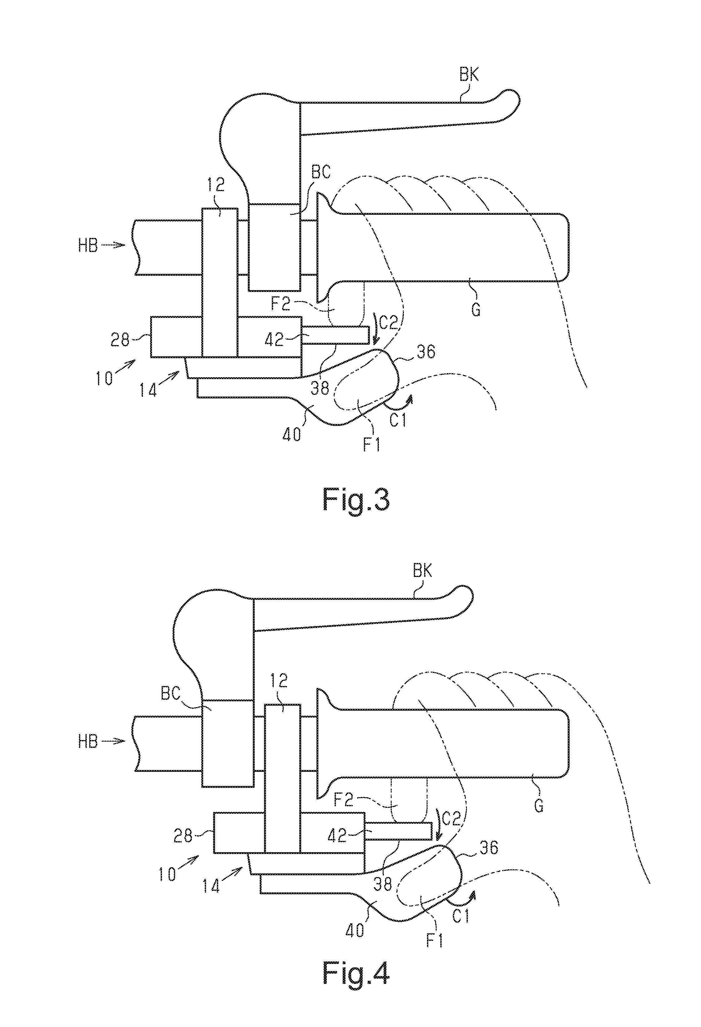
[0010] FIG. 3 is a plan view showing the bicycle operation device of FIG. 1 in a state attached to a handlebar.
[0011] FIG. 4 is a simplified top plan view showing the bicycle operation device of FIG. 1 in a state attached to a handlebar.
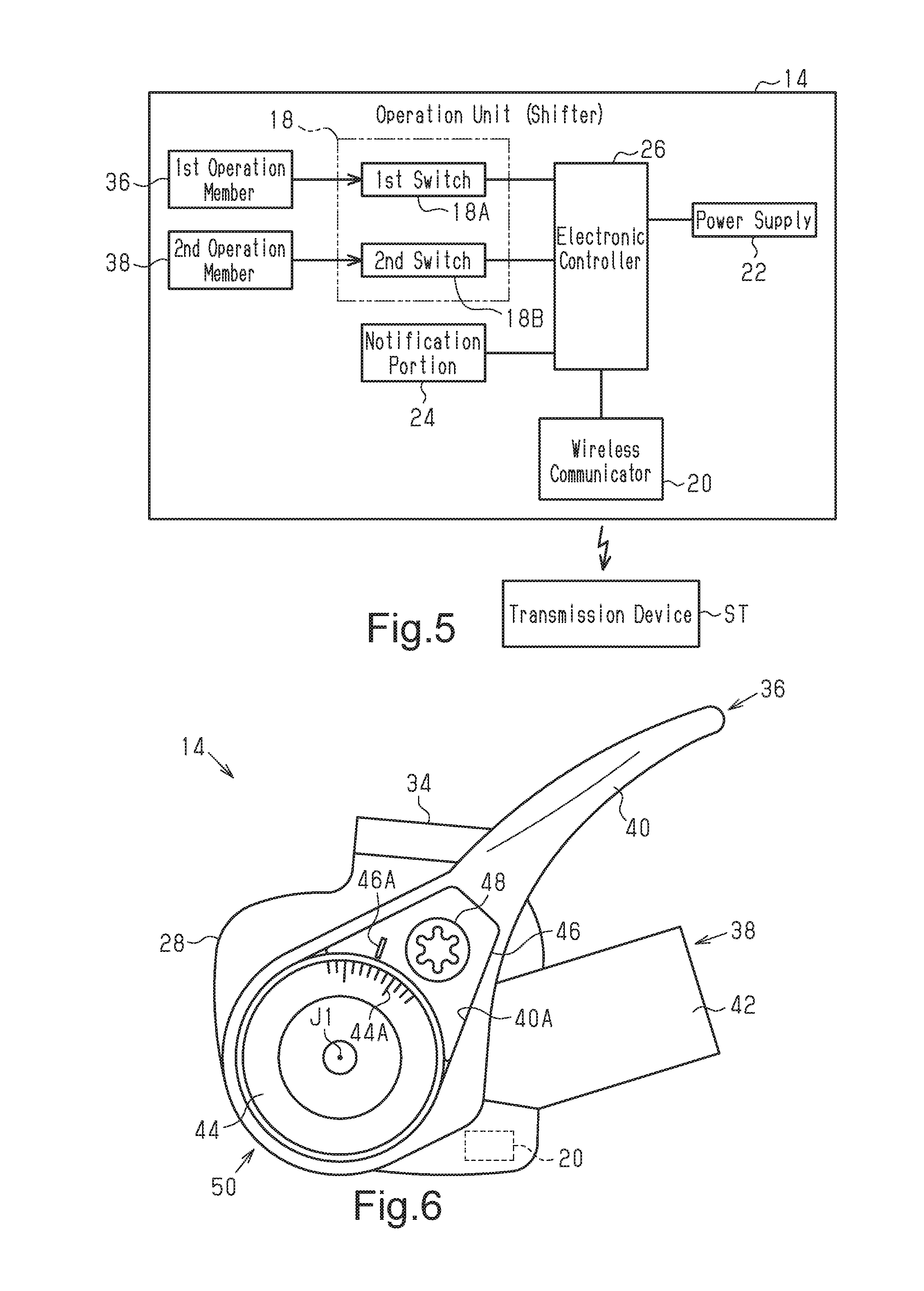
[0012] FIG. 5 is a block diagram showing an electrical configuration of an operation unit in the bicycle operation device of FIG. 1.
[0013] FIG. 6 is a front elevational view of the operation unit showing a second operation member.
[0014] FIG. 7 is a rear elevational view of the operation unit showing the second operation member.
[0015] FIG. 8 is a side elevational view of the operation unit showing the second operation member.
[0016] FIG. 9 is a front elevational view of the operation unit showing a first modification.
[0017] FIG. 10 is a rear elevational view of the operation unit showing a second modification.
[0018] FIG. 11 is a side elevational view of the operation unit showing a third modification.
[0019] FIG. 12 is a top plan view of the operation unit showing a fourth modification.
[0020] FIG. 13 is a top plan view of the operation unit of FIG. 12.
[0021] FIG. 14 is a block diagram showing the electrical configuration of a fifth modification.
[0022] FIG. 15 is a block diagram showing the electrical configuration of a sixth modification.
DETAILED DESCRIPTION OF EMBODIMENTS
[0023] Selected embodiments will now be explained with reference to the drawings. It will be apparent to those skilled in the bicycle field from this disclosure that the following descriptions of the embodiments are provided for illustration only and not for the purpose of limiting the invention as defined by the appended claims and their equivalents.
[0024] Referring to FIG. 1, a bicycle operation device 10 is attached to a handlebar HB of, for example, a mountain bike. The bicycle operation device 10 includes a clamp 12 and an operation unit 14. The clamp 12 is attachable to the handlebar HB of a bicycle. The operation unit 14 is attachable to the clamp 12. In further detail, the operation unit 14 is attachable to the clamp 12 in a manner allowing for removal of the operation unit 14 from the clamp 12 and adjustment of the position of the operation unit 14 relative to the clamp 12. One example of the operation unit 14 is a shifter that operates a transmission device ST. The transmission device ST includes at least one of a front transmission device and a rear transmission device.
[0025] As shown in FIG. 2, the bicycle operation device 10 further includes a coupling member 16. The clamp 12 is generally C-shaped in a side elevational view. The clamp 12 includes a first end 12A and a second end 12B. The first end 12A and the second end 12B are opposed to each other. The first end 12A includes a first insertion hole 12C into which the coupling member 16 is insertable. The second end 12B includes a second insertion hole 12D into which the coupling member 16 is insertable. In other words, the first and second insertion holes 12C and 12D each receives the coupling member 16. The coupling member 16 is configured to adjust the distance between the first end 12A and the second end 12B. The operation unit 14 is attachable to the clamp 12 by the coupling member 16. One example of the coupling member 16 is a bolt (i.e., a threaded fastener). The second end 12B includes a recess 12E. The recess 12E extends in an axial direction Z of the clamp 12. The axial direction Z of the clamp 12 is a direction extending along the axis JC of the clamp 12. The recess 12E includes two ends in the axial direction Z that are open in the axial direction Z. The recess 12E includes the second insertion hole 12D.
[0026] As shown in FIGS. 3 and 4, the clamp 12 is separate from a brake clamp BC that attaches a brake operation unit BK of the bicycle to the handlebar HB. The clamp 12 can take, for example, a first attachment state shown in FIG. 3 and a second attachment state shown in FIG. 4. In the first attachment state, the clamp 12 is attached to the handlebar HB closer to a stem (not shown) than the brake clamp BC. In the second attachment state, the clamp 12 is attached to the handlebar HB closer to a grip G than the brake clamp BC.
[0027] As shown in FIG. 5, the operation unit 14 includes an electric switch 18. The operation unit 14 further includes a wireless communicator 20, a power supply 22, a notification portion 24 and an electronic controller 26. The electronic controller 26 (hereinafter "the controller 26") includes, for example, a microprocessor. The controller 26 includes one or more processors units and one or more computer memory devices. The controller 26 can also include general circuits such as an input interface circuit and an output interface circuit. The wireless communicator 20 is configured to communicate with the transmission device ST (refer to FIG. 1), which is one example of a bicycle component. The wireless communicator 20 includes an antenna. The term "wireless communicator" as used herein includes a receiver, a transmitter, a transceiver, a transmitter-receiver, and contemplates any device or devices, separate or combined, capable of transmitting and/or receiving wireless communication signals, including shift signals or control, command or other signals related to some function of the component being controlled. The wireless communication signals can be radio frequency (RF) signals, ultra-wide band communication signals, or Bluetooth communications or any other type of signal suitable for wireless communications as understood in the bicycle field.
[0028] The power supply 22 is connected by electric wires (not shown) to the electric switch 18, the wireless communicator 20, the notification portion 24 and the electronic controller 26. The power supply 22 supplies power via the electronic controller 26 to the wireless communicator 20. The notification portion 24 outputs information. The information includes, for example, information related to the operation unit 14 and/or information input to the bicycle operation device 10 from an external device. The notification portion 24 includes, for example, an LED or a buzzer. In other words, the term "notification portion" refers a physical device that outputs at least one of a haptic notification, a visual notification and an audio notification.
[0029] The electric switch 18 is configured to transmit signals to the wireless communicator 20. The electric switch 18 includes a first switch 18A and a second switch 18B. The switches 18A and 18B each output an ON signal to the electronic controller 26. In a case in which the controller 26 receives an ON signal from the switch 18A or 18B, the electronic controller 26 outputs a control signal that corresponds to the received ON signal to the wireless communicator 20. The wireless communicator 20 outputs the received control signal to, for example, the transmission device ST. In a further example, the electric switch 18 directly transmits signals to the wireless communicator 20.
[0030] As shown in FIG. 6, the operation unit 14 further includes a housing 28. The housing 28 accommodates the wireless communicator 20. The housing 28 further accommodates the electric switch 18, the power supply 22, the notification portion 24 and the electronic controller 26 (all shown in FIG. 4). The wireless signals (e.g., radio waves) output from the wireless communicator 20 are transmitted through the housing 28. The housing 28 includes, for example, resin material that allows the wireless signals to pass therethrough.
[0031] The housing 28 includes a rear housing portion 28A, which is the rear half of the housing 28, and a front housing portion 28B, which is the front half of the housing 28. Further, the housing 28 includes an upper housing portion 28C and a lower housing portion 28D. The upper housing portion 28C is the upper half of the housing 28. The lower housing portion 28D is the lower half of the housing 28.
[0032] As shown in FIG. 7, the wireless communicator 20 is accommodated in the front housing portion 28B. As shown in FIG. 8, the wireless communicator 20 is disposed in the front housing portion 28B and the lower housing portion 28D. The wireless communicator 20 is fixed to the housing 28. In a further example, the wireless communicator 20 is attached in a removable manner to the housing 28.
[0033] As shown in FIG. 7, the operation unit 14 includes an accommodation portion 28E and a power supply cover 30. The accommodation portion 28E is configured to at least partially accommodate the power supply 22. The accommodation portion 28E shown in FIG. 7 entirely accommodates the power supply 22. The accommodation portion 28E is arranged in the rear housing portion 28B and the lower housing portion 28D (refer to FIG. 8). The power supply 22 includes a battery 22A and a battery holder 22B. The battery 22A is attached in a removable manner to the battery holder 22B. The power supply cover 30 at least partially covers an opening of the accommodation portion 28E. The power supply cover 30 shown in FIG. 7 entirely covers the accommodation portion 28E. The power supply cover 30 is attached in a removable manner to the housing 28. The power supply cover 30 includes a plurality of bolts 32. The bolts 32 couple the power supply cover 30 to the housing 28.
[0034] The operation unit 14 further includes a projection 34. The projection 34 is fixed to the housing 28. In one example, the projection 34 is fixed to the rear housing portion 28B and the lower housing portion 28D. In another example, the projection 34 is attached in a removable manner to the housing 28. The projection 34 and the housing 28 are formed from different materials. One example of the material of the projection 34 is aluminum. The projection 34 includes fastening holes 34A. In one example, the projection 34 includes two fastening holes 34A. The fastening holes 34A each include a threaded wall surface. The coupling member 16 is coupled to one of the fastening holes 34A. In this manner, the operation unit 14 includes the fastening holes 34A, and the coupling member 16 is fastened to one of the fastening holes 34A.
[0035] The operation unit 14 includes a first operation member 36, which operates the first switch 18A, and a second operation member 38, which operates the second switch 18B. The first operation member 36 is operated to perform, for example, upshifting. The second operation member 38 is operated to perform, for example, downshifting. The second operation member 38 further includes an elastic member (not shown). The elastic member applies a force to the second operation member 38 that returns the second operation member 38 to its original position. One example of the elastic member is a coil spring.
[0036] As shown in FIG. 8, the first operation member 36 includes a first lever 40. The first lever 40 is pivotal about a first axis J1. The first lever 40 is pivoted along a first movement plane that is orthogonal to the first axis J1. The second operation member 38 includes a second lever 42. The second lever 42 is pivotal about a second axis J2. The second lever 42 is pivoted along a second movement plane that is orthogonal to the second axis J2. The angle AG formed by the first movement plane and the second movement plane is 20.degree. or greater and 70.degree. or less. In one example, the angle AG is 60.degree..
[0037] As shown in FIG. 6, the first operation member 36 includes a rotational member 44, two coupling portions 46 and a bolt 48. The first lever 40 includes an accommodation portion 40A. The accommodation portion 40A accommodates the rotational member 44, the two coupling portions 46 and the bolt 48. The first operation member 36 further includes an elastic member (not shown). The elastic member is arranged in the rotational member 44 to apply force to the first operation member 36 that returns the first operation member 36 to its original position. One example of the elastic member is a coil spring.
[0038] The axis of the rotational member 44 is aligned with the first axis J1. The rotational member 44 includes calibrations 44A used to adjust the initial position of the first operation member 36. In one example, the calibrations 44A are marked along the outer circumference of the surface of the rotational member 44. The coupling portions 46 are attached to the first lever 40 in a state accommodated in the accommodation portion 40A. The coupling portions 46 include a marking 46A used to adjust the initial position of the first operation member 36. The coupling portions 46 further include an elastic member (not shown). The bolt 48 is inserted into the coupling portions 46 to compress the elastic member, couple a portion of the compressed elastic member to the rotational member 44, and couple the coupling portions 46 to the rotational member 44. In this state, the first lever 40, the coupling portions 46, and the rotational member 44 are integrally rotated about the first axis J1.
[0039] The operation unit 14 further includes an operation position adjustment mechanism 50 that is configured to adjust the initial position of at least one of the first operation member 36 and the second operation member 38. The operation position adjustment mechanism 50 includes the first lever 40, the rotational member 44, the two coupling portions 46 and the bolt 48. The operation position adjustment mechanism 50 changes the rotational position of the first lever 40 relative to the rotational member 44 about the first axis J1 to adjust the initial position of the first operation member 36. By loosening the bolt 48 that is inserted into the coupling portions 46, the coupling portions 46 are uncoupled from the rotational member 44. In this state, the first lever 40 and the coupling portions 46 are rotated relative to the rotational member 44 about the first axis J1 to adjust the initial position of the first operation member 36.
[0040] Referring to FIGS. 3 and 4, the first operation member 36 is configured to be operated by a first finger F1 of a user. The second operation member 38 is configured to be operated by a second finger F2 of a user. If the first lever 40 is pushed in a first operation direction C1, then the first switch 18A (refer to FIG. 5) goes ON. If the first lever 40 is returned to the initial position, then the first switch 18A goes OFF. If the second lever 42 is pushed in a second operation direction C2, then the second switch 18B (refer to FIG. 5) goes ON. If the second lever 42 is returned to the initial position, then the second switch 18B goes OFF.
[0041] As shown in FIG. 1, the bicycle operation device 10 further includes a position adjustment mechanism 52. The position adjustment mechanism 52 is configured to adjust the position of the operation unit 14 in the axial direction Z. The position adjustment mechanism 52 includes a guide structure 52A that guides the operation unit 14 in the axial direction Z. The guide structure 52A includes the recess 12E and the projection 34 that extend in the axial direction Z. The recess 12E is arranged in the clamp 12. The projection 34 is arranged on the operation unit 14. The projection 34 is fitted to the recess 12E and slidable in the axial direction Z. In another example, the recess 12E is arranged in the operation unit 14, and the projection 34 is arranged on the clamp 12. A bolt 54 is fastened to the one of the two fastening holes 34A where the coupling member 16 is not fastened.
Modified Examples
[0042] It should be apparent to those skilled in the art that the present invention may be embodied in many other specific forms without departing from the spirit or scope of the invention. Particularly, it should be understood that the present invention may be embodied in the following forms.
[0043] The configuration of the operation unit 14 may be changed in any manner. For example, as shown by a first modified example of FIG. 9, the operation unit 14 includes an operation lever 56. The operation unit 14 further includes two elastic members 58. The housing 28 includes the switches 18A and 18B. The switches 18A and 18B are located at opposite sides of the operation lever 56. The operation lever 56 is pivotal relative to the housing 28. The two elastic members 58 apply force to the operation lever 56 to return the operation lever 56 to a neutral position. The operation lever 56 is configured to operate the first switch 18A if operated in a first operation direction W1. The operation lever 56 is configured to operate the second switch 18B if operated in a second operation direction W2 that differs from the first operation direction W1.
[0044] The location of the wireless communicator 20 in the housing 28 may be changed. In a first example, as shown by a second modified example of FIG. 10, the wireless communicator 20 is accommodated in the rear housing portion 28B of the housing 28. In a second example, as shown by a third modified example of FIG. 11, the wireless communicator 20 is accommodated in the upper housing portion 28C of the housing 28.
[0045] The configuration of the operation unit 14 can be changed in any manner. For example, as shown by a fourth modified example of FIGS. 12 and 13, the operation unit 14 includes operation members 60. The operation members 60 include a first operation member 62 and a second operation member 64. The operation unit 14 further includes a reversing structure 66 that allows the operation members 60 to be arranged on one side of the clamp 12 or the other side of the clamp 12 with respect to the axial direction Z of the clamp 12. The operation unit 14 can be arranged at a first position or a second position. The first position is located at a right side of a bicycle center plane that extends in a front-rear direction of the bicycle. The second position is located at a left side of the bicycle center plane. At the first position, the clamp 12 is attached to the right side of the handlebar HB. At the second position, the clamp 12 is attached to the left side of the handlebar HB. The reversing structure 66 sets the relationship of the operation unit 14 at the first position and the operation unit 14 at the second position to a plane-symmetric relationship with respect to the bicycle center plane. As shown in FIG. 12, the housing 28 includes a first side surface 28G and a second side surface 28H. The first side surface 28G extends in the longitudinal direction of the handlebar HB at the side facing the clamp 12. The second side surface 28H extends in the height-wise direction of the housing 28 and intersects a direction parallel to the longitudinal direction of the handlebar HB. The operation members 62 and 64 are arranged in the housing 28 to project from the second side surface 28H of the housing 28 at the central portion in the widthwise direction of the housing 28. The projection 34 is arranged on the first side surface 28G at the central portion in the widthwise direction of the housing 28.
[0046] The quantity of the electric switch 18 in the operation unit 14 may be changed as required. In a first example, as shown by a fifth example of FIG. 14, the electric switch 18 includes only the first switch 18A. In this case, the operation unit 14 further includes the first operation member 36 to operate the first switch 18A. In a second example, as shown by a sixth modified example of FIG. 15, the electric switch 18 includes the first switch 18A, the second switch 18B, and a third switch 18C. In this case, the operation unit 14 further includes a third operation member 68 to operate the third switch 18C. The third operation member 68 is arranged on, for example, the first operation member 36 at a location separated from the operation plane of the first operation member 36. One example of a position separated from the operation plane is a plane located at a rear side of the operation plane of the first lever 40. The third operation member 68 is operated, for example, to pair the bicycle operation device 10 with a bicycle component. In one example, the bicycle operation device 10 attached to the right side of the handlebar HB is configured to be paired with one of the front transmission device and the rear transmission device. The bicycle operation device 10 attached to the left side of the handlebar HB is configured to be paired with the other one of the front transmission device and the rear transmission device.
[0047] The bicycle component associated with the operation unit 14 of the bicycle operation device 10 may be changed in any manner. In a first example, the operation unit 14 is operated to switch the operational state of an electric suspension. One of the first operation member 36 and the second operation member 38 is operated to hold the electric suspension in a lock-out state and to cancel the lock-out state of the electric suspension. In a second example, the operation unit 14 is operated to adjust the height of an electric seatpost. One of the first operation member 36 and the second operation member 38 is operated to increase the height of the electric seatpost. The other one of the first operation member 36 and the second operation member 38 is operated to decrease the height of the electric seatpost. In a third example, the operation unit 14 is operated to operate the transmission device ST or the electric suspension and the electric seatpost. In a first specific example of the third example, one of the first operation member 36 and the second operation member 38 is operated to switch the operational state of the electric suspension. The other one of the first operation member 36 and the second operation member 38 is operated to operate the front transmission device. In a second specific example of the third example, one of the first operation member 36 and the second operation member 38 is operated to adjust the height of the electric seatpost. The other one of the first operation member 36 and the second operation member 38 is operated to operate the front transmission device. In a third specific example of the third example, in addition to the first operation member 36 and the second operation member 38, the operation unit 14 includes a further operation member. One example of a further operation member is a third operation member 68 shown in FIG. 15. In one example related to the third specific example, one of the first operation member 36 and the second operation member 38 is operated to perform upshifting of the transmission device ST. The other one of the first operation member 36 and the second operation member 38 is operated to perform downshifting of the transmission device ST. The third operation member 68 is operated to switch the operation state of the electric suspension or adjust the height of the electric seatpost.
[0048] The configuration of the housing 28 may be changed in any manner. In one example, the housing 28 includes the upper housing portion 28C and the lower housing portion 28D that are separately formed. A joining means joins the upper housing portion 28C and the lower housing portion 28D to form the housing 28. The housing 28 may have, for example, a first configuration or a second configuration. In the first configuration, the lower housing portion 28D includes the accommodation portion 28E. Instead of the power supply cover 30 shown in FIG. 7, the upper housing portion 28C forms a power supply cover that protects the power supply 22. The power supply cover 30 is omitted. In the second configuration, the upper housing portion 28C includes the accommodation portion 28E. Instead of the power supply cover 30 shown in FIG. 7, the lower housing portion 28D forms a power supply cover that protects the power supply 22. The power supply cover 30 is omitted. The joining means includes, for example, a bolt or a fitting structure. When the joining means includes a bolt, the upper housing portion 28C and the lower housing portion 28D are fastened together by the bolt to form the housing 28. When the joining means includes a fitting structure, a projection arranged on one of the upper housing portion 28C and the lower housing portion 28D is fitted to a recess arranged in the other one of the upper housing portion 28C and the lower housing portion 28D to form the housing 28.
[0049] The structure for fastening the operation unit 14 to the clamp 12 can be changed in any manner. In a first example, the operation unit 14 includes the fastening holes 34A that extend through the projection 34. The bicycle operation device 10 further includes a first nut (not shown). The coupling member 16 is inserted into one of the fastening holes 34A. The distal end of the coupling member 16 projects into the housing 28 through the fastening hole 34A. The first nut is fastened to the distal end of the coupling member 16. In a second example, the operation unit 14 includes the coupling member 16. The coupling member 16 is a tube or rod formed integrally with the projection 34 or a tube or rod fixed to the projection 34. The coupling member 16 includes a male thread (not shown). The male thread is formed on the outer circumferential surface of the coupling member 16. The clamp 12 includes a female thread (not shown) mated with the coupling member 16. The female thread is formed on, for example, a wall surface of at least one of insertion holes 12C and 12D. The male thread of the coupling member 16 is mated with the female thread of the clamp 12 to fix the operation unit 14 to the clamp 12. In a third example, the bicycle operation device 10 of the second example further includes a second nut (not shown). The distal end of the coupling member 16 projects through the first insertion hole 12C and out of the clamp 12. The second nut is fastened to the distal end of the coupling member 16.
* * * * *
D00000
D00001
D00002
D00003
D00004
D00005
D00006
D00007
D00008
XML
uspto.report is an independent third-party trademark research tool that is not affiliated, endorsed, or sponsored by the United States Patent and Trademark Office (USPTO) or any other governmental organization. The information provided by uspto.report is based on publicly available data at the time of writing and is intended for informational purposes only.
While we strive to provide accurate and up-to-date information, we do not guarantee the accuracy, completeness, reliability, or suitability of the information displayed on this site. The use of this site is at your own risk. Any reliance you place on such information is therefore strictly at your own risk.
All official trademark data, including owner information, should be verified by visiting the official USPTO website at www.uspto.gov. This site is not intended to replace professional legal advice and should not be used as a substitute for consulting with a legal professional who is knowledgeable about trademark law.