Apparatus and Methods for Determining Damaged Tissue Using Sub-Epidermal Moisture Measurements
TONAR; Ya-Chen ; et al.
U.S. patent application number 16/440743 was filed with the patent office on 2019-10-10 for apparatus and methods for determining damaged tissue using sub-epidermal moisture measurements. This patent application is currently assigned to Bruin Biometrics, LLC. The applicant listed for this patent is Bruin Biometrics, LLC. Invention is credited to Martin BURNS, Marta CLENDENIN, Kindah JARADEH, Shannon RHODES, Ya-Chen TONAR.
| Application Number | 20190307360 16/440743 |
| Document ID | / |
| Family ID | 56080225 |
| Filed Date | 2019-10-10 |


View All Diagrams
| United States Patent Application | 20190307360 |
| Kind Code | A1 |
| TONAR; Ya-Chen ; et al. | October 10, 2019 |
Apparatus and Methods for Determining Damaged Tissue Using Sub-Epidermal Moisture Measurements
Abstract
The present disclosure provides apparatuses and computer readable media for measuring sub-epidermal moisture in patients to determine damaged tissue for clinical intervention. The present disclosure also provides methods for determining damaged tissue.
| Inventors: | TONAR; Ya-Chen; (San Pedro, CA) ; RHODES; Shannon; (Venice, CA) ; CLENDENIN; Marta; (San Diego, CA) ; BURNS; Martin; (Los Angeles, CA) ; JARADEH; Kindah; (Sun Valley, CA) | ||||||||||
| Applicant: |
|
||||||||||
|---|---|---|---|---|---|---|---|---|---|---|---|
| Assignee: | Bruin Biometrics, LLC Los Angeles CA |
||||||||||
| Family ID: | 56080225 | ||||||||||
| Appl. No.: | 16/440743 | ||||||||||
| Filed: | June 13, 2019 |
Related U.S. Patent Documents
| Application Number | Filing Date | Patent Number | ||
|---|---|---|---|---|
| 15280487 | Sep 29, 2016 | |||
| 16440743 | ||||
| 15280528 | Sep 29, 2016 | 9763596 | ||
| 15280487 | ||||
| 15273202 | Sep 22, 2016 | 10178961 | ||
| 15280487 | ||||
| 15273202 | Sep 22, 2016 | 10178961 | ||
| 15280528 | ||||
| 15134110 | Apr 20, 2016 | 10182740 | ||
| 15273202 | ||||
| 62152549 | Apr 24, 2015 | |||
| Current U.S. Class: | 1/1 |
| Current CPC Class: | A61B 5/0537 20130101; A61B 5/445 20130101; A61B 2560/0468 20130101; A61B 5/742 20130101; A61B 5/0531 20130101; A61B 5/7278 20130101; A61B 2562/046 20130101; A61B 5/6801 20130101; A61B 5/4875 20130101; A61B 5/447 20130101; A61B 5/6843 20130101; A61B 5/746 20130101 |
| International Class: | A61B 5/053 20060101 A61B005/053; A61B 5/00 20060101 A61B005/00 |
Claims
1.-22. (canceled)
23. An apparatus for assessing tissue health, said apparatus comprising: a plurality of coaxial electrodes embedded on a first side of a substrate; a circuit electronically coupled to said plurality of coaxial electrodes and configured to generate a plurality of capacitance signals respectively associated with the plurality of coaxial electrodes; a processor electronically coupled to said circuit and configured to receive said plurality of capacitance signals and convert said plurality of capacitance signal into a plurality of Sub-Epidermal Moisture (SEM) values respectively associated with the plurality of coaxial electrodes; and a non-transitory computer-readable medium electronically coupled to said processor and comprising instructions stored thereon that, when executed on said processor, perform the steps of: receiving said plurality of SEM values associated with the plurality of coaxial electrodes; determining a maximum SEM value and a minimum SEM value from said received plurality of SEM values; determining a difference between said maximum SEM value and said minimum SEM value, wherein said difference is an indicator related to tissue health.
24. The apparatus of claim 23, further comprising a visual display coupled to said processor, wherein said instructions further comprise a step to provide said difference on said display.
25. The apparatus of claim 23, wherein said substrate is flexible.
26. The apparatus of claim 23, wherein said substrate is rigid.
27. The apparatus of claim 23, wherein: said plurality of coaxial electrodes are configured to interrogate tissue at a respective plurality of measurement locations, and said non-transitory computer-readable medium further comprises instructions stored thereon that, when executed on said processor, perform the step of flagging a measurement location of a coaxial electrode that is associated with one of said maximum and said minimum SEM values.
28. The apparatus of claim 23, further comprising a second circuit configured to receive and transmit data to a remote device.
29. The apparatus of claim 28, wherein the remote device is a tablet or a mobile device.
30. The apparatus of claim 23, further comprising a temperature probe.
31. The apparatus of claim 23, further comprising a conformal pressure pad configured to provide both support and conformity to a non-planar sensing surface.
32. The apparatus of claim 31, further comprising a pressure sensor sandwiched between said substrate and said conformal pressure pad.
33. The apparatus of claim 36, wherein said non-transitory computer-readable medium is configured to perform the step of receiving when a pressure measured by the pressure sensor is within a defined pressure range.
34. The apparatus of claim 23, further comprising an insulating cover layer coupled to the flexible substrate and configured to act as a barrier between the tissue being measured and the first and second electrodes.
35. The apparatus of claim 23, wherein the one or more electrodes comprises a first electrode and a second electrode, and wherein the second electrode is an annular electrode that is disposed around the first electrode.
36. The apparatus of claim 35, wherein the first electrode and the second electrode are configured such that there is an annular gap between the first and second electrodes.
37. The apparatus of claim 36, wherein the annular gap is uniform.
38. The apparatus of claim 35, wherein the first and second electrodes are electrically insulated from each other.
39. The apparatus of claim 23, wherein the instructions stored on said processor require receipt of at least three SEM values from different locations prior to determining said maximum and minimum SEM values from said received SEM values.
40. An apparatus for assessing tissue health, said apparatus comprising: a plurality of coaxial electrodes embedded on a first side of a substrate; a circuit electronically coupled to said one or more coaxial electrodes and configured to generate a plurality of capacitance signals respectively associated with the plurality of coaxial electrodes; a processor electronically coupled to said circuit and configured to receive said plurality of capacitance signals and convert said plurality of capacitance signal into a plurality of sub-epidermal moisture (SEM) values respectively associated with the plurality of coaxial electrodes; and a non-transitory computer-readable medium electronically coupled to said processor and comprising instructions stored thereon that, when executed on said processor, perform the steps of: receiving at least two of said SEM values associated with the plurality of coaxial electrodes; determining an average of said received SEM values; and determining a difference between one of said received SEM values and said average SEM value, wherein said difference is an indicator related to tissue health.
41. The apparatus of claim 40, wherein said instructions further comprise: determining a maximum SEM value from said received SEM values; and determining said difference between said maximum SEM value and said average SEM value.
42. The apparatus of claim 40, wherein said instructions further comprise: determining differences between each of said received SEM values and said average SEM value.
43. The apparatus of claim 40, wherein said substrate is flexible.
44. The apparatus of claim 40, wherein said substrate is rigid.
45. The apparatus of claim 40, wherein: said plurality of coaxial electrodes are configured to interrogate tissue at a respective plurality of measurement locations, and said non-transitory computer-readable medium further comprises instructions stored thereon that, when executed on said processor, perform the step of flagging a measurement location of a coaxial electrode that is associated with one of said maximum and said minimum SEM values.
46. The apparatus of claim 40, further comprising a second circuit configured to receive and transmit data to a remote device.
47. The apparatus of claim 46, wherein the remote device is a tablet or a mobile device.
48. The apparatus of claim 40, further comprising a temperature probe.
49. The apparatus of claim 40, further comprising a conformal pressure pad configured to provide both support and conformity to a non-planar sensing surface.
50. The apparatus of claim 49, further comprising a pressure sensor sandwiched between said substrate and said conformal pressure pad.
51. The apparatus of claim 50, wherein said non-transitory computer-readable medium is configured to perform the step of receiving when a pressure measured by the pressure sensor is within a defined pressure range.
52. The apparatus of claim 40, further comprising an insulating cover layer coupled to the flexible substrate and configured to act as a barrier between the tissue being measured and the first and second electrodes.
53. The apparatus of claim 40, wherein the one or more electrodes comprises a first electrode and a second electrode, and wherein the second electrode is an annular electrode that is disposed around the first electrode.
54. The apparatus of claim 52, wherein the first electrode and the second electrode are configured such that there is an annular gap between the first and second electrodes.
55. The apparatus of claim 53, wherein the annular gap is uniform.
56. The apparatus of claim 52, wherein the first and second electrodes are electrically insulated from each other.
Description
RELATED CASES
[0001] This application is a continuation of U.S. application Ser. No. 15/280,487, filed Sep. 29, 2016, and U.S. application Ser. No. 15/280,528, filed Sep. 29, 2016, now U.S. Pat. No. 9,763,596, issued Jan. 19, 2017, which are continuations of U.S. application Ser. No. 15/273,202, filed Sep. 22, 2016, now U.S. Pat. No. 10,178,961, issued Jan. 15, 2019, which is a continuation of U.S. application Ser. No. 15/134,110, filed Apr. 20, 2016, now U.S. Pat. No. 10,192,740, issued Jan. 22, 2019, which claims priority to U.S. Provisional Application Ser. No. 62/152,549, filed Apr. 24, 2015, the entirety of each of which is incorporated by reference herein. All references referred to herein are herein incorporated by reference in their entireties.
FIELD OF INVENTION
[0002] The present disclosure provides apparatuses and computer readable media for measuring sub-epidermal moisture in patients to determine damaged tissue for clinical intervention. The present disclosure also provides methods for determining damaged tissue.
BACKGROUND
[0003] The skin is the largest organ in the human body. It is readily exposed to different kinds of damages and injuries. When the skin and its surrounding tissues are unable to redistribute external pressure and mechanical forces, pressure ulcers may be formed. Pressure ulcers pose a significant health and economic concern internationally, across both acute and long-term care settings. Pressure ulcers impact approximately 2.5 million people a year in the United States and an equivalent number in the European Union. In long-term and critical care settings, up to 25% of elderly and immobile patients develop pressure ulcers. Approximately 60,000 U.S. patients die per year due to infection and other complications from pressure ulcers.
[0004] Most pressure ulcers occur over bony prominences, where there is less tissue for compression and the pressure gradient within the vascular network is altered. Pressure ulcers are categorized in one of four stages, ranging from the earliest stage currently recognized, in which the skin remains intact but may appear red over a bony prominence (Stage 1), to the last stage, in which tissue is broken and bone, tendon or muscle is exposed (Stage 4). Detecting pressure ulcers before the skin breaks and treating them to avoid progression to later stages is a goal of policy makers and care providers in major economies. Most pressure ulcers are preventable, and if identified before the first stage of ulceration, deterioration of the underlying tissue can be halted.
[0005] Of the four main stages of pressure ulcers, the earliest stage currently recognized (Stage 1) is the least expensive to treat at an average of $2,000 per ulcer, but is also the hardest to detect. In many cases, injuries on the epidermis layer are not present or apparent when the underlying subcutaneous tissue has become necrotic. As a result, it is common that a clinician's first diagnosis of a pressure ulcer in a patient occurs at late stages of the ulcer development--at which time the average cost of treatment is $43,000 per Stage 3 ulcer, or $129,000 per Stage 4 ulcer. If clinicians could identify and diagnose pressure ulcers at earlier stages of ulcer development, the healing process would be considerably shortened and the treatment costs would be significantly lower.
[0006] To treat pressure ulcers in a timely and effective manner, clinicians need to be able to identify, with precision, the ulceration area. However, the current standard to detect pressure ulcers is by visual inspection, which is subjective, unreliable, untimely, and lacks specificity.
SUMMARY OF THE INVENTION
[0007] In an aspect, the present disclosure provides for, and includes, an apparatus for identifying damaged tissue. The apparatus may comprise one or more electrodes capable of interrogating tissue at and around an anatomical site, where each of the one or more electrodes may be configured to emit and receive a radiofrequency signal to generate a bioimpedance signal; a circuit that may be electronically coupled to the one or more electrodes and may be configured to convert the bioimpedance signal into a sub-epidermal moisture ("SEM") value; a processor that may be electronically coupled to the circuit and may be configured to receive the SEM value; and a non-transitory computer readable medium that may be electronically coupled to the processor and may comprise instructions stored thereon that, when executed on the processor, may perform the steps of receiving from the processor a SEM value measured at the anatomical site and at least two SEM values measured around the anatomical site and their relative measurement locations; determining a maximum SEM value from the measurements around the anatomical site; determining a difference between the maximum SEM value and each of the at least two SEM values measured around the anatomical site; and flagging the relative measurement locations associated with a difference greater than a predetermined value as damaged tissue. In another aspect, a difference is determined between the maximum SEM value and a minimum SEM value measured around the anatomical site.
[0008] In yet another aspect, the apparatus may comprise one or more electrodes capable of interrogating tissue at and around an anatomical site, where each of the one or more electrodes may be configured to emit and receive a radiofrequency signal to generate a bioimpedance signal; a circuit that may be electronically coupled to the one or more electrodes and may be configured to convert the bioimpedance signal into a SEM value; a processor that may be electronically coupled to the circuit and may be configured to receive the SEM value; and a non-transitory computer readable medium that may be electronically coupled to the processor and may comprise instructions stored thereon that, when executed on the processor, may perform the steps of receiving from the processor a SEM value measured at the anatomical site and at least two SEM values measured around the anatomical site and their relative measurement locations; determining an average SEM value for each group of SEM values measured at approximately equidistance from the anatomical site; determining a maximum SEM value from the average SEM values; determining a difference between the maximum average SEM value and each of the average SEM values measured around the anatomical site; and flagging the relative measurement locations associated with a difference greater than a predetermined value as damaged tissue.
[0009] In yet another aspect, the present disclosure provides for, and includes, a non-transitory computer readable medium for identifying damaged tissue. The non-transitory computer readable medium may comprise instructions stored thereon, that when executed on a processor, may perform the steps of receiving a SEM value at an anatomical site and at least two SEM values measured around the anatomical site and their relative measurement locations; determining a maximum SEM value from the measurements around the anatomical site, determining a difference between the maximum SEM value and each of the at least two SEM values measured around the anatomical site; and flagging the relative measurement locations associated with a difference greater than a predetermined value as damaged tissue. In another aspect, a difference is determined between the maximum SEM value and a minimum SEM value measured around the anatomical site.
[0010] In another aspect, the non-transitory computer readable medium may comprise instructions stored thereon that when executed on a processor, may perform the steps of receiving a SEM value at an anatomical site, and at least two SEM values measured around the anatomical site and their relative measurement locations; determining an average SEM value for each group of SEM values measured at approximately equidistance from the anatomical site; determining a maximum SEM value from the average SEM values; determining a difference between the maximum average SEM value and each of the average SEM values measured around the anatomical site; and flagging the relative measurement locations associated with a difference greater than a predetermined value as damaged tissue.
[0011] In a further aspect, the present disclosure provides for, and includes, methods for identifying damaged tissue. A method according to the present disclosure may comprise measuring at least three sub-epidermal moisture values at and around an anatomical site using an apparatus that may comprise one or more electrodes that may be capable of interrogating tissue at and around an anatomical site, wherein each of the one or more electrodes may be configured to emit and receive a radiofrequency signal to generate a bioimpedance signal; a circuit that may be electronically coupled to the one or more electrodes and configured to convert the bioimpedance signal into a SEM value; a processor that may be electronically coupled to the circuit and configured to receive the SEM value; and a non-transitory computer readable medium that may be electronically coupled to the processor and may comprise instructions stored thereon that when executed on the processor, may perform the steps of receiving from the processor a SEM value measured at the anatomical site and at least two SEM values measured around the anatomical site and their relative measurement locations; determining a maximum SEM value from the measurements around the anatomical site; determining a difference between the maximum SEM value and each of the at least two SEM values measured around the anatomical site; and flagging the relative measurement locations associated with a difference greater than a predetermined value as damaged tissue. In another aspect, a difference is determined between the maximum SEM value and a minimum SEM value measured around the anatomical site. The method may further comprise obtaining the relative measurement locations flagged as damaged tissue from the apparatus.
[0012] In another aspect, a method according to the present disclosure may comprise measuring at least three sub-epidermal moisture values at and around an anatomical site using an apparatus that may comprise one or more electrodes that may be capable of interrogating tissue at and around an anatomical site, wherein each of the one or more electrodes may be configured to emit and receive a radiofrequency signal to generate a bioimpedance signal; a circuit that may be electronically coupled to the one or more electrodes and configured to convert the bioimpedance signal into a SEM value; a processor that may be electronically coupled to the circuit and configured to receive the SEM value; and a non-transitory computer readable medium that may be electronically coupled to the processor and may comprise instructions stored thereon that, when executed on the processor, may perform the steps of receiving from the processor a SEM value measured at the anatomical site and at least two SEM values measured around the anatomical site and their relative measurement locations; determining an average SEM value for each group of SEM values measured at approximately equidistance from the anatomical site; determining a maximum SEM value from the average SEM values; determining a difference between the maximum average SEM value and each of the average SEM values measured around the anatomical site; and flagging the relative measurement locations associated with a difference greater than a predetermined value as damaged tissue. The method may further comprise obtaining the relative measurement locations flagged as damaged tissue from the apparatus.
[0013] In a further aspect, the present disclosure provides for, and includes, methods for generating a SEM image indicating damaged tissue on an anatomical graphical representation. The SEM image may be generated by acquiring parameters of an anatomical site to be interrogated; measuring at least three sub-epidermal moisture values at and around an anatomical site using an apparatus that may comprise one or more electrodes that may be capable of interrogating tissue at and around an anatomical site, wherein each of the one or more electrodes may be configured to emit and receive a radiofrequency signal to generate a bioimpedance signal; a circuit that may be electronically coupled to the one or more electrodes and configured to convert the bioimpedance signal into a SEM value; a processor that may be electronically coupled to the circuit and configured to receive the SEM value; and a non-transitory computer readable medium that may be electronically coupled to the processor and may comprise instructions stored thereon that when executed on the processor, may perform the steps of receiving from the processor a SEM value measured at the anatomical site, and at least two SEM values measured around anatomical site and their relative measurement locations; determining a maximum SEM value from the measurements around the anatomical site, determining a difference between the maximum SEM value and each of the at least two SEM values measured around the anatomical site; and flagging the relative measurement locations associated with a difference greater than a predetermined value as damaged tissue. In another aspect, a difference is determined between the maximum SEM value and a minimum SEM value measured around the anatomical site. The method may further comprise plotting the measured SEM values in accordance with their relative measurement locations on a graphical representation of an area defined by the parameters of the anatomical site, and indicating the measurement locations that are flagged as damaged tissue.
[0014] In yet another aspect, the SEM image may be generated by acquiring parameters of an anatomical site to be interrogated; measuring at least three sub-epidermal moisture values at and around an anatomical site using an apparatus that may comprise one or more electrodes that may be capable of interrogating tissue at and around an anatomical site, wherein each of the one or more electrodes may be configured to emit and receive a radiofrequency signal to generate a bioimpedance signal; a circuit that may be electronically coupled to the one or more electrodes and configured to convert the bioimpedance signal into a SEM value; a processor that may be electronically coupled to the circuit and configured to receive the SEM value; and a non-transitory computer readable medium that may be electronically coupled to the processor and may comprise instructions stored thereon that, when executed on the processor, may perform the steps of receiving from the processor a SEM value measured at the anatomical site, and at least two SEM values measured around anatomical site and their relative measurement locations; determining an average SEM value for each group of SEM values measured at approximately equidistance from the anatomical site; determining a maximum SEM value from the average SEM values; determining a difference between the maximum average SEM value and each of the average SEM values measured around the anatomical site; and flagging the relative measurement locations associated with a difference greater than a predetermined value as damaged tissue. The method may further comprise plotting the measured SEM values in accordance with their relative measurement locations on a graphical representation of an area defined by the parameters of the anatomical site, and indicating the measurement locations that is flagged as damaged tissue.
BRIEF DESCRIPTION OF THE FIGURES
[0015] Some aspects of the disclosure are herein described, by way of example only, with reference to the accompanying drawings. With specific reference now to the drawings in detail, it is stressed that the particulars shown are by way of example and are for purposes of illustrative discussion of embodiments of the disclosure. In this regard, the description, taken with the drawings, make apparent to those skilled in the art how aspects of the disclosure may be practiced.
[0016] FIG. 1--An exemplary apparatus according to the present disclosure, comprising one coaxial electrode.
[0017] FIG. 2--An exemplary sensing unit of the apparatus according to the present disclosure, comprising more than one coaxial electrode.
[0018] FIG. 3A--An exemplary coaxial electrode according to the present disclosure.
[0019] FIG. 3B--Exemplary coaxial electrodes constructed with a point source electrode surrounded by six hexagon pad electrodes according to the present disclosure.
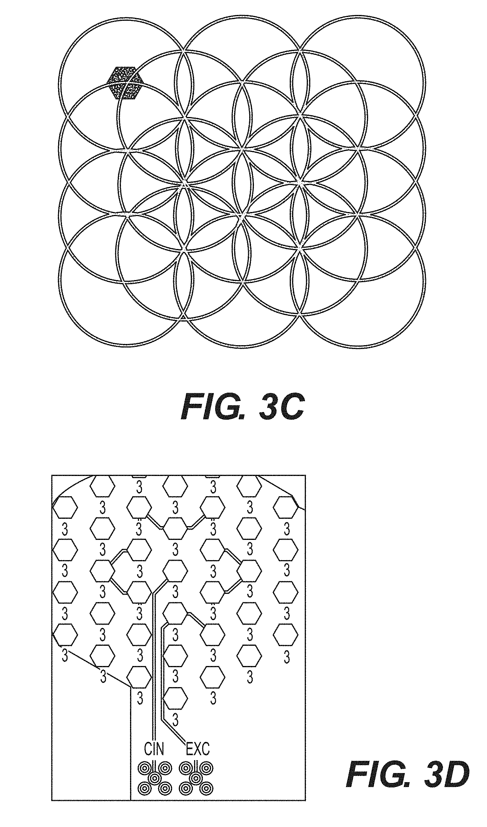
[0020] FIG. 3C--An exemplary array of hexagon pad electrodes where each of the electrodes may be programmed to function as different parts of a coaxial electrode in accordance with the present disclosure.
[0021] FIG. 3D--Sample electronic connection of an array of hexagonal pad electrodes allowing for coaxial electrode emulation in accordance with the present disclosure.
[0022] FIG. 3E--An exemplary array of coaxial electrodes electronically coupled together.
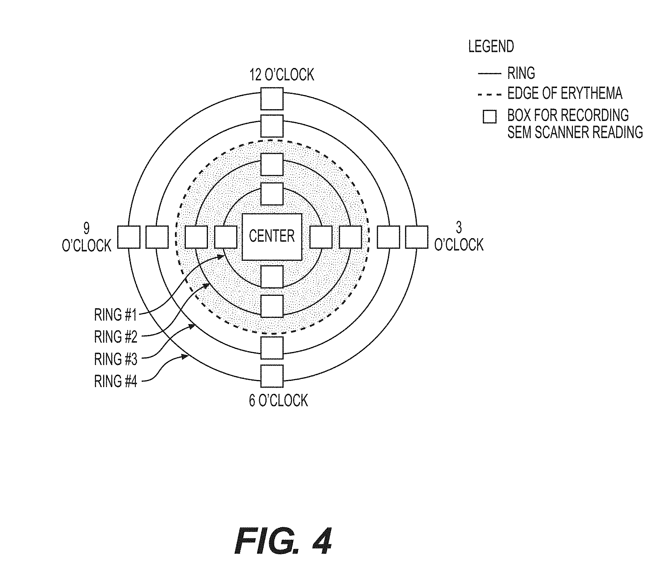
[0023] FIG. 4--A sample measurement scheme according to the present disclosure.
[0024] FIG. 5A--Sample SEM measurement results obtained in accordance with the methods in the present disclosure, represented as a SEM map.
[0025] FIG. 5B--Sample SEM measurement results along the x-axis of FIG. 5A plotted on a graph.
[0026] FIG. 5C--Sample SEM measurement results along the y-axis of FIG. 5A plotted on a graph.
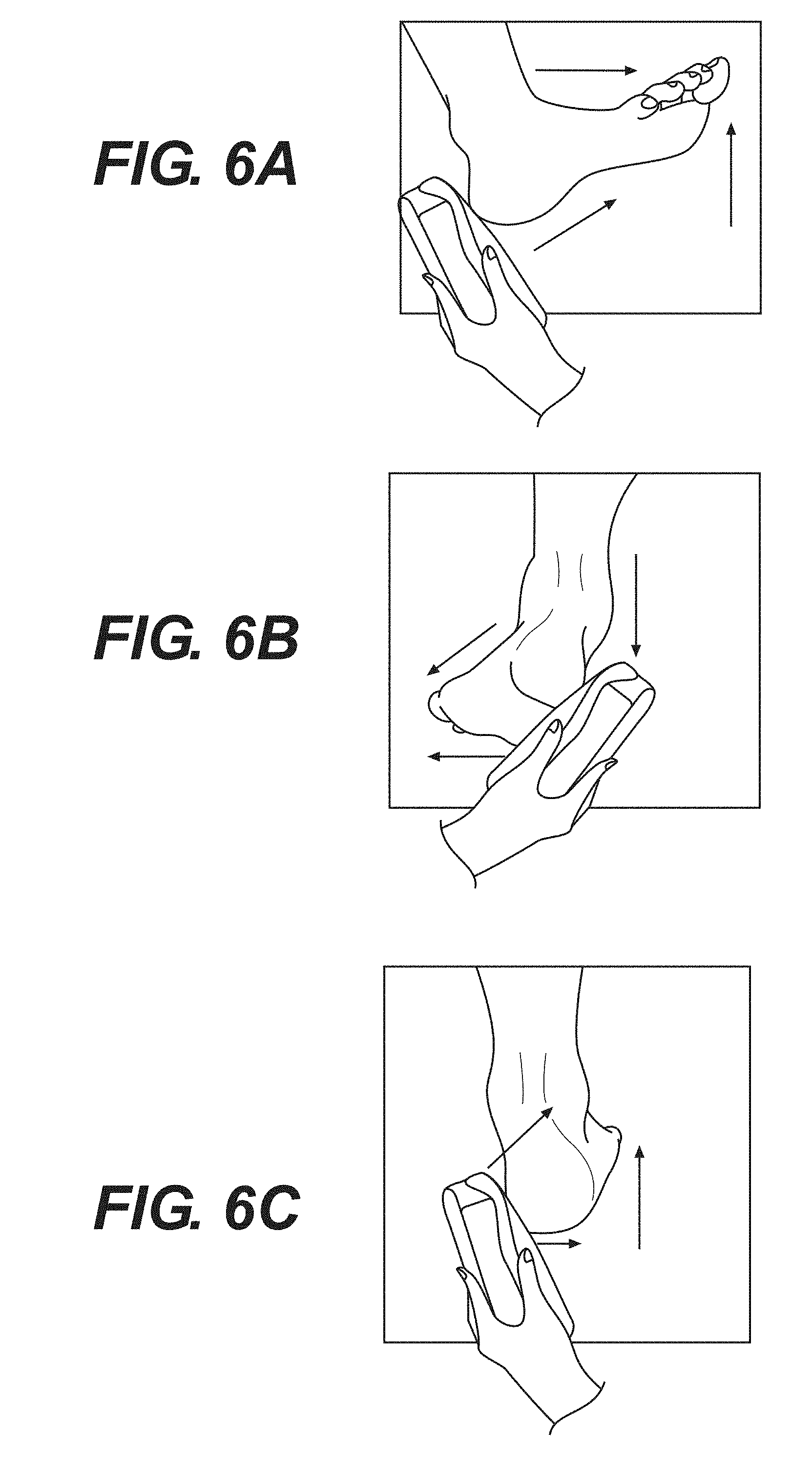
[0027] FIG. 6A--An exemplary method for taking SEM measurements starting at the posterior heel.
[0028] FIG. 6B--An exemplary method for taking SEM measurements starting at the lateral heel.
[0029] FIG. 6C--An exemplary method for taking SEM measurements starting at the medial heel.
[0030] FIG. 7A--Sample visual assessment of damaged tissue around a sacrum.
[0031] FIG. 7B--Sample SEM measurement results of damaged tissue obtained in accordance with the methods in the present disclosure.
[0032] FIG. 8A--Sample visual assessment of healthy tissue around a sacrum.
[0033] FIG. 8B--Sample SEM measurement results of healthy tissue obtained in accordance with the methods in the present disclosure.
[0034] FIG. 9A--A sample SEM map obtained in accordance with the methods in the present disclosure.
[0035] FIG. 9B--Corresponding visual assessment of damaged tissue of FIG. 9A.
[0036] FIG. 10--A sample SEM image obtained in accordance with the methods in the present disclosure.
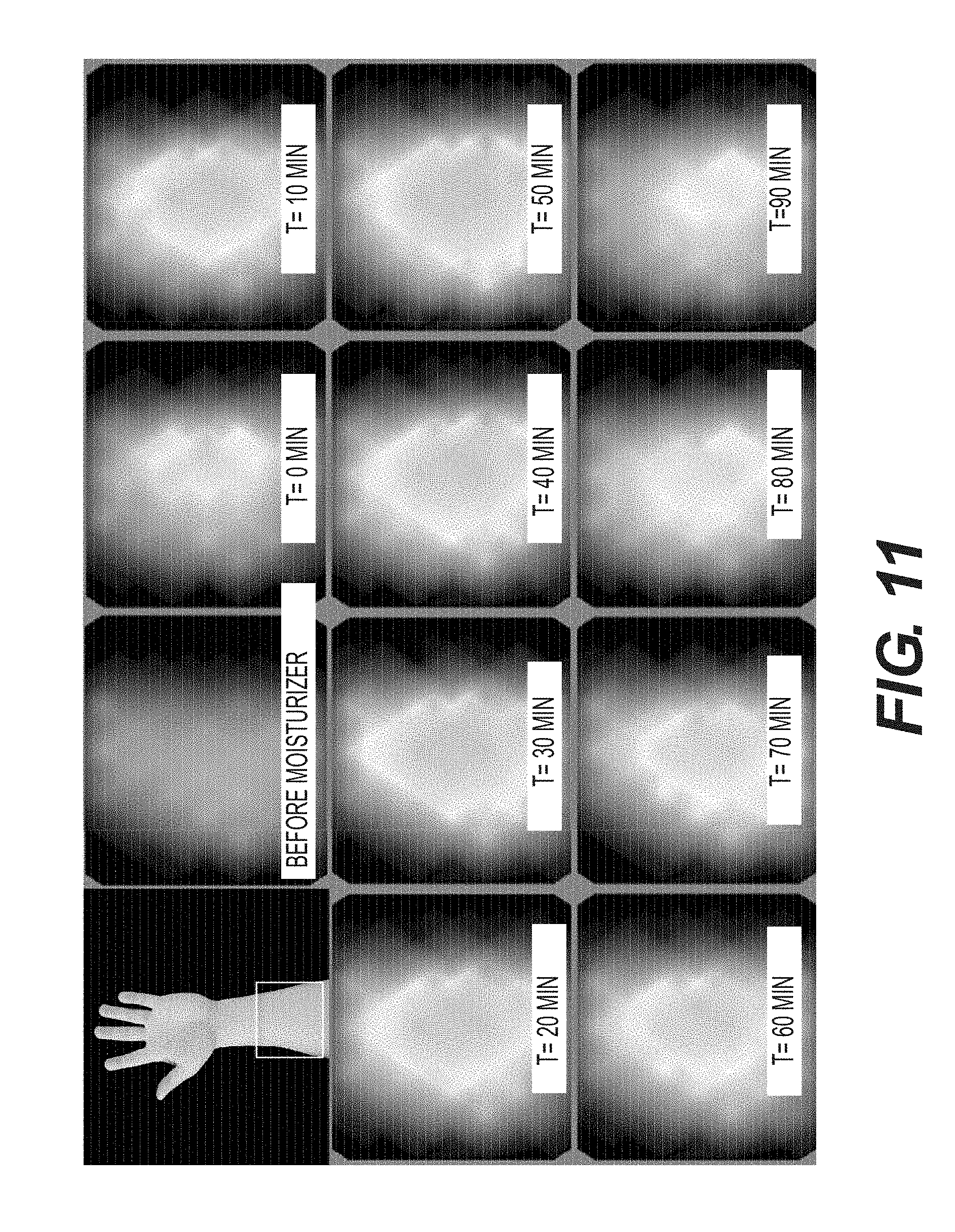
[0037] FIG. 11--Sample time-lapsed SEM images showing the sensitivity of the detection apparatuses and methods in the present disclosure.
[0038] FIG. 12A--A sample graphical representation of a finite element model showing the depth of various SEM levels in accordance with the methods in the present disclosure.
[0039] FIG. 12B--A sample plot of SEM measurements at various depth of a skin-like material.
DETAILED DESCRIPTION
[0040] This description is not intended to be a detailed catalog of all the different ways in which the disclosure may be implemented, or all the features that may be added to the instant disclosure. For example, features illustrated with respect to one embodiment may be incorporated into other embodiments, and features illustrated with respect to a particular embodiment may be deleted from that embodiment. Thus, the disclosure contemplates that in some embodiments of the disclosure, any feature or combination of features set forth herein can be excluded or omitted. In addition, numerous variations and additions to the various embodiments suggested herein will be apparent to those skilled in the art in light of the instant disclosure, which do not depart from the instant disclosure. In other instances, well-known structures, interfaces, and processes have not been shown in detail in order not to unnecessarily obscure the invention. It is intended that no part of this specification be construed to effect a disavowal of any part of the full scope of the invention. Hence, the following descriptions are intended to illustrate some particular embodiments of the disclosure, and not to exhaustively specify all permutations, combinations and variations thereof.
[0041] Unless otherwise defined, all technical and scientific terms used herein have the same meaning as commonly understood by one of ordinary skill in the art to which this disclosure belongs. The terminology used in the description of the disclosure herein is for the purpose of describing particular embodiments only and is not intended to be limiting of the disclosure.
[0042] All publications, patent applications, patents and other references cited herein are incorporated by reference in their entireties for the teachings relevant to the sentence and/or paragraph in which the reference is presented. References to techniques employed herein are intended to refer to the techniques as commonly understood in the art, including variations on those techniques or substitutions of equivalent techniques that would be apparent to one of skill in the art.
[0043] Unless the context indicates otherwise, it is specifically intended that the various features of the disclosure described herein can be used in any combination. Moreover, the present disclosure also contemplates that in some embodiments of the disclosure, any feature or combination of features set forth herein can be excluded or omitted.
[0044] The methods disclosed herein comprise one or more steps or actions for achieving the described method. The method steps and/or actions may be interchanged with one another without departing from the scope of the present invention. In other words, unless a specific order of steps or actions is required for proper operation of the embodiment, the order and/or use of specific steps and/or actions may be modified without departing from the scope of the present invention.
[0045] As used in the description of the disclosure and the appended claims, the singular forms "a," "an" and "the" are intended to include the plural forms as well, unless the context clearly indicates otherwise.
[0046] As used herein, "and/or" refers to and encompasses any and all possible combinations of one or more of the associated listed items, as well as the lack of combinations when interpreted in the alternative ("or").
[0047] The terms "about" and "approximately" as used herein when referring to a measurable value such as a length, a frequency, or a SEM value and the like, is meant to encompass variations of .+-.20%, .+-.10%, .+-.5%, .+-.1%, .+-.0.5%, or even .+-.0.1% of the specified amount.
[0048] As used herein, phrases such as "between X and Y" and "between about X and Y" should be interpreted to include X and Y. As used herein, phrases such as "between about X and Y" mean "between about X and about Y" and phrases such as "from about X to Y" mean "from about X to about Y."
[0049] The terms "comprise," "comprises," and "comprising" as used herein, specify the presence of the stated features, integers, steps, operations, elements, and/or components, but do not preclude the presence or addition of one or more other features, integers, steps, operations, elements, components, and/or groups thereof.
[0050] As used herein, the transitional phrase "consisting essentially of" means that the scope of a claim is to be interpreted to encompass the specified materials or steps recited in the claim and those that do not materially affect the basic and novel characteristic(s) of the claimed disclosure. Thus, the term "consisting essentially of" when used in a claim of this disclosure is not intended to be interpreted to be equivalent to "comprising."
[0051] As used herein, the term "sub-epidermal moisture" refers to the increase in tissue fluid and local edema caused by vascular leakiness and other changes that modify the underlying structure of the damaged tissue in the presence of continued pressure on tissue, apoptosis, necrosis, and the inflammatory process.
[0052] As used herein, a "system" may be a collection of devices in wired or wireless communication with each other.
[0053] As used herein, "interrogate" refers to the use of radiofrequency energy to penetrate into a patient's skin.
[0054] As used herein a "patient" may be a human or animal subject.
[0055] An exemplary apparatus according to the present disclosure is shown in FIGS. 1 and 2. It will be understood that these are examples of an apparatus for measuring sub-epidermal moisture ("SEM"). In some embodiments, the apparatus according to the present disclosure may be a handheld device, a portable device, a wired device, a wireless device, or a device that is fitted to measure a part of a human patient. U.S. Publication No. 2014/0288397 A1 to Sarrafzadeh et al. is directed to a SEM scanning apparatus, which is incorporated herein by reference in its entirety.
[0056] In certain embodiments according to the present disclosure, the apparatus may comprise one or more electrodes. In one aspect according to the present disclosure, it may be preferable to use coaxial electrodes over electrodes such as tetrapolar ECG electrodes because coaxial electrodes are generally isotropic, which may allow SEM values to be taken irrespective of the direction of electrode placement. The SEM values measured by coaxial electrodes may also be representative of the moisture content of the tissue underneath the coaxial electrodes, rather than the moisture content of the tissue surface across two bi-polar electrodes spaced apart. In some embodiments, the apparatus may comprise two or more coaxial electrodes, three or more coaxial electrodes, four or more coaxial electrodes, five or more coaxial electrodes, ten or more coaxial electrodes, fifteen or more coaxial electrodes, twenty or more coaxial electrodes, twenty five or more coaxial electrodes, or thirty or more coaxial electrodes. In some embodiments, the aforementioned coaxial electrodes may be configured to emit and receive an RF signal at a frequency of 32 kilohertz (kHz). In other embodiments, the coaxial electrodes may be configured to emit and receive an RF signal at a frequency of from about 5 kHz to about 100 kHz, from about 10 kHz to about 100 kHz, from about 20 kHz to about 100 kHz, from about 30 kHz to about 100 kHz, from about 40 kHz to about 100 kHz, from about 50 kHz to about 100 kHz, from about 60 kHz to about 100 kHz, from about 70 kHz to about 100 kHz, from about 80 kHz to about 100 kHz, or from about 90 kHz to about 100 kHz. In yet another embodiment, the coaxial electrodes may be configured to emit and receive an RF signal at a frequency of from about 5 kHz to about 10 kHz, from about 5 kHz to about 20 kHz, from about 5 kHz to about 30 kHz, from about 5 kHz to about 40 kHz, from about 5 kHz to about 50 kHz, from about 5 kHz to about 60 kHz, from about 5 kHz to about 70 kHz, from about 5 kHz to about 80 kHz, or from about 5 kHz to about 90 kHz. In a further embodiment, the coaxial electrodes may be configured to emit and receive an RF signal at a frequency less than 100 kHz, less than 90 kHz, less than 80 kHz, less than 70 kHz, less than 60 kHz, less than 50 kHz, less than 40 kHz, less than 30 kHz, less than 20 kHz, less than 10 kHz, or less than 5 kHz. In certain embodiments, all of the coaxial electrodes of the apparatus may operate at the same frequency. In some embodiments, some of the coaxial electrodes of the apparatus may operate at different frequencies. In certain embodiments, the frequency of a coaxial electrode may be changed through programming specific pins on an integrated circuit in which they are connected.
[0057] In some embodiments according to the present disclosure, the coaxial electrodes may comprise a bipolar configuration having a first electrode comprising an outer annular ring disposed around a second inner circular electrode. Referring to FIG. 3A, the outer ring electrode may have an outer diameter D.sub.o and an inner diameter D.sub.I that is larger than the diameter D.sub.c of the circular inner electrode. Each inner circular electrode and outer electrode may be coupled electrically to one or more circuits that are capable of applying a voltage waveform to each electrode; generating a bioimpedance signal; and converting the capacitance signal to a SEM value. In certain embodiments, the bioimpedance signal may be a capacitance signal generated by, e.g., measuring the difference of the current waveform applied between the central electrode and the annular ring electrode. In some embodiments, the conversion may be performed by a 24 bit capacitance-to-digital converter. In another embodiment, the conversion may be a 16 bit capacitance-to-digital converter, a charge-timing capacitance to digital converter, a sigma-delta capacitance to digital converter. The one or more circuits may be electronically coupled to a processor. The processor may be configured to receive the SEM value generated by the circuit.
[0058] In certain embodiments, the one or more coaxial electrodes may have the same size. In other embodiments, the one or more coaxial electrodes may have different sizes, which may be configured to interrogate the patient's skin at different depths. The dimensions of the one or more coaxial electrodes may correspond to the depth of interrogation into the derma of the patient. Accordingly, a larger diameter electrode may penetrate deeper into the skin than a smaller pad. The desired depth may vary depending on the region of the body being scanned, or the age, skin anatomy or other characteristic of the patient. In some embodiments, the one or more coaxial electrodes may be coupled to two or more separate circuits to allow independent operation of each of the coaxial electrodes. In another embodiment, all, or a subset, of the one or more coaxial electrodes may be coupled to the same circuit.
[0059] In some embodiments, the one or more coaxial electrodes may be capable of emitting RF energy to a skin depth of 4 millimeters (mm), 3.5 mm, 3.0 mm, 2.5 mm, 2.0 mm, 1.0 mm, or 0.5 mm. In a further embodiment, the one or more coaxial electrodes may have an outer diameter D.sub.o from about 5 mm to about 55 mm, from about 10 mm to about 50 mm, from about 15 mm to about 45 mm, or from about 20 mm to about 40 mm. In another embodiment, the outer ring of the one or more coaxial electrodes may have an inner diameter D.sub.I from about 4 mm to about 40 mm, from about 9 mm to about 30 mm, or from about 14 mm to about 25 mm. In yet another embodiment, the inner electrode of the one or more coaxial electrodes may have a diameter D.sub.c from about 2 mm to 7 mm, 3 mm to 6 mm, or 4 mm to 5 mm.
[0060] In a further embodiment, the one or more coaxial electrodes may be spaced apart at a distance to avoid interference between the electrodes. The distance may be a function of sensor size and frequency to be applied. In some embodiments, each of the one or more coaxial electrodes may be activated sequentially. In certain embodiments, multiple coaxial electrodes may be activated at the same time.
[0061] In certain embodiments according to the present disclosure, a coaxial electrode may comprise a point source surrounded by hexagon pad electrodes spaced at approximately equidistance, as illustrated in FIG. 3B. The point source may comprise a hexagon pad electrode. In some embodiments, the point source may comprise two, three, four, five, or six hexagon pad electrodes. In certain embodiments, a point source may be surrounded by six hexagon pad electrodes. In some embodiments, multiple coaxial electrodes may be emulated from an array comprising a plurality of hexagon pad electrodes, where each hexagon pad electrode may be programmed to be electronically coupled to a floating ground, a capacitance input, or a capacitance excitation signal, as illustrated in FIGS. 3C and 3D. In a further embodiment, each of the hexagon pad electrodes may be connected to a multiplexer that may have a select line that controls whether the hexagon pad electrode is connected to a capacitance input or a capacitance excitation signal. The multiplexer may also have an enable line that controls whether to connect the hexagon pad electrode to a floating ground. In certain embodiments, the multiplexer may be a pass-gate multiplexer. In some embodiments, the one or more coaxial electrodes may be arranged as illustrated in FIG. 3E to leverage multiplexer technology. Without being limited to theory, the arrangement illustrated in FIG. 3E may limit interference between the one or more coaxial electrodes.
[0062] In certain embodiments, one or more coaxial electrodes may be embedded on a first side of a non-conductive substrate. In some embodiments, the substrate may be flexible or hard. In certain embodiments, the flexible substrate may comprise kapton, polyimide, or a combination thereof. In further embodiments, an upper coverlay may be positioned directly above the one or more coaxial electrodes. In certain embodiments, the upper coverlay may be a double-sided, copper-clad laminate and an all-polyimide composite of a polyimide film bonded to copper foil. In some embodiments, the upper coverlay may comprise Pyralux 5 mil FR0150. Without being limited by theory, the use this upper coverlay may avoid parasitic charges naturally present on the skin surface from interfering with the accuracy and precision of SEM measurements. In some embodiments, the one or more coaxial electrodes may be spring mounted to a substrate within an apparatus according to the present disclosure.
[0063] In some embodiments, the apparatus may comprise a non-transitory computer readable medium electronically coupled to the processor. In certain embodiments, the non-transitory computer readable medium may comprise instructions stored thereon that, when executed on a processor, may perform the steps of: (1) receiving at least one SEM value at an anatomical site; (2) receiving at least two SEM values measured around the anatomical site and their relative measurement locations; (3) determining a maximum SEM value from the measurements around the anatomical site; (4) determining a difference between the maximum SEM value and each of the at least two SEM values measured around the anatomical site; and (5) flagging the relative measurement locations associated with a difference greater than a predetermined value as damaged tissue. In another embodiment, the non-transitory computer readable medium may comprise instructions stored thereon that may carry out the following steps when executed by the processor: (1) receiving at least one SEM value measured at an anatomical site; (2) receiving at least two SEM values measured around the anatomical site, and their relative measurement locations; (3) determining an average SEM value for each group of SEM values measured at approximately equidistance from the anatomical site; (4) determining a maximum SEM value from the average SEM values; (5) determining a difference between the maximum average SEM value and each of the average SEM values measured around the anatomical site; and (6) flagging the relative measurement locations associated with a difference greater than a predetermined value as damaged tissue. In yet another embodiment, the non-transitory computer readable medium may comprise instructions stored thereon that, when executed on a processor, may perform the steps of: (1) receiving at least one SEM value at an anatomical site; (2) receiving at least two SEM values measured around the anatomical site and their relative measurement locations; (3) determining a maximum SEM value from the measurements around the anatomical site; (4) determining a minimum SEM value from the measurements around the anatomical site; (5) determining a difference between the maximum SEM value and the minimum SEM value; and (6) flagging the relative measurement locations associated with a difference greater than a predetermined value as damaged tissue. In some embodiments, the predetermined value may be 0.3, 0.35, 0.4, 0.45, 0.5, 0.55, 0.6, 0.65, 0.7, 0.75, 0.8, 0.85, 0.9, 0.95, 1.0, 1.1, 1.2, 1.3, 1.4, 1.5, 1.6, 1.7, 1.8, 1.9, 2.0, 2.1, 2.2, 2.3, 2.4, 2.5, 2.6, 2.7, 2.8, 2.9, 3.0, 3.1, 3.2, 3.3, 3.4, 3.5, 3.6, 3.7, 3.8, 3.9, 4.0, 4.1, 4.2, 4.3, 4.4, 4.5, 4.6, 4.7, 4.8, 4.9, 5.0, 5.1, 5.2, 5.3, 5.4, 5.5, 5.6, 5.7, 5.8, 5.9, 6.0, 6.1, 6.2, 6.3, 6.4, 6.5, 6.6, 6.7, 6.8, 6.9, 7.0, 7.1, 7.2, 7.3, 7.4, or 7.5. It will be understood that the predetermined value is not limited by design, but rather, one of ordinary skill in the art would be capable of choosing a predetermined value based on a given unit of SEM.
[0064] In further embodiments, the leading edge of inflammation may be indicated by an SEM difference that is equal to or greater than the predetermined value. In some embodiments, the leading edge of inflammation may be identified by the maximum values out of a set of SEM measurements.
[0065] In certain embodiments, an anatomical site may be a bony prominence. In further embodiments, an anatomical site may be a sternum, sacrum, a heel, a scapula, an elbow, an ear, or other fleshy tissue. In some embodiments, one SEM value is measured at the anatomical site. In another embodiment, an average SEM value at the anatomical site is obtained from two, three, four, five, six, seven, eight, nine, ten, or more than ten SEM values measured at the anatomical site.
[0066] The apparatuses of the present disclosure may allow the user to control the pressure applied onto a patient's skin to allow for optimized measurement conditions. In certain embodiments, a first pressure sensor may be placed on a second side opposing the first side of the substrate that the coaxial electrodes are disposed on. In a further embodiment, a second pressure sensor may be disposed on a second side opposing the first side of the substrate that the coaxial electrodes are disposed on. In certain embodiments, the first pressure sensor may be a low pressure sensor, and the second pressure sensor may be a high pressure sensor. Together, the first and second pressure sensors may allow measurements to be taken at a predetermined range of target pressures. In some embodiments, a target pressure may be about 500 g. It will be understood that the high and low pressure sensors are not limited by design, but rather, one of ordinary skill in the art would be capable of choosing these sensors based on a given range of target pressures. The first and second pressure sensors may be resistive pressure sensors. In some embodiments, the first and second pressure sensors may be sandwiched between the substrate and a conformal pressure pad. The conformal pressure pad may provide both support and conformity to enable measurements over body curvature and bony prominences.
[0067] In an embodiment, the apparatus may further comprise a plurality of contact sensors on the same planar surface as, and surrounding, each of the one or more coaxial electrodes to ensure complete contact of the one or more coaxial electrodes to the skin surface. The plurality of contact sensors may be a plurality of pressure sensors, a plurality of light sensors, a plurality of temperature sensors, a plurality of pH sensors, a plurality of perspiration sensors, a plurality of ultrasonic sensors, a plurality of bone growth stimulator sensors, or a plurality of a combination of these sensors. In some embodiments, the plurality of contact sensors may comprise four, five, six, seven, eight, nine, or ten or more contact sensors surrounding the one or more coaxial electrodes.
[0068] In certain embodiments, the apparatus may comprise a temperature probe. In some embodiments, the temperature probe may be a thermocouple or an infrared thermometer.
[0069] In some embodiments, the apparatus may further comprise a display having a user interface. The user interface may allow the user to input measurement location data. The user interface may further allow the user to view measured SEM values and/or damaged tissue locations. In certain embodiments, the apparatus may further comprise a transceiver circuit configured to receive data from and transmit data to a remote device, such as a computer, tablet or other mobile or wearable device. The transceiver circuit may allow for any suitable form of wired or wireless data transmission such as, for example, USB, Bluetooth, or Wifi.
[0070] Methods according to the present disclosure provide for identifying damaged tissue. In some embodiments, the method may comprise measuring at least three SEM values at and around an anatomical site using an apparatus of the present invention, and obtaining from the apparatus measurement locations that are flagged as damaged tissue. In certain embodiments, measurements may be taken at positions that are located on one or more concentric circles about an anatomic site. FIG. 4 provides a sample measurement strategy, with the center being defined by an anatomic site. In another embodiments, the measurements may be taken spatially apart from an anatomic site. In yet another embodiment, the measurements may be taken on a straight line across an anatomic site. In a further embodiment, the measurements may be taken on a curve around an anatomic site. In certain embodiment, surface moisture and matter above a patient's skin surface may be removed prior to the measuring step. In some embodiments, the measuring step may take less than one second, less than two seconds, less than three seconds, less than four seconds, or less than five seconds.
[0071] Having now generally described the invention, the same will be more readily understood through reference to the following examples that are provided by way of illustration, and are not intended to be limiting of the present disclosure, unless specified.
EXAMPLES
Example 1
Measuring Sub-Epidermal Moisture (SEM) Values at the Bony Prominence of the Sacrum
[0072] Subjects with visually-confirmed Stage I or II pressure ulcers with unbroken skin were subjected to multiple SEM measurements at and around the boney prominence of the sacrum using an apparatus of this disclosure. Prior to performing the measurements, surface moisture and matter above the subjects' skin surface were removed. An electrode of the apparatus was applied to the desired anatomical site with sufficient pressure to ensure complete contact for approximately one second. Additional measurements were taken at the mapped location as laid out in FIG. 4.
[0073] FIG. 5A shows a sample SEM map centered on an anatomical site. FIG. 5B is a plot of the individual SEM values across the x-axis of the SEM map. FIG. 5C is a plot of the individual SEM values across the y-axis of the SEM map. Damaged tissue radiated from the center anatomical site to an edge of erythema defined by a difference in SEM values of greater than 0.5.
Example 2
Taking SEM Measurements at the Bony Prominence of the Heel
[0074] SEM measurements were taken at the heel using one of three methods below to ensure complete contact of an electrode with the skin of a human patient.
[0075] FIG. 6A illustrates a method used to take SEM measurements starting at the posterior heel using an apparatus according to the present disclosure. First, the forefoot was dorsiflexed such that the toes were pointing towards the shin. Second, an electrode was positioned at the base of the heel. The electrode was adjusted for full contact with the heel, and multiple SEM measurements were then taken in a straight line towards the toes.
[0076] FIG. 6B illustrates a method used to take SEM measurements starting at the lateral heel using an apparatus according to the present disclosure. First, the toes were pointed away from the body and rotated inward towards the medial side of the body. Second, an electrode was placed on the lateral side of the heel. The electrode was adjusted for full contact with the heel, and multiple SEM measurements were taken in a straight line towards the bottom of the foot.
[0077] FIG. 6C illustrates a method used to take SEM measurements starting at the medial heel using an apparatus according to the present disclosure. First, the toes were pointed away from the body and rotated outwards toward the lateral side of the body. Second, the electrode was placed on the medial side of the heel. The electrode was adjusted for full contact with the heel, and multiple measurements were taken around the back of the heel in a curve.
Example 3
Identifying a Region of Damaged Tissue
[0078] SEM measurements were taken on a straight line, each spaced apart by 2 cm, across the sacrum of a patient. Multiple measurements were taken at a given measurement location. FIG. 7A is a sample visual assessment of damaged tissue. FIG. 7B is a corresponding plot of the averages of SEM measurements taken at each location. The edges of erythema are defined by differences in SEM values of greater than 0.5.
Example 4
SEM Measurements of Healthy Tissue
[0079] SEM measurements were taken on a straight line across the sacrum of a patient. Multiple measurements were taken at a given measurement location. FIG. 8A is a sample visual assessment of healthy tissue. FIG. 8B is a corresponding plot of the averages of SEM measurements taken at each location. The tissue is defined as healthy as the differences in SEM values are all less than 0.5.
Example 5
SEM Measurement Map of Damaged Tissue
[0080] SEM measurements were taken in accordance with Example 1. FIG. 9A is a sample map of averaged SEM values taken on concentric rings around an anatomical site. FIG. 9B is the corresponding visual assessment of the patient's skin. Compromised tissue is identified by the solid circle, where the difference in SEM values compared to the maximum SEM value is greater than 0.5. The leading edge of inflammation is identified by the dotted circle, where the difference in SEM values compared to the maximum SEM value is equal to or greater than 0.5. The leading edge of inflammation is identified by a dotted line, indicating the largest values in the SEM map.
Example 6
Sample SEM Measurement Image Representations
[0081] SEM measurements were taken with an array of coaxial electrodes. FIG. 10 is a sample output of a SEM measurement image showing the moisture content of the skin over a defined area. Different SEM values are indicated by different colors.
Example 7
SEM Measurements of Skin Moisture Content Over Time
[0082] Moisturizer was used to simulate the onset of a pressure ulcer. 0.2 mL moisturizer was applied to the inner forearm of a subject for 60 seconds. The moisturizer was then wiped from the skin. SEM measurements were taken with an array of coaxial electrodes every 10 minutes for 2 hours. FIG. 11 shows a sample time lapse of an SEM measurement image to monitor moisture content of a test subject.
Example 8
Selecting an Optimal Electrode for Interrogating Patient Skin
[0083] FIG. 12A is a sample graphical representation of a finite element model showing the depth of various SEM levels in accordance with the methods in the present disclosure. Each line indicates a SEM value and the depth of the moisture content.
[0084] Actual SEM levels in various depths of a skin-like material were measured using an apparatus according to the present disclosure. Specifically, the apparatus comprises one coaxial electrode. First, the thickness of a blister bandage, which simulates a skin-like material, was measured and placed on the coaxial electrode. A downward force was then applied via a metal onto the coaxial electrode, in an acceptable range according to the present disclosure. The metal is fitted to a second metal in tubular form. The second metal was selected from brass, aluminum, and stainless steel. The SEM measurement was recorded. Additional blister bandages were placed atop the coaxial electrodes for further SEM measurement recordings. FIG. 12B is a sample plot of SEM measurements at various thicknesses of the blister bandages. Without being limited by theory, the variations in the SEM values in the presence of different tubular metal may be due to potential magnetic field interference. The maximum depth of a magnetic field generated by the coaxial sensor was determined by the distance from the coaxial sensor when the metal tube no longer interfered with the magnetic field. In this example, the maximum depth ranged from 0.135 inches to 0.145 inches. Accordingly, electrodes having an optimal penetration depth could be selected to interrogate specific depths of patient skin.
[0085] While the invention has been described with reference to particular embodiments, it will be understood by those skilled in the art that various changes may be made and equivalents may be substituted for elements thereof without departing from the scope of the invention. In addition, many modifications may be made to a particular situation or material to the teachings of the invention without departing from the scope of the invention.
[0086] Therefore, it is intended that the invention not be limited to the particular embodiments disclosed as the best mode contemplated for carrying out this invention, but that the invention will include all embodiments falling within the scope and spirit of the appended claims.
* * * * *
D00000
D00001
D00002
D00003
D00004
D00005
D00006
D00007
D00008
D00009
D00010
D00011
D00012

D00013

D00014
D00015

D00016

XML
uspto.report is an independent third-party trademark research tool that is not affiliated, endorsed, or sponsored by the United States Patent and Trademark Office (USPTO) or any other governmental organization. The information provided by uspto.report is based on publicly available data at the time of writing and is intended for informational purposes only.
While we strive to provide accurate and up-to-date information, we do not guarantee the accuracy, completeness, reliability, or suitability of the information displayed on this site. The use of this site is at your own risk. Any reliance you place on such information is therefore strictly at your own risk.
All official trademark data, including owner information, should be verified by visiting the official USPTO website at www.uspto.gov. This site is not intended to replace professional legal advice and should not be used as a substitute for consulting with a legal professional who is knowledgeable about trademark law.