Solid Dispenser
JAIN; Vipin ; et al.
U.S. patent application number 16/051052 was filed with the patent office on 2019-10-10 for solid dispenser. The applicant listed for this patent is 6D Bytes Inc.. Invention is credited to Venkateswaran AYALUR, Vijayasimha DODDABALAPUR, Vipin JAIN.
| Application Number | 20190307262 16/051052 |
| Document ID | / |
| Family ID | 68096012 |
| Filed Date | 2019-10-10 |


View All Diagrams
| United States Patent Application | 20190307262 |
| Kind Code | A1 |
| JAIN; Vipin ; et al. | October 10, 2019 |
Solid Dispenser
Abstract
In one embodiment, the present disclosure includes a solid dispenser comprising a dispensing element and a housing. The dispensing element includes a plurality of blades extending from a cylindrical base. In one example embodiment, the blades are separated by 90 degrees to form channels from an upper opening in the housing to a lower opening in the housing. A hopper for storing items to be dispensed may be configured on one side of the dispenser, and a trap for controlling the flow of dispensed items may be configured on the other side of the dispenser. In one embodiment, the dispenser is controlled by motors coupled to a server as part of a fully automated cloud controlled robotic food preparation system, where each dispenser may accurately deliver different quantities of ingredients for different orders.
| Inventors: | JAIN; Vipin; (Saratoga, CA) ; AYALUR; Venkateswaran; (Cupertino, CA) ; DODDABALAPUR; Vijayasimha; (Foster City, CA) | ||||||||||
| Applicant: |
|
||||||||||
|---|---|---|---|---|---|---|---|---|---|---|---|
| Family ID: | 68096012 | ||||||||||
| Appl. No.: | 16/051052 | ||||||||||
| Filed: | July 31, 2018 |
Related U.S. Patent Documents
| Application Number | Filing Date | Patent Number | ||
|---|---|---|---|---|
| 62652740 | Apr 4, 2018 | |||
| Current U.S. Class: | 1/1 |
| Current CPC Class: | B65D 25/38 20130101; B65D 83/06 20130101; B25J 9/161 20130101; B25J 15/0608 20130101; B25J 9/0096 20130101; B25J 13/006 20130101; B25J 21/00 20130101; B65D 47/04 20130101; G01G 13/026 20130101; A47J 43/0722 20130101; G05B 2219/40 20130101; A47F 10/06 20130101; B25J 9/1602 20130101; B25J 11/00 20130101; G01F 11/261 20130101; A47G 19/34 20130101; B67D 1/06 20130101; B25J 11/0045 20130101; B25J 9/1661 20130101; G06F 40/30 20200101; B65G 65/4881 20130101; G01F 13/001 20130101; B65G 3/04 20130101; B67D 1/0041 20130101; B67D 1/0888 20130101; B67D 2210/00144 20130101; G01F 13/005 20130101; G05B 19/4147 20130101; B67D 2210/00076 20130101; A47F 1/035 20130101 |
| International Class: | A47F 1/035 20060101 A47F001/035; B65G 65/48 20060101 B65G065/48; G01G 13/02 20060101 G01G013/02 |
Claims
1. An apparatus comprising: a hopper to hold ingredients; and a dispenser unit coupled below the hopper to receive the ingredients through an opening in the hopper, the dispenser unit comprising a housing and a dispenser element, the dispenser element coupled rotationally about a horizontal axis, the dispenser element having a first and second channels about the horizontal axis, wherein the dispenser element and the hopper couple such that the first and second channels may be selectively rotated dispense ingredients.
2. The apparatus of claim 1 further comprising a trap coupled below the dispenser unit, the trap comprising a flap having a first position and a second position, wherein in the first position the flap prevents ingredients from the dispenser unit from passing through the trap, and in a second position the flap produces an opening allowing ingredients from the dispenser unit to pass through the trap.
3. The apparatus of claim 1 wherein the first and second channels are formed from four blades emanating from a cylindrical base about the horizontal axis, wherein the blades emanate at 90 degrees from each other along the length of the cylindrical base, and wherein two adjacent blades of the four blades form the first channel and the other two adjacent blades of the four blades form the second channel.
4. The apparatus of claim 3 wherein the first and second channels curve along the horizontal axis such that the first and second channels shift by 90 degrees from a proximate end to a distal end of the dispenser element.
5. The apparatus of claim 1 wherein the first channel may be selectively rotated between first and second degrees into a first position to produce a first opening between the first channel and the opening in the hopper, and in accordance therewith, a first amount of the ingredients enter the first channel.
6. The apparatus of claim 5 wherein the second channel may be selectively rotated into a second position to produce a second opening between the second channel and the opening in the hopper, and in accordance therewith, a second amount of the ingredients enter the second channel.
7. The apparatus of claim 6 wherein the dispenser element is rotated so that the first and second openings are approximately the same.
8. The apparatus of claim 6 wherein a rotation to generate the first or second openings is determined by a predetermined calibration factor corresponding to at least a size of the first or second channels, a desired amount of the ingredients, and a cut size of the ingredients.
9. The apparatus of claim 6 wherein the first and second channels may be selectively rotated into a third position allowing the first amount of ingredients to fall out of the first channel, and wherein the first and second channels may be selectively rotated into a fourth position allowing the second amount of ingredients to fall out of the second channel.
10. The apparatus of claim 9 wherein the first amount of ingredients is an incremental amount, and wherein the dispenser element rotates between a plurality of positions for a predetermined number of cycles to provide a final amount of the ingredients.
11. The apparatus of claim 1 further comprising a scale to measure a weight of dispensed ingredients, wherein a value measured by the scale is used to recalculate a number of cycles of rotation to dispense a final amount of the ingredients.
12. An apparatus comprising: a housing having upper opening for receiving ingredients to be dispensed and a lower opening for dispensing the ingredients; and a dispenser element comprising four blades configured 90 degrees from each other around a central cylinder and curved along a length of the cylinder by a 90 degrees to create a first channel and a second channel between the upper opening and lower opening, wherein the blades are rotated between first and second positions to control the flow of ingredients from the upper opening through the first and second channels and to the lower opening.
13. The apparatus of claim 12 wherein, for a first size of ingredients, the cylinder has a first diameter and the blades have a first radial length, and wherein for a second size of ingredients greater than the first size of ingredients, the cylinder has a second diameter and the blades have a second radial length, and wherein the first diameter is greater than the second diameter and the first radial length is less than the second radial length.
14. The apparatus of claim 12 further comprising: a hopper coupled to the upper opening; and a trap coupled to the lower opening.
15. The apparatus of claim 12 further comprising a first motor coupled to rotate the dispenser element and produce the flow of ingredients.
16. The apparatus of claim 12 further comprising: a controller coupled to control the first motor; a second motor coupled to a trap and further coupled to the controller to open and close the trap; and a server coupled to the controller, wherein in response to a command from the server to the controller to dispense, the controller configures the motor to open the trap, and wherein the controller closes the trap prior to responding to the server that the dispense operation is completed.
17. The apparatus of claim 16 further comprising: a receptacle positioned below the trap to receive the ingredients exiting the trap; and a scale coupled to the receptacle to measure a weight of the ingredients located within the receptacle.
18. The apparatus of claim 17 wherein the scale provides a feedback signal to the controller such that the dispenser element responds to the weight of ingredients within the receptacle to deliver a weight of ingredients specified in an instruction received by the controller from a server.
19. The apparatus of claim 18 wherein the controller provides a feedback signal to the server such that the server responds to the weight of ingredients within the receptacle to configure the controller to dispense an updated weight of ingredients.
20. The apparatus of claim 16 wherein an initial calibration factor is loaded from the server to the controller to set a rotation value and a cycle value to deliver the desired weight of the items.
Description
CROSS REFERENCE TO RELATED APPLICATIONS
[0001] This application claims the benefit of priority to U.S. Provisional Patent Application No. 62/652,740, filed Apr. 4, 2018, the entire contents of which are incorporated herein by reference.
BACKGROUND
[0002] The present disclosure relates to apparatuses, systems, and methods of solid dispensing, and in some embodiments, to a computer controlled solid dispenser for an automated robotic system.
[0003] Dispensers are typically used to store and deliver items. One challenge with creating a reliable dispenser is the ability to control the amount of material that is delivered. This is particularly challenging when the material is food, for example, such as solid chucks of fruits. Another challenge with creating a reliable dispenser is that the materials cannot get stuck inside the system. For automated delivery systems, ensuring that there are no jams and that repeatable quantities of materials can be delivered reliably may be paramount.
[0004] The present disclosure introduces a solid dispenser mechanism that may be used to reliably deliver repeatable quantities of items, such as food items.
SUMMARY
[0005] In one embodiment, the present disclosure includes a solid dispenser comprising a dispensing element and a housing. The dispensing element includes a plurality of blades extending from a cylindrical base. In one example embodiment, the blades are separated by 90 degrees to form channels from an upper opening in the housing to a lower opening in the housing. A hopper for storing items to be dispensed may be configured on one side of the dispenser, and a trap for controlling the flow of dispensed items may be configured on the other side of the dispenser. In one embodiment, the dispenser is controlled by motors coupled to a server as part of a fully automated cloud controlled robotic food preparation system, where each dispenser may accurately deliver different quantities of ingredients for different orders.
[0006] The following detailed description and accompanying drawings provide a better understanding of the nature and advantages of the present disclosure.
BRIEF DESCRIPTION OF THE DRAWINGS
[0007] FIG. 1 illustrates a dispenser apparatus according to one embodiment.
[0008] FIG. 2 illustrates another view of a dispenser unit coupled to a trap unit according to another embodiment.
[0009] FIG. 3 illustrates an example trap according to one embodiment.
[0010] FIG. 4 illustrates a dispenser unit according to one embodiment.
[0011] FIG. 5 illustrates the dispenser element according to one embodiment.
[0012] FIG. 6 illustrates a dispenser element in a first threshold position according to one embodiment.
[0013] FIG. 7 illustrates a dispenser element in a second threshold position according to one embodiment.
[0014] FIG. 8 illustrates a top view of a food dispenser apparatus according to one embodiment.
[0015] FIG. 9 illustrates a top view of an ingredient dispenser apparatus according to one embodiment.
[0016] FIG. 10 illustrates another example dispenser element 1000 according to another embodiment.
[0017] FIG. 11 illustrates a fully automated computer controlled dispenser system according to an embodiment.
DETAILED DESCRIPTION
[0018] In the following description, for purposes of explanation, numerous examples and specific details are set forth in order to provide a thorough understanding of the present disclosure. Such examples and details are not to be construed as unduly limiting the elements of the claims or the claimed subject matter as a whole. It will be evident to one skilled in the art, based on the language of the different claims, that the claimed subject matter may include some or all of the features in these examples, alone or in combination, and may further include modifications and equivalents of the features and techniques described herein.
[0019] FIG. 1 illustrates a dispenser apparatus according to one embodiment. The dispenser apparatus may include a hopper 110, a dispenser unit 120, and a trap unit 130, for example. The dispenser unit may be coupled to the hopper to receive the components to be dispensed. In this example, the trap is configured below the dispenser and the hopper 110 is configured above the dispenser 120. The hopper 110 is coupled to the dispenser 120 at an opening 111 in the bottom of the hopper 110 and a corresponding opening in the top of the dispenser 120 described in more detail below.
[0020] The hopper may hold components to be dispensed (aka ingredients), such as food ingredients, for example. The food ingredients may be frozen or fresh ingredients, either whole pieces or with different size cuts, for example. In this example, the hopper includes a minor incline 112 and major incline 113. An upper opening in the top of the hopper 110 may be larger than the lower opening 111 in the bottom of the hopper so that the hopper can hold a larger amount of ingredients to be dispensed, for example. In this example, the major incline 113 directs the ingredients from at least one side of the hopper 110 toward one side of the lower opening 111 in the bottom of the hopper. Additionally, in this example, the minor incline 112 directs the ingredients from at least another side of the hopper 110 toward one side of the lower opening 111 in the bottom of the hopper. Opening 111 is exposed to a dispenser unit 120 to allow ingredients to smoothly flow from the hopper to the dispenser. In this example, the hopper 110 may be rectangular to allow multiple such structures to be placed adjacent to each other for efficient dispensation of multiple ingredients using limited space along a particular surface (e.g., optimizing space where units are placed side-by-side for access by a robotic system).
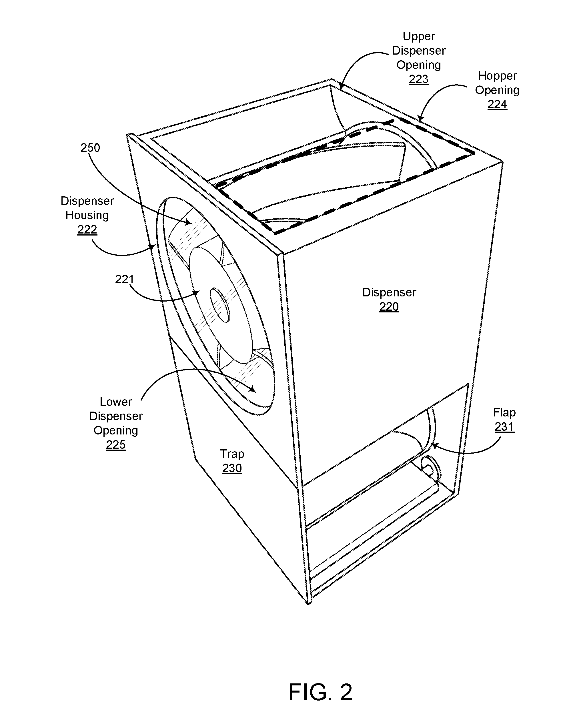
[0021] FIG. 2 illustrates another view of a dispenser unit 220 coupled to a trap unit 230 according to another embodiment. This view illustrates the rotational nature of a dispenser element 221 and its configuration within the dispenser housing 222 of the dispenser unit 220. Hopper opening 224 is aligned with an upper opening 223 of dispenser 220 so that ingredients from the hopper may move into the channels created between the dispenser element 221 and dispenser housing 222. As described in more detail below, the dispenser element 221 is rotated (e.g., by a motor controlled by a computer) to move a controlled amount of ingredients through the channels and into a lower opening 225 in the dispenser housing 222 and into the trap unit 230. In one embodiment, the lower opening 225 of the dispenser 222 is coupled to an upper opening in the trap 230. The trap 230 includes a flap 231 comprising a hole. As described in more detail below, in a first closed position, the hole may extend horizontally (side-to-side), and a sidewall of the flap 231 forms a barrier between the upper opening of the trap 230 to stop movement of ingredients from dispenser 220, for example. In a second open position, the hole may extend vertically (top-to-bottom) to create passage (or vertical channel) between the upper opening of the trap 230 and a lower opening of trap 230 to allow movement of ingredients from dispenser 220, through the trap 230, and to a physical interface where a receptacle may be positioned to receive the ingredients exiting the trap, for example. In the following Figures and description, it is to be understood that dispenser 220 may or may not include a transparent material 250 (e.g., glass or plastic) to form a window (here, circular) to view the operation of the dispenser element 221, for example.
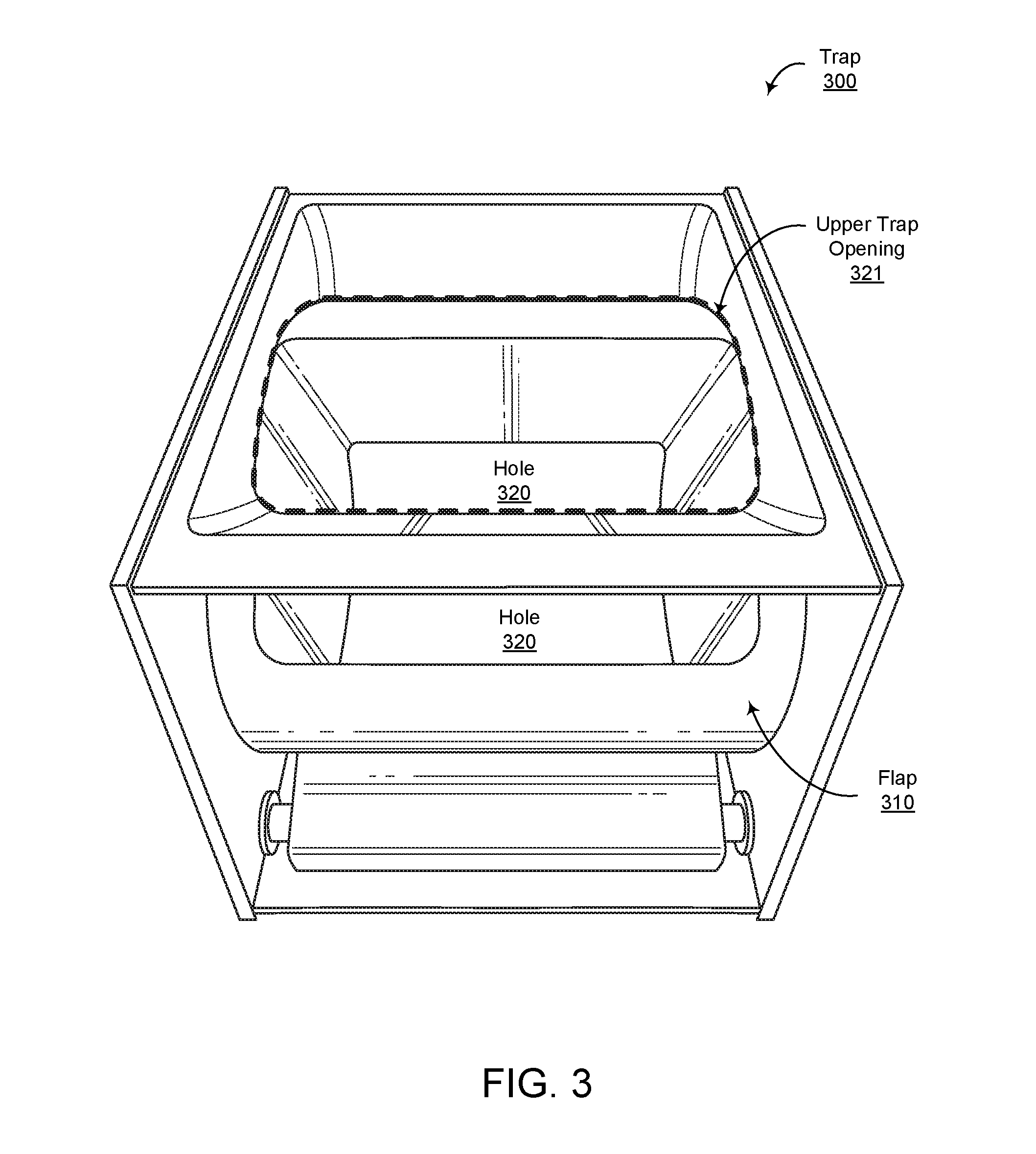
[0022] FIG. 3 illustrates an example trap 300. The trap 300 includes a flap 310 which can be rotated to create a passage (or hole) 320 from an upper opening to a lower opening of the trap. In one example embodiment, the trap is configured below the dispenser element such that when the flap is in a home position, the passage is closed and no amount of the ingredients passes from the dispenser through the trap (the top opening is closed). In this example, the flap is a cylinder having a central hollow region forming a rectangular hole 320. When the flap is in a first position where the rectangular hole is in a horizontal position, the trap is closed, and there is no pathway from an upper opening of the trap to a lower opening of the trap. However, when the flap is in a second position where the rectangular hole is rotated into a vertical position, the trap is open, and there is a pathway from the upper opening of the trap to the lower opening of the trap. In one embodiment, the upper opening 321 in the trap and the lower opening in the trap (not shown) are rectangular and approximately the same size (e.g., aligned in position, size, and cross-sectional shape) as the rectangular hole in the flap to minimize the impedance of ingredients flowing through the trap, for example. In this example, the internal passage of the flap 310 forms a rectangular chamber with rounded edges and the upper and lower trap openings have the same rectangular shape and rounded edges to align with the hole in the flap. In another embodiment, the trap may be integrated with a weighing scale that provides feedback (e.g., to a server or a control unit) about the quantity of product that has been dispensed.
[0023] FIG. 4 illustrates a dispenser unit 400 according to one embodiment. The dispenser unit includes a housing 410 and a dispenser element 420. The dispenser element 420 is coupled about a horizontal axis of rotation 401. The housing 410 has an upper opening 411 coupled to a lower opening 450 of the hopper (not shown) to receive ingredients and a lower opening 412 in which the ingredients exit the dispenser. The dotted line approximately indicates the proximate location of an interface between opening 450, which would be formed by the minor and major inclines at the bottom of the hopper (see FIG. 1), and the upper opening 411 of the dispenser housing. In this example, the upper opening 411 of dispenser 400 has curved sloping surface 430 from an outer opening to an edge forming an inner opening, which intersects with blades 431 of the dispensing element 420 as described below. The blades 431 also intersect with the hopper opening to open and close channels through the dispenser unit from the hopper as described below. A rod may be coupled through the center of the dispenser element 420 and may be coupled to a stepper motor (not shown). The stepper motor may be coupled to a controller (not shown) which may control the rotational position of the dispenser element, which controls the amount of ingredients dispensed as described below.
[0024] FIG. 5 illustrates the dispenser element 500 according to one embodiment. In this example, the dispenser element 500 includes four (4) blades 501-504 which form first and second channels 520 and 521. In this example, the channels are in opposite quadrants on opposite sides of the dispenser element. The 4 blades emanate from a cylindrical base 510 about the horizontal axis 501. The blades 501-504 emanate from the base 510 at a number of degrees (e.g., 90 degrees) from each other at a proximate end 511 of the cylinder 510. Two adjacent blades 501 and 504 of the four blades 501-504 form the first channel 520 and the other two adjacent blades 502 and 503 of the four blades 501-504 form the second channel 521. Ingredients from the hopper may flow from the top down (here, from the right to the left). The dispenser element 500 may be rotated back and forth (e.g., clockwise and then counter clockwise) between first and second degrees (e.g., from 0 to less than 90 degrees and back) to control the flow of items from an upper opening in the dispenser housing through the first and second channels and to a lower opening in the housing (see FIG. 4). As described in more detail below, FIG. 5 illustrates opening 550 formed by the blade 501, a sidewall 551 of the dispenser housing (not shown, but illustrated using a dashed line), and an edge 552 of the lower opening in the hopper (also not shown but illustrated using a dashed line). A similar triangular shaped channel opening may be formed for the second channel 521. As discussed below, the angle of rotation of the dispensing element may increase or decrease the size of channel openings 550 to control the amount of ingredients that flow into each channel and through the dispenser, for example.
[0025] In one embodiment, the first and second channels curve about the horizontal axis such that the first and second channels shift by a number of degrees (e.g., 90 degrees) from the proximate end 511 (e.g., the top in FIG. 5) to the distal end 512 (e.g., the bottom in FIG. 5) of the dispenser element 500.
[0026] In one example embodiment, the hopper incorporates an agitation mechanism that periodically agitates the product in the dispenser without dispensing the product such that the product stays in state that is easy to dispense. The frequency and the agitating mechanisms (e.g., circular motion with different blades, impact force along the back wall, etc. . . . ) may be controlled by a combination of local and cloud servers in concert with the type of product in the hopper, for example.
[0027] FIG. 6 illustrates a dispenser element 500 in a first threshold position in which the leading edge (here, blade 504) of the first channel 520 at the rear (and not visible) is at 0 degrees (relative to angle A). For example, blade 504 of the first channel 520 curves from the horizontal position in the front of the dispenser housing to the vertical position in the rear of the dispenser housing, where blade 504 may form a seal with incline 112 (FIG. 1) at the edge of the opening 590 (opening 111 in FIG. 1) defined by the hopper (See FIG. 8 showing a top view where the upper blade 504 of the first channel 520 is at the edge of the hopper opening 590 and the first channel 520 is closed). Additionally, blade 503 of the second channel 521 curves from the vertical position in the front of the dispenser housing to the horizontal position in the rear of the dispenser housing. Accordingly, blade 503 is also at the edge of the opening 590 defined by the hopper to form an opening 550 (in FIG. 5) into the second channel (See FIG. 8 showing a top view where the upper blade 503 of the second channel 521 is at the edge of the hopper opening 590 and the second channel 521 is fully opened). As the dispensing element is rotated (e.g., first clockwise and then counterclockwise) an input opening into the first channel may increase in size and the opening into the second channel may decrease in size. As ingredients enter each channel they may move through a channel formed by the sidewalls of the blades and the sidewall 600 of the dispenser housing toward the lower opening in the dispenser housing 601.
[0028] FIG. 7 illustrates a dispenser element in a second threshold position in which the leading edge of the second channel 521 (blade 503) at the front (and visible) is at 0 degrees (relative to angle B). Since the upper blade 503 of the second channel 521 is adjacent to the upper opening of the dispensing unit, the second channel is closed in this position (See FIG. 9). More specifically, blade 504 of the first channel 520 curves from the shown position in the front of the dispenser housing to a position in line with the front position of blade 503 (90 degrees) in the rear of the dispenser housing, where blade 504 is at a second edge of the opening 590 defined by the hopper (See FIG. 9 showing a top view where the upper blade 504 of the first channel 520 is at a second edge of the hopper opening 590 and the first channel 520 is fully opened). Note that embodiments of the disclosure may include blades that are long enough to intersect the edge of the hopper incline 112 (FIG. 1) to seal the first channel, for example. Additionally, blade 503 of the second channel 521 curves from shown position in the front of the dispenser housing (zero degrees relative to angle B) to a position in line with the front position of blade 502 (90 degrees) in the rear of the dispenser housing. Accordingly, blade 503 is also at the same edge of the opening 590 as the rear portion of blade 504 (e.g., the edge of the opening 590 defined by the dispenser housing, See FIG. 9 showing a top view where the upper blade 503 of the second channel 521 is at the edge of the hopper opening 590 and the second channel 521 is fully closed). As the dispensing element is rotated (e.g., first counterclockwise and then clockwise) an input opening into the second channel may increase in size and the opening into the first channel may decrease in size.
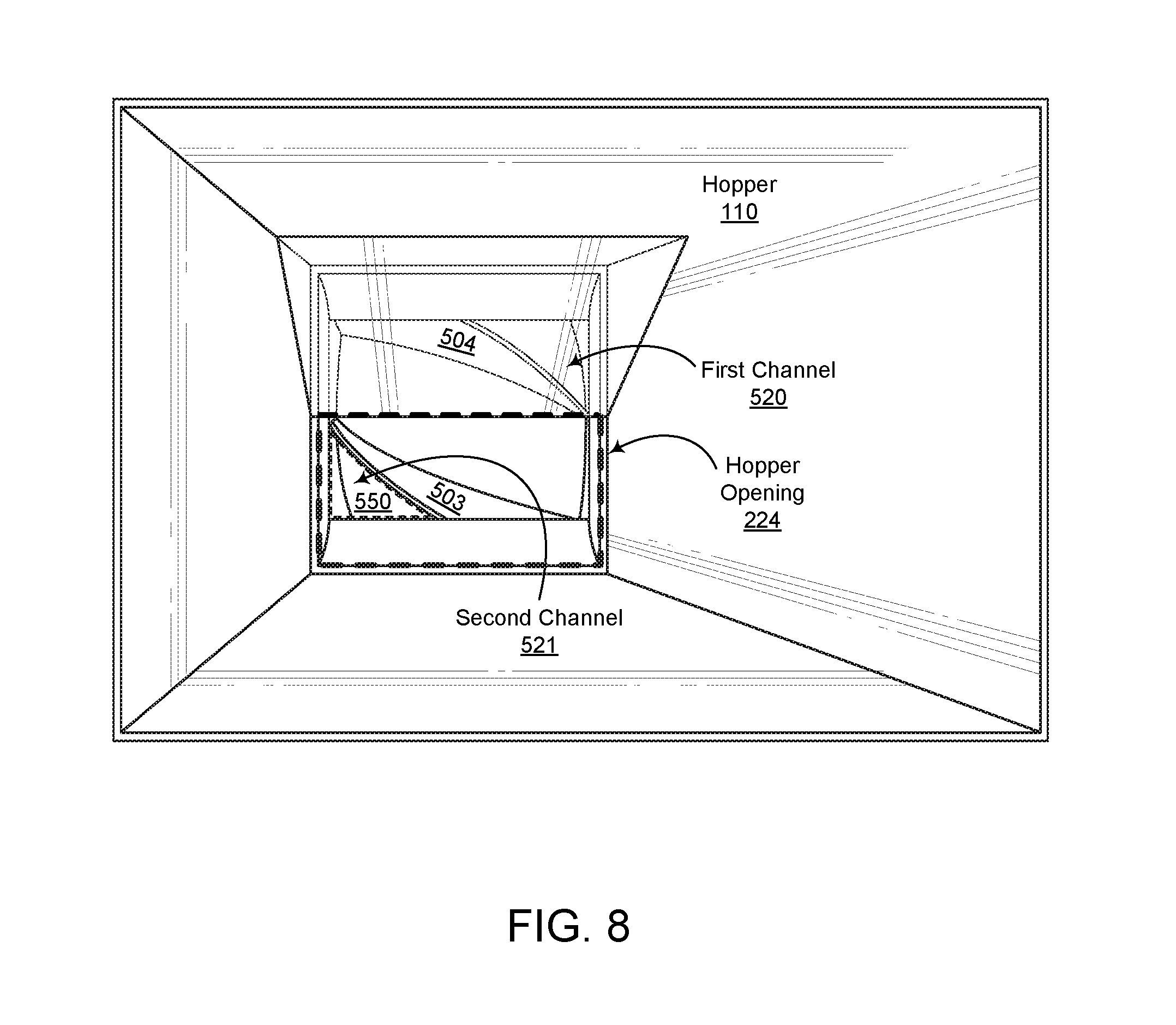
[0029] FIG. 8 illustrates a top view of a dispenser apparatus according to one embodiment. FIG. 8 shows a dispenser unit view through the top of a hopper 110 in the first threshold position shown in FIG. 6. The position of the blade corresponds to FIG. 6, or with reference to FIG. 7 to a configuration where the dispensing element is rotated along angle B approximately 40-45 degrees which creates an opening minor B 550 which would allow ingredients to fall into the second channel 521. In this position, the first channel 520 may be close or have an opening so small that no ingredients may enter, for example. However, the rotation that opens the second channel 521 to the upper opening of the housing (e.g., hopper opening 224) also creates an opening in the first channel to the lower opening of the housing 601 (see FIGS. 6-7), allowing items to flow out of the first channel 520. Additionally, dispensing element 500 may be rotated such that there may be positions in which both the first and second channels have upper openings simultaneously. The size of the opening minor B for the second channel is approximately the same size as the lower opening for the first channel. Accordingly, the size of these openings, as set by the angle of rotation by a motor, for example, may be used to control the amount of items that flow through the channels.
[0030] FIG. 9 illustrates a top view of a dispenser apparatus according to one embodiment. FIG. 9 shows a dispenser unit view through the top of a hopper 110 in the second threshold position shown in FIG. 7. The position of the blade corresponds to FIG. 7, or with reference to FIG. 6 a configuration where the dispensing element is rotated along angle A approximately 40-45 degrees which creates an opening minor A 551 which would allow ingredients to fall into the first channel 520 but not the second channel. Since no ingredients can enter the second channel, flow through the second channel is stopped. Additionally, referring again to FIG. 7, ingredients may enter the first channel but flow is stopped because the sidewalls of the dispensing unit housing extend at least 90 degrees between an upper opening of the housing and a lower opening of the housing. As shown in FIG. 7 the lower blade 501 of the first channel 520 is adjacent to the edge of the housing sidewall 600, thereby forming a seal in the first channel that prevents the flow of items from the upper opening to the lower opening of the dispensing unit. According, given the symmetry of the present example, when either the first or second channels are fully opened at the top of the dispensing unit to receive ingredients, they are also fully closed at the bottom of the dispensing unit to prevent ingredients from exiting the dispenser. Conversely, when either the first or second channels are fully closed at the top of the dispensing unit, they are also fully opened at the bottom of the dispensing unit so that ingredients may exit the dispenser. Similarly, the size of one input opening for one channel is typically the same size as an output opening of the other channel in this example.
[0031] Referring to FIGS. 6-9, the dynamic operation of the dispenser is as follows. Referring to FIG. 6, the first channel 520 may be selectively rotated into a position between 40 and 80 degrees from the first threshold position (e.g., in the direction of angle A) corresponding to a variable opening between the first channel 520 and the opening 590 (See FIG. 9 showing the first channel forming an opening 551 in the dispenser housing and bottom of the hopper). This allows a first amount of the ingredients to enter the first channel. If the angle of rotation is less than 45 degrees (A<45 degrees), for example, based on the configuration of the particular lower opening of the dispenser housing, the dispenser element may be in a position allowing the first amount of ingredients to exit the first channel and fall into the trap. This is illustrated in FIG. 6, for example, where the lower vertical blade 501 of the first channel maintains an opening to the trap up to about 45 degrees, where blade 501 intersects an edge of the lower opening 601 in the dispenser housing and the first channel 520 becomes closed at the bottom.
[0032] Referring to FIG. 7, the second channel 521 may be selectively rotated into a position between 40 and 80 degrees, for example, from the second threshold position (e.g., in the direction of angle B) corresponding to a variable opening between the second channel and the opening in the housing (See FIG. 8 showing the second channel forming an opening 550 in the dispenser housing and bottom of the hopper). This allows a second amount of the ingredients to enter the second channel. If the angle of rotation is less than 45 degrees (B<45 degrees), for example, based on the configuration of the particular dispenser housing lower opening, the dispenser element may be in a position allowing a second amount of ingredients to fall out of the second channel and into the trap.
[0033] In one example embodiment, the first and second channels are selectively rotated into a home position, which may be the position shown in FIG. 7, for example. In the home position, no amount of the ingredients passes through the dispenser unit. In one embodiment, the first and second openings created by moving the dispenser element clockwise and counter clockwise are configured to be the same so that approximately equal portions pass through each channel. The angle of rotation may further control the amount flowing into each channel, for example.
[0034] Advantageously, as mentioned above, the size of the channel inputs may be varied so that the system reliably delivers different amounts of repeatable quantities of ingredients. For example, one or more rotational movements may deliver a first amount of ingredients for a first use, and another one or more rotational movements may deliver a second amount of ingredients for a second use. This is particularly advantageous where the dispenser is used to dispense solid food items for consecutive orders which may use different amounts of ingredients, for example.
[0035] FIG. 10 illustrates another example dispenser element 1000 according to another embodiment. The dispenser element has a first channel 1020. Other embodiments may further include a symmetrical second channel in an opposite quadrant on the opposing side of the first channel. In one embodiment, the first, or first and second, channels may operate similar to the dispenser element of FIG. 5. However, different shapes of first and second channels may be machined or molded such that the ingredients are less likely to stick and flow more effectively.
[0036] FIG. 11 illustrates a fully automated computer controlled dispenser system according to an embodiment. This example illustrates a hopper unit 1100 coupled to a dispenser unit 1101, coupled to a trap unit 1102. Ingredients in the hopper move into the dispenser unit and through the trap as described above. The dispenser element in the dispenser unit may be controlled by a motor 1111 and a flap in trap unit 1102 may be controlled by a motor 1102, for example. Motors 1111 and 1112 are coupled to a controller 1110, which receives instructions from a server (e.g., local server 1130). Instructions from server 1130 may include an amount of ingredients to dispense, for example, which may have been received as part of are recipe from cloud server 1140, for example. The amount may be converted into a particular number of back and forth movements of the motor 1111 to move a dispenser element to dispense the amount in the instruction. In this example, a receptacle 1103 is placed (e.g., by a robotic arm) in a physical interface 1104 to receive ingredients that flow through the dispenser and through the trap. The receptacle 1103 may be placed on a scale 1105 to measure the weight of ingredients dispensed. Scale 1105 sends the weight of the dispensed ingredients to controller 1110 to form a feedback loop causing motor 1111 to rotate dispensing element to dispense more ingredients until a desired weight is obtained. In one embodiment, the weight measured on the scale is sent from the controller to the server, and the server continues to issue updated amounts to dispense until a desired weight is obtained, for example. For example, the controller may provide a feedback signal to the server with a weight measured by the scale such that the server responds to the weight of ingredients within the receptacle to configure the controller to dispense an updated weight of ingredients (e.g., a final weight less the weight measured by the scale). Motor 1112 may rotate the flap to configure trap 1102 in the open position at the beginning of a dispense operation, for example, and may configure trap 1102 in the closed position after a desired weight is obtained. For example, in response to a command from the server to the controller to dispense, the controller configures the motor to open the trap, and the controller closes the trap prior to responding to the server that the dispense operation is completed. Finally, this example illustrates the use of an agitator 1113 coupled to controller 1110. Agitator 1113 may include an electrical vibrator activated by controller 1110 to create vibrations in the hopper 1110 so that ingredients do not stick to the sidewalls or inclines of the hopper, for example.
[0037] Referring again to FIG. 7, in one embodiment, a second position a rotational difference from the home position (shown in FIG. 7) may be determined by a predetermined calibration factor corresponding to at least a size of the first channel, a desired amount of the ingredients, and/or a cut size of the ingredients, for example. This calibration factor may also include other positions as well. The calibration factor may comprise different values downloaded from a cloud server over the internet based on different ingredients of different sizes, for example. For instance, ingredients may be pineapple which has a chef's cut. Fruit of this cut may have been empirically characterized at the factory and a table of values may be ready for sending to each dispenser apparatus. In one embodiment, an initial calibration factor is loaded from the server to the controller to set a rotation value (e.g., amount of rotation for a given amount of a particular ingredient) and a cycle value (e.g., number of back and forth cycle) to deliver the desired weight of the items.
[0038] Additionally, different cut sizes of different ingredients may have different size dispenser elements. For example, a larger cut size may have a cylindrical base with a smaller radius and blades with correspondingly larger heights, where another smaller cut size may have a cylindrical base with a larger radius and blades with correspondingly smaller heights. Accordingly, in one embodiment, for a first size of items, the cylinder has a first diameter and the blades have a first radial length. In another embodiment, for a second size of items greater than the first size of items, the cylinder has a second diameter and the blades have a second radial length. The first diameter is greater than the second diameter and the first radial length is less than the second radial length.
[0039] In one embodiment, the dispenser element agitates (rotates back and forth) between two predefined positions to provide first and second amounts of ingredients. The two positions may be symmetrical because, as mentioned above, the input opening size of one channel at the upper opening may correspond to an output opening size of the other channel at the lower opening. This allows for alternating first and second channel dispensing of ingredients in succession. This may provide for nearly equal quantized portions of the ingredient to be dispensed from each channel into the lower opening of the dispenser unit and through the trap, for example.
[0040] In yet another embodiment the first amount of an ingredient is an incremental amount, and the dispenser element agitates between the two positions through a predetermine number of cycles to provide a final amount of the ingredient.
[0041] In one embodiment, the dispenser apparatus includes a scale to measure the weight of the first amount of ingredients after falling out of the first channel. In one embodiment, a receptacle is situated to receive the items exiting the trap and a scale is situated to measure the weight of the receptacle and items located within the receptacle. In another embodiment, the value of weight is used to control the motor coupled to the dispensing element to dispense a final amount of the ingredients specified in an instruction received from the local server, for example.
[0042] In yet another embodiment, a controller is coupled to control a motor (e.g., a stepper motor) coupled to open and close the trap, and a server is coupled to the controller. In response to an instruction from the server to the controller to dispense, for example, the controller opens the trap, and the controller closes the trap prior to responding to the server that the dispense operation is completed.
[0043] In one embodiment, the scale provides a feedback signal to the controller such that the dispenser element responds to the weight of items within the receptacle in a local feedback loop to deliver a desired weight of the items. In another embodiment, a feedback loop between the dispenser and the local server may fine tune the weight of items in the receptacle.
[0044] In another embodiment, the dispenser apparatus includes a server coupled to the controller. An initial calibration factor is loaded from the server to the controller to begin an initial rotation value and cycle value to deliver the desired weight of the items.
[0045] The above description illustrates various embodiments of the present disclosure along with examples of how aspects of the particular embodiments may be implemented. The above examples should not be deemed to be the only embodiments, and are presented to illustrate the flexibility and advantages of the particular embodiments as defined by the following claims. Based on the above disclosure and the following claims, other arrangements, embodiments, implementations and equivalents may be employed without departing from the scope of the present disclosure as defined by the claims.
* * * * *
D00000
D00001
D00002
D00003
D00004
D00005
D00006
D00007
D00008
D00009
D00010
D00011
XML
uspto.report is an independent third-party trademark research tool that is not affiliated, endorsed, or sponsored by the United States Patent and Trademark Office (USPTO) or any other governmental organization. The information provided by uspto.report is based on publicly available data at the time of writing and is intended for informational purposes only.
While we strive to provide accurate and up-to-date information, we do not guarantee the accuracy, completeness, reliability, or suitability of the information displayed on this site. The use of this site is at your own risk. Any reliance you place on such information is therefore strictly at your own risk.
All official trademark data, including owner information, should be verified by visiting the official USPTO website at www.uspto.gov. This site is not intended to replace professional legal advice and should not be used as a substitute for consulting with a legal professional who is knowledgeable about trademark law.