Upper Cover Assembly, Atomizing Device And Electronic Cigarette Thereof
QIU; Weihua
U.S. patent application number 16/448570 was filed with the patent office on 2019-10-10 for upper cover assembly, atomizing device and electronic cigarette thereof. The applicant listed for this patent is Changzhou Patent Electronic Technology Co., LTD. Invention is credited to Weihua QIU.
| Application Number | 20190307173 16/448570 |
| Document ID | / |
| Family ID | 59586733 |
| Filed Date | 2019-10-10 |


View All Diagrams
| United States Patent Application | 20190307173 |
| Kind Code | A1 |
| QIU; Weihua | October 10, 2019 |
UPPER COVER ASSEMBLY, ATOMIZING DEVICE AND ELECTRONIC CIGARETTE THEREOF
Abstract
An upper cover assembly includes an upper cover and a liquid injecting cover movable relative to the upper cover between locked position and unlocked position, the upper cover is provided with a liquid injecting port; when the liquid injecting cover is in the locking position relative to the upper cover, the liquid injecting cover is covered on the upper cover and cannot be turned over relative to the upper cover, the liquid injecting port is closed; when the liquid injecting cover is moved from the locking position to the unlocking position with respect to the upper cover by an external force, the liquid injecting cover can be turned over and opened with respect to the upper cover to expose the liquid injecting port. When the liquid injecting cover is in the locked position, the liquid injection cover is in communication with the smoke outlet, the electronic cigarette can be normally used for smoking; when the liquid injecting cover is translated from the locked position to the unlocked position, it is turned over and opened, the liquid injecting port is exposed, the electronic cigarette can be injected. An atomizing device and an electronic cigarette with the upper cover assembly are also provided.
| Inventors: | QIU; Weihua; (Changzhou, CN) | ||||||||||
| Applicant: |
|
||||||||||
|---|---|---|---|---|---|---|---|---|---|---|---|
| Family ID: | 59586733 | ||||||||||
| Appl. No.: | 16/448570 | ||||||||||
| Filed: | June 21, 2019 |
Related U.S. Patent Documents
| Application Number | Filing Date | Patent Number | ||
|---|---|---|---|---|
| PCT/CN2017/087007 | Jun 2, 2017 | |||
| 16448570 | ||||
| Current U.S. Class: | 1/1 |
| Current CPC Class: | A24F 47/00 20130101; A61M 2209/045 20130101; A24F 47/008 20130101; A24F 9/16 20130101 |
| International Class: | A24F 47/00 20060101 A24F047/00; A24F 9/16 20060101 A24F009/16 |
Foreign Application Data
| Date | Code | Application Number |
|---|---|---|
| Dec 21, 2016 | CN | 201621406359.X |
Claims
1. An upper cover assembly, comprising: an upper cover, the upper cover is provided with a liquid injecting port; and a liquid injecting cover movable relative to the upper cover between locked position and unlocked position; when the liquid injecting cover is in the locking position relative to the upper cover, the liquid injecting cover is covered on the upper cover and cannot be turned over relative to the upper cover, the liquid injecting port is closed; when the liquid injecting cover is moved from the locking position to the unlocking position with respect to the upper cover by an external force, the liquid injecting cover can be turned over and opened with respect to the upper cover to expose the liquid injecting port.
2. The upper cover assembly of claim 1, wherein the upper cover is provided with a translating groove for the liquid injecting cover to move between the locking position and the unlocking position, the liquid injecting cover is provided with a rotating shaft, the rotating shaft is movable along with the translation slot, the liquid injecting cover is rotatable relative to the upper cover about the rotating shaft.
3. The upper cover assembly of claim 2, wherein the upper cover comprises a bottom cover and a gland disposed on the bottom cover, the liquid inlet is disposed on the bottom cover, an edge of one side of the gland is recessed inwardly to form a notch having an opening at one end, the liquid inlet is received in the notch and exposed through the notch.
4. The upper cover assembly of claim 3, wherein the notch comprises a connecting wall located at a side of the smoke outlet away from the liquid injecting port and two side walls connected to opposite ends of the connecting wall and extending in the same direction, the surface of the connecting wall near the bottom cover is further recessed to form a recess in a direction away from the smoke outlet, the surface of the two side walls connected to the connecting wall is recessed in a direction away from the bottom cover to form a translating groove, the translating groove is in communication with the notch and the recess; when in the locked position, one end of the liquid injecting cover is received and limited to be located in the groove; when the liquid injecting cover is moved from the locked position to the unlocked position, the liquid injecting cover is moved out of the groove along the translation groove and can be turned over.
5. The upper cover assembly of claim 4, wherein the liquid injecting cover comprises a cover body capable of closing the liquid injecting cover when the liquid injecting cover is in the locking position, the rotating shaft is disposed at two opposite sides of one end of the cover body.
6. The upper cover assembly of claim 5, wherein the liquid injecting cover comprises a covering portion disposed on the other end of the cover body opposite to the rotating shaft, the covering portion extends to both sides with respect to the cover body and has a width in the circumferential direction of the gland greater than the width of the notch, the bottom of the gland on both sides of the notch is provided with a locking groove in communication with the notch, the width of the locking groove in the circumferential direction of the gland is larger than the width of the notch, when the liquid injecting cover is in the locking position, the covering portion is received in the locking groove and resists the groove wall of the locking groove; when the liquid injecting cover is in the unlocking position, the covering portion can be removed out of the locking groove, the liquid injecting cover can be turned over relative to the upper cover.
7. The upper cover assembly of claim 2, wherein the upper cover is further provided with a smoke outlet, the smoke outlet and the liquid injecting port are sequentially disposed on the upper cover in a direction in which the locking position is directed to the unlocking position, the liquid injecting cover is provided with a through hole, the through hole is in communication with the smoke outlet when the liquid injecting cover is in the locked position with respect to the upper cover.
8. The upper cover assembly of claim 1, wherein the upper cover comprises a first connecting portion that can restrict the liquid injecting cover from being turned over when the liquid injecting cover is in the locking position, the liquid injecting cover is provided with a second connecting portion that can be locked or unlocked with the first connecting portion.
9. The upper cover assembly of claim 2, wherein the upper cover comprises a bottom cover and a gland, the bottom cover is provided with a locking groove, the stopping member is locked in the locking groove, the opposite side walls of the limiting groove along the length direction of the stopping member are concavely defined with a translating groove.
10. The upper cover assembly of claim 9, wherein the liquid injecting cover comprises a locking member, when the liquid injecting cover is in the locking position, the liquid injecting port can be sealed by the locking member, the rotating shaft is disposed on the locking member, the rotating shaft is movable along the translating groove to be locked with the stopping member.
11. The upper cover assembly of claim 10, wherein the surface of the stopping member facing away from the liquid injecting cover is defined with an corresponding groove, the stopping member is provided with a limiting groove at one end away from the socket, one end of the locking member is provided with a claw slidably disposed in the corresponding groove, the locking member is provided with a limiting member slidably disposed in the limiting groove, the limiting groove is located at one end of the locking member relative to the claw, the rotating shaft is disposed on the limiting member.
12. The upper cover assembly of claim 11, wherein a surface of the stopper facing the liquid injecting cover is provided with a socket that is in communicates with the corresponding groove, the claw is movable in the corresponding groove after passing through the socket, a locking groove is provided at the claw, the corresponding groove is provided with a projection therein corresponding to the locking groove; when the liquid injecting cover is in the locking position, the projection is locked in the locking groove, the periphery of the socket abuts against the claw.
13. The upper cover assembly of claim 8, wherein the first connecting portion and the second connecting portion are provided with a magnetic member, respectively; the first connecting portion is magnetically connected to the second connecting portion when the liquid injecting cover is in the locking position.
14. The upper cover assembly of claim 11, wherein the upper cover further comprises an elastic member, the elastic member comprises a clamping portion and a resisting portion connected to the clamping portion, The resisting portion is connected to a side of the clamping portion away from the socket, one end of the resisting portion away from the clamping portion is inclined away from the bottom wall of the locking groove; when the liquid injecting cover moves between the locking position and the unlocking position, the resisting portion always abuts against the limiting member.
15. The upper cover assembly of claim 10, wherein the upper cover further comprises an upper covering case sleeved on the bottom cover, the liquid injecting cover further comprises a cover body connected to one end of the locking member away from the upper cover, the upper cover is provided with a smoke outlet, the cover body is provided with a through hole, the through hole is in communication with the smoke outlet when the liquid injecting cover is in the locked position with respect to the upper cover.
16. An atomizing device, comprising: an upper cover assembly, comprises an upper cover and a liquid injecting cover movable relative to the upper cover between locked position and unlocked position; the upper cover is provided with a liquid injecting port; when the liquid injecting cover is in the locking position relative to the upper cover, the liquid injecting cover is covered on the upper cover and cannot be turned over relative to the upper cover, the liquid injecting port is closed; when the liquid injecting cover is moved from the locking position to the unlocking position with respect to the upper cover by an external force, the liquid injecting cover can be turned over and opened with respect to the upper cover to expose the liquid injecting port.
17. The atomizing device of claim 16, wherein the atomizing device comprises a base assembly, a liquid storage tube and an atomizing core assembly, the liquid storage tube is sleeved on the base assembly, the liquid storage tube and the base assembly form a liquid storage chamber, the atomizing core assembly is received in the liquid storage chamber, the upper cover assembly is disposed at one end of the liquid storage tube opposite to the base assembly, and is in communication with the liquid storage chamber through the liquid injecting port.
18. An electronic cigarette, comprising: an atomizing device comprises an upper cover assembly, the upper cover assembly comprises an upper cover and a liquid injecting cover movable relative to the upper cover between locked position and unlocked position; the upper cover is provided with a liquid injecting port; when the liquid injecting cover is in the locking position relative to the upper cover, the liquid injecting cover is covered on the upper cover and cannot be turned over relative to the upper cover, the liquid injecting port is closed; when the liquid injecting cover is moved from the locking position to the unlocking position with respect to the upper cover by an external force, the liquid injecting cover can be turned over and opened with respect to the upper cover to expose the liquid injecting port.
19. The electronic cigarette of claim 18, wherein the atomizing device comprises a base assembly, a liquid storage tube and an atomizing core assembly, the liquid storage tube is sleeved on the base assembly, the liquid storage tube and the base assembly form a liquid storage chamber, the atomizing core assembly is received in the liquid storage chamber, the upper cover assembly is disposed at one end of the liquid storage tube opposite to the base assembly, and is in communication with the liquid storage chamber through the liquid injecting port.
20. The electronic cigarette of claim 18, wherein the upper cover is provided with a translating groove for the liquid injecting cover to move between the locking position and the unlocking position, the liquid injecting cover is provided with a rotating shaft, the rotating shaft is movable along with the translation slot, the liquid injecting cover is rotatable relative to the upper cover about the rotating shaft.
Description
CROSS-REFERENCE TO RELATED APPLICATIONS
[0001] The present application is a continuation-in-part of international application No. PCT/CN2017/087007 filed on Jun. 2, 2017, and claims priority to Chinese patent application No. 201621406359.X filed on Dec. 21, 2016, and the entire disclosures of the foregoing applications are incorporated herein by reference.
FIELD
[0002] The present invention relates to an electronic cigarette, in particular to an upper cover assembly, an atomizing device, and electronic cigarette.
BACKGROUND
[0003] The atomizing device of the traditional electronic cigarette needs to be unscrewed when the liquid is injected, which is inconvenient to inject. And the process of disassembling the upper cover or the base is cumbersome. In addition, when the liquid is screwed to the upper cover of the atomizing device, the pressure in the atomizing device cavity is easily changed to cause liquid leakage, which causes great inconvenience to the user. While children are also easily accessible to e-cigarette liquid, there are security risks.
SUMMARY
[0004] The present disclosure provides an upper cover assembly that facilitates liquid injection and does not cause pressure changes in the chamber of the atomization device when the liquid injection cover is opened.
[0005] Further to provide an atomizing device having the upper cover assembly.
[0006] More further to provide a cigarette having the atomizing device.
[0007] An upper cover assembly includes an upper cover and a liquid injecting cover that can move between locking position and unlocking position relative to the upper cover between, the upper cover is provided with a liquid injecting port, when the liquid injecting cover is in the locking position relative to the upper cover, the liquid injecting cover is covered on the upper cover and cannot be rotated relative to the upper cover, the liquid injecting port is closed; when the liquid injecting cover is moved from the locking position to the unlocking position with respect to the upper cover by an external force, the liquid injecting cover can be turned over and opened with respect to the upper cover to expose the liquid injecting port.
[0008] In one embodiment, the upper cover is provided with a translating groove for the liquid injecting cover to move between the locking position and the unlocking position, the liquid injecting cover is provided with a rotating shaft, the rotating shaft is movable along with the translation slot, the liquid injecting cover is rotatable relative to the upper cover about the rotating shaft.
[0009] In one embodiment, the upper cover includes a bottom cover and a gland disposed on the bottom cover, the liquid inlet is disposed on the bottom cover, an edge of one side of the gland is recessed inwardly to form a notch having an opening at one end, the liquid inlet is received in the notch and exposed through the notch.
[0010] In one embodiment, the notch includes a connecting wall located at a side of the smoke outlet away from the liquid injecting port and two side walls connected to opposite ends of the connecting wall and extending in the same direction, the surface of the connecting wall near the bottom cover is further recessed to form a recess in a direction away from the smoke outlet, the surface of the two side walls connected to the connecting wall is recessed in a direction away from the bottom cover to form a translating groove, the translating groove is in communication with the notch and the recess; when in the locked position, one end of the liquid injecting cover is received and limited to be located in the groove; when the liquid injecting cover is moved from the locked position to the unlocked position, the liquid injecting cover is moved out of the groove along the translation groove and can be turned over.
[0011] In one embodiment, the liquid injecting cover includes a cover body capable of closing the liquid injecting cover when the liquid injecting cover is in the locking position, the rotating shaft is disposed at two opposite sides of one end of the cover body.
[0012] In one embodiment, the liquid injecting cover includes a covering portion disposed on the other end of the cover body opposite to the rotating shaft, the covering portion extends to both sides with respect to the cover body and has a width in the circumferential direction of the gland greater than the width of the notch, the bottom of the gland on both sides of the notch is provided with a locking groove in communication with the notch, the width of the locking groove in the circumferential direction of the gland is larger than the width of the notch, when the liquid injecting cover is in the locking position, the covering portion is received in the locking groove and resists the groove wall of the locking groove; when the liquid injecting cover is in the unlocking position, the covering portion can be removed out of the locking groove, the liquid injecting cover can be turned over relative to the upper cover.
[0013] In one embodiment, the upper cover is further provided with a smoke outlet, the smoke outlet and the liquid injecting port are sequentially disposed on the upper cover in a direction in which the locking position is directed to the unlocking position, the liquid injecting cover is provided with a through hole, the through hole is in communication with the smoke outlet when the liquid injecting cover is in the locked position with respect to the upper cover.
[0014] In one embodiment, the upper cover includes a first connecting portion that can restrict the liquid injecting cover from being turned over when the liquid injecting cover is in the locking position, the liquid injecting cover is provided with a second connecting portion that can be locked or unlocked with the first connecting portion.
[0015] In one embodiment, the upper cover includes a bottom cover and a gland, the bottom cover is provided with a locking groove, the stopping member is locked in the locking groove, the opposite side walls of the limiting groove along the length direction of the stopping member are concavely defined with a translating groove.
[0016] In one embodiment, the liquid injecting cover includes a locking member, when the liquid injecting cover is in the locking position, the liquid injecting port can be sealed by the locking member, the rotating shaft is disposed on the locking member, the rotating shaft is movable along the translating groove to be locked with the stopping member.
[0017] In one embodiment, the surface of the stopping member facing away from the liquid injecting cover is defined with an corresponding groove, the stopping member is provided with a limiting groove at one end away from the socket, one end of the locking member is provided with a claw slidably disposed in the corresponding groove, the locking member is provided with a limiting member slidably disposed in the limiting groove, the limiting groove is located at one end of the locking member relative to the claw, the rotating shaft is disposed on the limiting member.
[0018] In one embodiment, a surface of the stopper facing the liquid injecting cover is provided with a socket that is in communicates with the corresponding groove, the claw is movable in the corresponding groove after passing through the socket, a locking groove is provided at the claw, the corresponding groove is provided with a projection therein corresponding to the locking groove; when the liquid injecting cover is in the locking position, the projection is locked in the locking groove, the periphery of the socket abuts against the claw.
[0019] In one embodiment, the first connecting portion and the second connecting portion are provided with a magnetic member, respectively; the first connecting portion is magnetically connected to the second connecting portion when the liquid injecting cover is in the locking position.
[0020] In one embodiment, the upper cover further includes an elastic member, the elastic member includes a clamping portion and a resisting portion connected to the clamping portion, The resisting portion is connected to a side of the clamping portion away from the socket, one end of the resisting portion away from the clamping portion is inclined away from the bottom wall of the locking groove; when the liquid injecting cover moves between the locking position and the unlocking position, the resisting portion always abuts against the limiting member.
[0021] In one embodiment, the upper cover further includes an upper covering case sleeved on the bottom cover, the liquid injecting cover further includes a cover body connected to one end of the locking member away from the upper cover, the upper cover is provided with a smoke outlet, the cover body is provided with a through hole, the through hole is in communication with the smoke outlet when the liquid injecting cover is in the locked position with respect to the upper cover.
[0022] An atomizing device includes of any of the above upper cover assemblies.
[0023] In one embodiment, the atomizing device includes a base assembly, a liquid storage tube and an atomizing core assembly, the liquid storage tube is sleeved on the base assembly, the liquid storage tube and the base assembly form a liquid storage chamber, the atomizing core assembly is received in the liquid storage chamber, the upper cover assembly is disposed at one end of the liquid storage tube opposite to the base assembly, and is in communication with the liquid storage chamber through the liquid injecting port.
[0024] An electronic cigarette includes of any of the above atomizing devices.
[0025] The beneficial effects of the present disclosure are:
[0026] For the electronic cigarette of the present disclosure, when the liquid injecting cover is in the locking position, the liquid injecting port is sealed. When the remaining amount of the e-cigarette liquid in the electronic cigarette is insufficient, the liquid injecting cover can be translated from the locking position to the unlocking position, and then turned over to expose the liquid injection port to realize the liquid injection operation. During the operation, the liquid injecting cover can be turned over after being pushed out relative to the upper cover, and cannot be directly turned over. While directly pushing laterally the liquid injecting cover, the covering portion is still covering the liquid injecting port, that is, the separate turning over or pushing laterally will not expose the liquid injecting port, the infusion port must be opened by a two-step operation with a push in the lateral direction and a turning over, so it has child protection.
BRIEF DESCRIPTION OF THE DRAWINGS
[0027] FIG. 1 is a schematic structural view of an atomizing device according to a first embodiment of the present disclosure; (the liquid injecting cover is in the flip state)
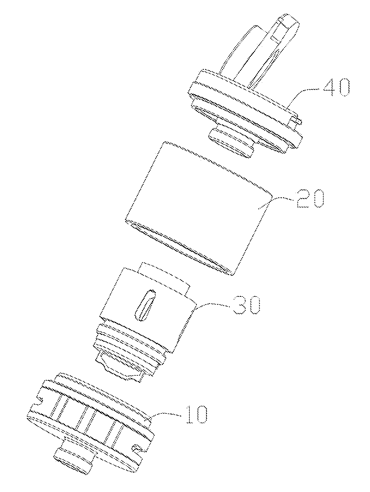
[0028] FIG. 2 is an exploded perspective view of the atomizing device of FIG. 1;
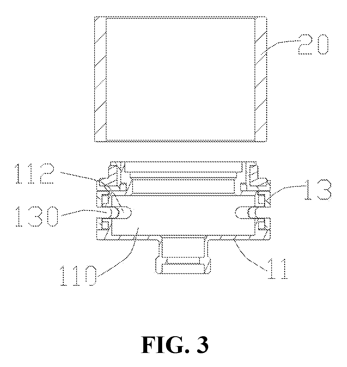
[0029] FIG. 3 is a schematic view showing the structure of the base and the liquid storage tube in the atomizing device shown in FIG. 1;
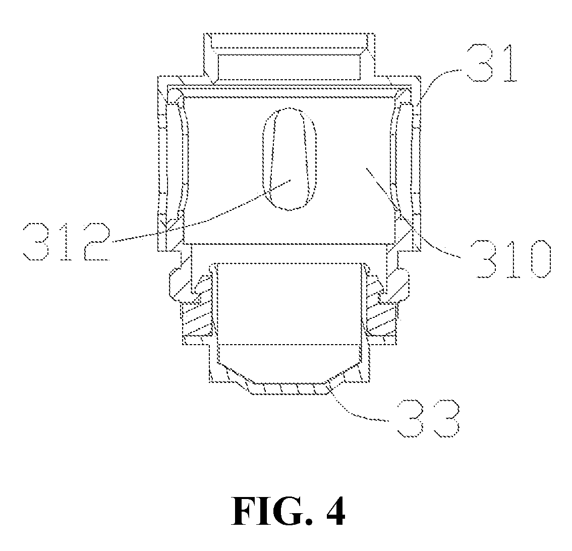
[0030] FIG. 4 is a schematic structural view of an atomizing core assembly in the atomizing device shown in FIG. 1;
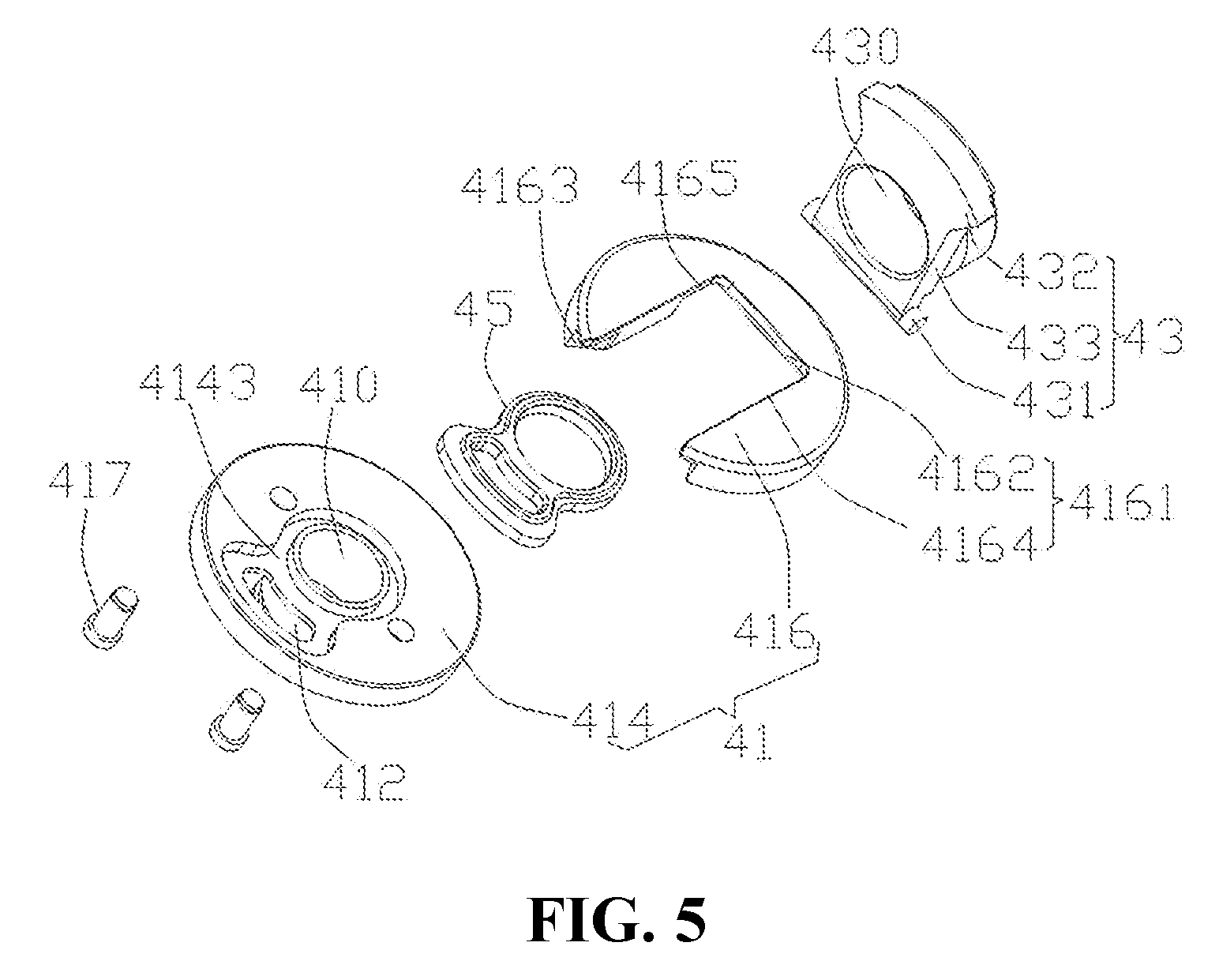
[0031] FIG. 5 is an exploded perspective view of the upper cover assembly of the atomizing device of FIG. 1;
[0032] FIG. 6 is a cross-sectional view of the upper cover assembly of the atomizing device of FIG. 5;
[0033] FIG. 7 is a cross-sectional view of the atomizing device of FIG. 1;
[0034] FIG. 8 is a schematic structural view of an atomizing device according to the second embodiment of the present disclosure; (the liquid injecting cover is in the flip state)
[0035] FIG. 9 is an exploded view of the upper cover assembly of the atomizing device of FIG. 8;
[0036] FIG. 10 is an exploded perspective view of the upper cover assembly of the atomizing device of FIG. 9;
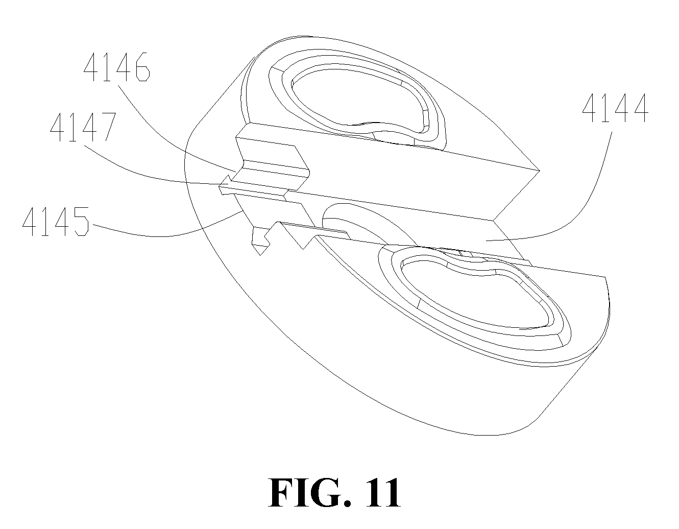
[0037] FIG. 11 is a schematic structural view of a bottom cover of the upper cover assembly of the atomizing device shown in FIG. 8;
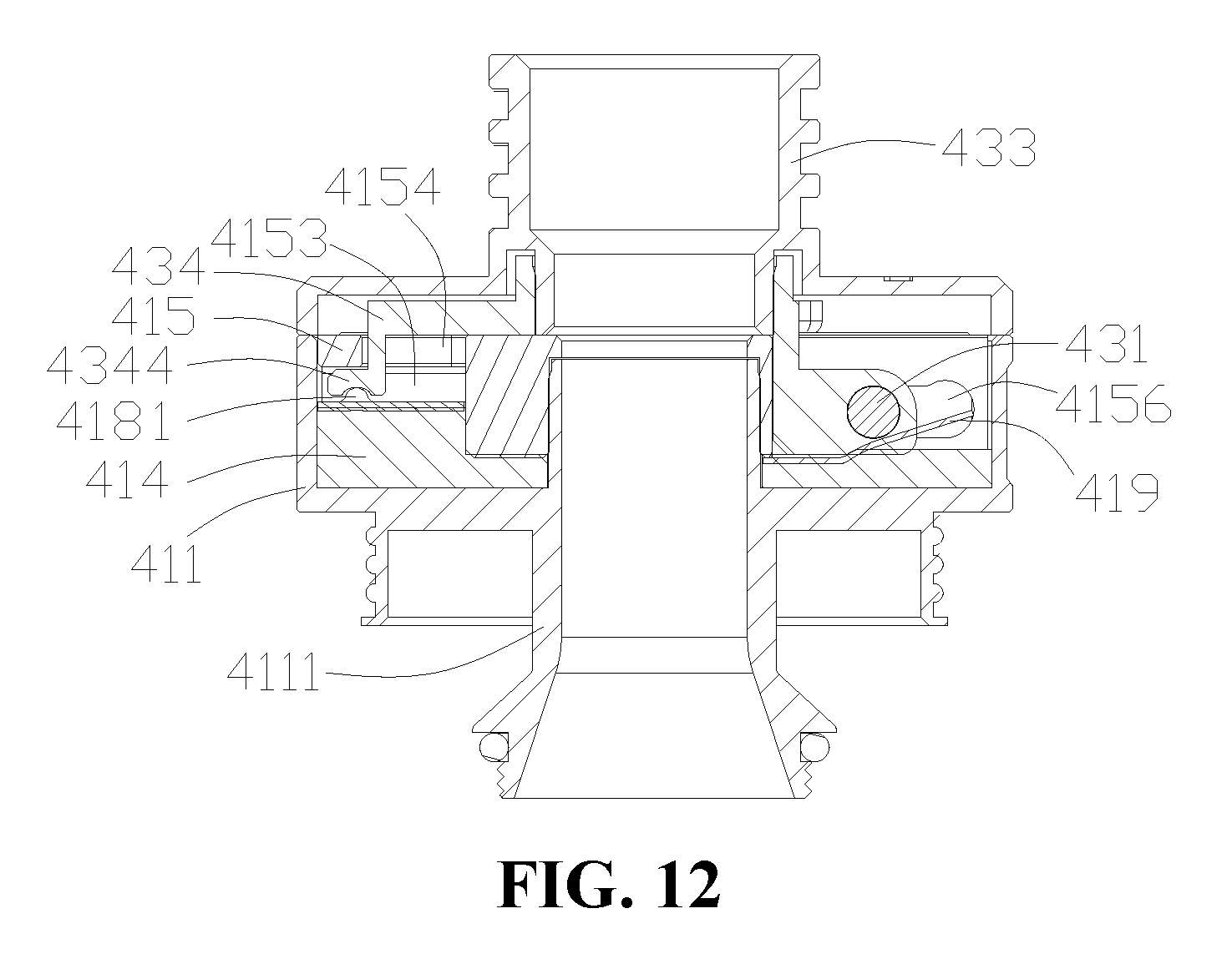
[0038] FIG. 12 is a cross-sectional view of the assembly of the upper cover assembly of the atomizing device of FIG. 8; (the liquid injection cover is in the locked position)
[0039] FIG. 13 is a cross-sectional view showing another state in which the upper cover assembly of the atomizing device shown in FIG. 8 is assembled; (the liquid injecting cover is in the unlocked position)
[0040] FIG. 14 is a cross-sectional view of the atomizing device of FIG. 8.
[0041] The following table list various components and reference numerals thereof.
TABLE-US-00001 Atomization device 100, 200 Base assembly 10 Inner chamber 110 Base 11 Air inlet 112 Air conditioning ring 13 Air conditioning groove 130 Liquid storage tube 20 Liquid storage chamber 21 Atomizing core assembly 30 Atomizing chamber 310 Atomizing tube 31 Electrode contact assembly 33 Liquid inlet hole 312 Upper cover assembly 40 Smoke outlet 410 Liquid injecting port 412 Through hole 430 Bottom cover 414 Connection fixing post 4141, 4111 Sealing ring 418 Sealing groove 4143 Gasket 45 Gland 416 Notch 4161 Connecting wall 4162 Locking groove 4163 Side wall 4164 Recess 4166 Translating groove 4165, 4156 Liquid injecting cover 43 Rotating shaft 431 Cover body 433 Covering portion 432 Pin 417 Upper cover 41 Upper covering case 411 Hole 4142 Locking groove 4144 First boss 4145 Second boss 4146 Notch groove 4147 Pivotal holes 4347 Stopping member 415 Corresponding groove 4151 Cavity 4153 Socket 4154 limiting groove 4155 Limiting member 4346 Fastening member 420 Projection 4181 Elastic member 419 Clamping portion 4191 Resisting portion 4192 Locking member 434 Plug portion 4331 Alignment hole 4341 First connecting member 4342 Claw 4343 Latching groove 4344 Second connecting member 4345 Cigarette holder 50 First connecting portion 422 Second connecting portion 421 Inserting hole 4152
DETAILED DESCRIPTION OF PREFERRED EMBODIMENTS
[0042] It will be appreciated that for simplicity and clarity of illustration, where appropriate, reference numerals have been repeated among the different figures to indicate corresponding or analogous elements. In addition, numerous specific details are set forth in order to provide a thorough understanding of the embodiments described herein. However, it will be understood by those of ordinary skill in the art that the embodiments described herein can be practiced without these specific details. In other instances, methods, procedures and components have not been described in detail so as not to obscure the related relevant feature being described. Also, the description is not to be considered as limiting the scope of the embodiments described herein. The drawings are not necessarily to scale and the proportions of certain parts may be exaggerated to better illustrate details and features of the present disclosure.
[0043] Several definitions that apply throughout this disclosure will now be presented.
[0044] The term "coupled" is defined as connected, whether directly or indirectly through intervening components, and is not necessarily limited to physical connections. The connection can be such that the objects are permanently connected or releasably connected. The term "comprising," when utilized, means "including, but not necessarily limited to"; it specifically indicates open-ended inclusion or membership in the so-described combination, group, series and the like.
[0045] When a feature or element is herein referred to as being "on" another feature or element, it can be directly on the other feature or element or intervening features and/or elements may also be present.
[0046] Terminology used herein is for the purpose of describing particular embodiments only and is not intended to be limiting of the disclosure. As used herein, the term "and/or" includes any and all combinations of one or more of the associated listed items and may be abbreviated as "/".
The First Embodiment
[0047] Referring to FIG. 1 and FIG. 2, in an embodiment of the present disclosure, an electronic cigarette (not shown) includes an atomizing device 100 and a battery device (not shown) for electrically driving the atomizing device 100. The atomizing device 100 includes a base assembly 10, a liquid storage tube 20, an atomizing core assembly 30 with an atomizing chamber 310 (FIG. 7), an upper cover assembly 40 and a mouthpiece (not shown). The liquid storage tube 20 is sleeved on the base assembly 10, the liquid storage tube 20 and the base assembly 10 form a liquid storage chamber 21 for storing the e-cigarette liquid (as shown in FIG. 7). The atomizing core assembly 30 is received in the liquid storage chamber 21 for atomizing e-cigarette liquid. The upper cover assembly 40 is disposed at one end of the liquid storage tube 20 opposite to the base assembly 10, and is selectively in communication with the atomizing chamber 310 and the liquid storage chamber 21, so as to facilitate the user to inhale the smoke formed after the atomization. When the upper cover assembly 40 is in airflow communication with the atomizing chamber 310. When the upper cover assembly is in airflow communication with the liquid storage chamber 21, the air pressure in the liquid storage chamber 21 can be kept stable, the liquid leakage is prevented, and it's convenient for the user to fill the e-cigarette liquid. The mouthpiece is detachably disposed on the upper cover assembly 40 for the user to inhale the smoke formed after the atomization.
[0048] Referring to FIG. 3, specifically, the base assembly 10 is substantially hollow cylindrical, the base assembly 10 includes a base 11 with an inner chamber 110 and an air conditioning ring 13. The base 11 has a substantially hollow cylindrical shape, an air inlet 112 communicating with the inner chamber 110 is defined in a circumferential wall of the base 11. The air distribution ring 13 is circumferentially rotatably sleeved on the outer circumference of the base 11 and has an air conditioning groove 130 in communication with the outside, the air conditioning groove 130 can be in communication with or staggered from the air inlet 112. When the air distribution ring 13 is rotated, the communication area between the air conditioning groove 130 and the air inlet 112 can be adjusted, so that the user can adjust the amount of the air intake as needed.
[0049] The liquid storage tube 20 is a hollow sleeve, two ends of the liquid storage tube 20 are throughout. Optionally, the liquid storage tube 20 is a glass tube or a stainless steel tube, which is sleeved outside the base 11, the liquid storage tube 20 and the base 11 together form a liquid storage chamber 21 for storing e-cigarette liquid.
[0050] Referring to FIG. 4, the atomizing core assembly 30 is received in the liquid storage chamber 21. The atomizing core assembly 30 includes an atomizing tube 31, a heat generating member (not shown), a liquid guiding member (not shown) and an electrode contact assembly 33. The atomizing tube 31 has openings at the upper and lower ends, an atomizing chamber 310 is formed in the atomizing tube 31. The atomizing tube 31 is provided with a liquid inlet hole 312 communicating between the atomizing chamber 310 and the liquid storage chamber 21. The heat generating member and the liquid guiding member are disposed in the atomizing tube 31 for sucking the e-cigarette liquid in the liquid storage chamber 21 and heating and atomizing the e-cigarette liquid using the electric power from the battery device. The heating element can be a heating wire, the liquid guiding piece can be a liquid guiding cotton; the arrangement of the two can be that the liquid guiding cotton is wrapped around the heating wire, or the heating wire is wound around the liquid guiding member. The electrode contact assembly 33 is disposed at the bottom of the atomizing tube 31, one end is electrically connected to the heat generating member, the other end is electrically connected to the battery device to provide electrical power to the atomizing core assembly 30.
[0051] The external air enters the inner chamber 110 of the base 11 from the air conditioning groove 130 of the air distribution ring 13 and the air inlet 112 of the base 11, and then enters the atomizing chamber 310 from the lower end of the atomizing tube 31. The e-cigarette liquid in the atomizing chamber 310 is atomized to form smoke, the external air and the smoke pass through the top of the atomizing tube 31 and the upper cover assembly 40, and then flow into the mouthpiece for the user to inhale.
[0052] Referring to FIGS. 5 and 6, the upper cover assembly 40 includes an upper cover 41 and a liquid injecting cover 43 that can move relative to the upper cover 41 between the locking position and the unlocking position. The upper cover 41 is sequentially provided with a smoke outlet 410 and a liquid injecting port 412 along the movement path of the liquid injecting cover 43 from the locking position to the unlocking position, the liquid injecting cover 43 is provided with a through hole 430. When the liquid injecting cover 43 is in the locking position relative to the upper cover 41, the liquid injecting cover 43 is covered on the upper cover 41 and cannot be rotated relative to the upper cover 41, the through hole 430 is in communication with the smoke outlet 410, the liquid injecting port 412 is closed. When the liquid injecting cover 43 is moved from the locking position to the unlocking position with respect to the upper cover 41 by an external force, the liquid injecting cover 43 can be turned over and opened with respect to the upper cover 41, and then the liquid injecting port 412 is exposed.
[0053] In this way, when the electronic cigarette is in use, the through hole 430 of the liquid injecting cover 43 is located at the locking position and in communication with the smoke outlet 410, so that the e-cigarette liquid in the atomizing chamber 310 flows out through the through hole 430 for the user to inhale; at this time, the liquid injecting port 412 is closed, and the liquid injecting operation cannot be performed. When the liquid filling operation is required, the through hole 430 is translated from the locking position to the unlocking position by the lateral push, and can be opened by rotating relative to the upper cover 41 to expose the liquid injecting port 412 to ensure the air pressure in the liquid storage chamber 21 is stabilized by pre-relieving, so as to avoid the liquid leakage caused by the change of the air pressure in the liquid storage chamber 21 due to the sudden opening of the liquid injecting cover 43, and the liquid injecting operation can also be performed at the same time.
[0054] Specifically, the upper cover 41 includes a bottom cover 414 and a gland 416 disposed above the bottom cover 414. The smoke outlet 410 and the liquid injecting port 412 are sequentially defined on the bottom cover 414 along the moving path of the liquid injecting cover 43 from the locking position to the unlocking position. The bottom cover 414 is disposed at one end of the liquid storage tube 20 away from the base assembly 10, a surface of the bottom cover 414 facing away from the gland 416 is convexly formed with a connection fixing post 4141 having a hollow structure. The connection fixing post 4141 is inserted at an end of the atomizing tube 31 away from the base 11 for fixing the upper cover assembly 40 and the atomizing core assembly 30 to allow the smoke in the atomizing chamber 310 to flow. In addition, the upper cover 41 further includes a sealing ring 418 disposed between the bottom cover 414 and the liquid storage tube 20 for preventing leakage of e-cigarette liquid.
[0055] The edge of one side of the gland 416 is recessed inwardly to form a notch 4161 that is open at one end and having a U-shaped structure, both the smoke outlet 410 and the liquid injecting port 412 are received in and exposed in the notch 4161. Specifically, the notch 4161 includes a connecting wall 4162 located at a side of the smoke outlet 410 away from the liquid injecting port 412 and two side walls 4164 connected to opposite ends of the connecting wall 4162 and extending in the same direction. The surface of the connecting wall 4162 near the bottom cover 414 is further recessed to form a recess 4166 in a direction away from the smoke outlet 410, so that a receiving gap having a certain height is formed between the gland 416 and the bottom cover 414. And, the surface of the two side walls 4164 connected to the connecting wall 4162 is recessed in a direction away from the bottom cover 414 to form a translating groove 4165, the translating groove 4165 is in communication with the notch 4161 and the recess 4166. At this time, the two translating grooves 4165 are in communication with the recess 4166 to form a U-shaped groove that surrounds the outside of the notch 4161 and has the same opening direction as the opening of the notch 4161.
[0056] One end of the liquid injecting cover 43 is received and confined in the recess 4166 when the liquid injecting cover 43 is in the locking position, and when the end of the liquid injecting cover 43 is moved from the locking position to the unlocking position, the liquid injecting cover 43 can be moved out of the recess 4166 along the translating groove 4165 and turned over. Specifically, the liquid injecting cover 43 includes a cover body 433 and a rotating shaft 431 protruding from opposite sides of one end of the cover body 433. The cover body 433 has a substantially rectangular plate shape, and its shape matches the shape of the notch 4161. The through hole 430 extending through the cover body 433 has a hole wall protruding from the surface of the cover body 433 facing away from the bottom cover 414. When the liquid injecting cover 43 is in the locking position, the rotating shaft 431 is locked in the recess 4166, the hole wall of the through hole 430 abuts against the recess wall of the recess 4166, thereby preventing the gland 416 from being reversed about the rotating shaft 431. When the liquid injecting cover 43 is moved from the locking position to the unlocking position by an external force, referring to FIG. 6, the rotating shaft 431 moves along the translating groove 4165 and moves out of the recess 4166, so that the hole wall of the through hole 430 and the recess walls of the recess 4166 forms a rotational space for the cover body 433 to be turned about the rotating shaft 431 with respect to the upper cover 41. At this time, the upper cover 41 can be opened by inverting the liquid injecting cover 43, so that the liquid injecting port 412 is exposed, the user can perform the liquid injecting operation. The liquid injecting cover 43 can also be relatively closed on the upper cover 41 after the liquid injecting operation is completed, and then pushed back to the locking position from the unlocking position. Throughout the process, the cover body 433 cannot be flipped directly when in the locking position, it is necessary to perform the lateral push to cancel the interference between the cover body 433 and the gland 416, so as to realize flipping of the cover body 433, thus the liquid injecting cover 43 is prevented from being opened during the use of the electronic cigarette, and provides with a child protection function at the same time.
[0057] The liquid injecting cover 43 includes a covering portion 432 disposed on the other end of the cover body 433 opposite to the rotating shaft 431. The covering portion 432 extends to both sides with respect to the cover body 433, and has a width in the circumferential direction of the gland 416 greater than the width of the notch 4161. In the specific embodiment, the covering portion 432 has a fan shape that extends toward the both sides of the cover body 433. At the same time, the bottom of the gland 416 on both sides of the notch 4161 is provided with a locking groove 4163 in communication with the notch 4161, the width of the locking groove 4163 in the circumferential direction of the gland 416 is larger than the width of the notch 4161. That is, the locking groove 4163 and the notch 4161 form a stepped groove with a wider upper part and a narrower lower part. Thus, when the liquid injecting cover 43 is pushed into the locking position relative to the upper cover 41, the covering portion 432 is received in the locking groove 4163 and resists the groove wall of the locking groove 4163 to prevent the liquid injecting cover 43 from being pushed in continuously. When the liquid injecting cover 43 is pushed out to the unlocking position relative to the upper cover 41, the covering portion 432 can be removed out of the locking groove 4163 through the opening of the locking groove 4163, so that the liquid injecting cover 43 can be reversed relative to the upper cover 41.
[0058] In the embodiment, the liquid injecting port 412 is a circular arc shape surrounding the partial outer circumference of the smoke outlet 410. While matching the shape of the covering portion 432 having a scalloped structure, the size of the liquid injecting port 412 is increased to facilitate the liquid injecting operation.
[0059] Further, in order to ensure the tightness between the gland 416 and the liquid injecting cover 43, a sealing groove 4143 is defined in the bottom cover 414 around the smoke outlet 410 and the liquid injecting port 412. The upper cover assembly 40 includes a gasket 45, the gasket 45 is housed in the sealing groove 4143 and sealed around the outer periphery of the smoke outlet 410 and the liquid injecting port 412.
[0060] Referring to FIG. 7 together, in the specific embodiment, the upper cover 41 includes a pin 417, the pin 417 passes through the bottom cover 414 from below and is fixed on the gland 416, thus to secure the bottom cover 414 and the gland 416. It is to be understood that in other embodiments, the fixing manner of the gland 416 and the bottom cover 414 can be changed as needed, or the two can be integrally provided, which is not limited herein.
[0061] When the liquid injecting cover 43 of the electronic cigarette of the present invention is in the locking position, the liquid injecting cover 43 is covered on the upper cover 41 and cannot be turned over with respect to the upper cover 41, the smoke outlet 410 is in communication with the through hole 430, the liquid injecting port 412 is closed; at this time, the smoking operation can be performed normally and the liquid injecting operation cannot be performed. When the remaining amount of the e-cigarette liquid in the electronic cigarette is insufficient, the liquid injecting cover 43 can be translated from the locking position to the unlocking position to open the liquid injecting cover 43 by turning over to completely expose the liquid injecting port 412 for convenient operation. During the operation, the liquid injecting cover 43 can be turned over after being pushed out relative to the upper cover 41, and cannot be directly turned over. While directly pushing laterally the liquid injecting cover 43, the covering portion 432 is still covering the liquid injecting port 412, that is, the separate turning over or pushing laterally will not expose the liquid injecting port, the infusion port must be opened by a two-step operation with a push in the lateral direction and a turning over, so it can be child proof.
The Second Embodiment
[0062] Referring to both FIG. 8 and FIG. 12, the second embodiment of the present disclosure provides an electronic cigarette (not shown) that includes an atomizing device 200 and a battery device for electrically driving the atomizing device 200 (not shown). The atomizing device 200 includes a base assembly 10, a liquid storage tube 20, an atomizing core assembly 30, an upper cover assembly 40 and a mouthpiece 50. The difference between the atomizing device 200 and the atomizing device 100 of the first embodiment is that the structure of the upper cover assembly 40 is different, other structures are the same as those in the first embodiment, and are not described herein again.
[0063] Specifically, referring also to FIGS. 9 and 10, the upper cover assembly 40 includes an upper cover 41 and a liquid injecting cover 43 that can move relative to the upper cover 41 between the locking position and the unlocking position. The upper cover 41 is provided with a smoke outlet 410 in communication with the atomizing chamber 310 and a liquid injecting port 412 in communication with the liquid storage chamber 21. A through hole 430 is provided on the liquid injecting cover 43. The upper cover 41 includes a first connecting portion 422 that can restrict the liquid injecting cover 43 from being turned over when the liquid injecting cover 43 is in the locking position. The liquid injecting cover 43 is provided with a second connecting portion 421 that can be locked or unlocked with the first connecting portion 422. When the first connecting portion 422 and the second connecting portion 421 are locked, the liquid injecting cover 43 cannot be turned over with respect to the upper cover 41, and the liquid injecting port 412 is closed at this time. When the first connecting portion 422 and the second connecting portion 421 are unlocked, the liquid injecting cover 43 can be turned over with respect to the upper cover 41 to open the liquid injecting port 412.
[0064] The upper cover 41 includes an upper covering case 411, a bottom cover 414 received in the upper covering case 411, and a stopping member 415 locked at the bottom cover 414.
[0065] The upper covering case 411 is substantially a hollow cylindrical structure having openings at both ends, the upper covering case 411 is disposed at one end of the liquid storage tube 20 away from the base assembly 10, and a connection fixing post 4111 is extending through the surface of the upper covering case 411 facing the base assembly 10. One end of the connection fixing post 4111 is screwed to the atomizing tube 31 for fixing the upper cover assembly 40 and the atomizing core assembly 30 and allowing the smoke in the atomizing chamber 310 to flow. One end of the connection fixing post 4111 away from the atomizing core assembly 30 is received in the upper covering case 411, the smoke outlet 410 is formed by a port of the connection fixing post 4111 away from one end of the atomizing core assembly 30.
[0066] The bottom cover 414 has a generally cylindrical structure, a hole 4142 is provided at the center of the bottom cover 414 and extends through two opposite ends facing the bottom cover 414. The bottom cover 414 is fixedly received in the upper covering case 411, when the bottom cover 414 is received in the upper covering case 411, one end of the connection fixing post 4111 received in the upper covering case 411 extending through the hole 4142. A surface of the bottom cover 414 facing the liquid injecting cover 43 is recessed in a radial direction of the bottom cover 414 to form a locking groove 4144. The locking groove 4144 is configured to engage with the stopping member 415 to secure the stopping member 415. The locking groove 4144 is substantially elongated, both ends of the locking groove 4144 pass through the peripheral wall of the bottom cover 414. The locking groove 4144 has a width greater than the outer diameter of the hole 4142 and is in communication with the hole 4142. Referring to FIG. 11, a first boss 4145 is protruded from the bottom of one end of the locking groove 4144, the two opposite groove walls of the locking groove 4144 adjacent to the first boss 4145 are convexly provided with a second boss 4146, respectively. The two opposite side walls of the second boss 4146 are recessed with a notch groove 4147 in a direction away from each other, the notch groove 4147 extends through the sidewall of the second boss 4146 along the length direction of the locking groove 4144, the space between the top surface of the first boss 4145 and the top wall of the notch groove 4147 constitutes a slot (not shown).
[0067] In the present embodiment, the number of the liquid injecting ports 412 is two, the liquid injecting ports 412 are disposed on opposite sides of the bottom cover 414 relatives to the locking groove 4144. The liquid injecting port 412 extends through two surfaces of the bottom cover 414. It can be understood that, in other embodiments not shown, there is at least one liquid injecting port 412, the liquid injecting port 412 is defined at the top end of the upper cover 41, for example, a liquid injecting port 412 is provided and is defined at one side of the locking groove 4144.
[0068] The upper cover 41 further includes a fastening member 420. The fastening member 420 has a substantially sheet-like structure and is closely fitted to the slot. When the fastening member 420 is installed, it is only necessary to insert the fastening member 420 into the slot along the open end of the slot. In this embodiment, the surface of the fastening member 420 facing the liquid injecting cover 43 is convexly provided with two projections 4181, the projection 4181 is made of elastic material. When the projection 4181 is subject to an external force, deformation occurs, and when the external force is released, the projection 4181 can be reset again.
[0069] The stopping member 415 is generally elongated, the surface of the stopping member 415 facing away from the liquid injecting cover 43 is correspondingly defined with a corresponding groove 4151 corresponding to the second boss 4146. The stopping member 415 is provided with an inserting hole 4152 corresponding to the connection fixing post 4111, the inserting hole 4152 extends through the upper and lower surfaces of the stopping member 415. When the stopping member 415 is locked in the locking groove 4144, the connection fixing post 4111 is inserted into the inserting hole 4152, the bottom wall of the corresponding groove 4151 is overlapped on the second boss 4146. Thus, a cavity 4153 is formed between the stopping member 415 and the fastening member 420. Obviously, the cavity 4153 belongs to a portion of the corresponding groove 4151. In the present embodiment, the stopping member 415 faces the surface of the liquid injecting cover 43 and is recessed with a socket 4154 in communication with the cavity 4153. In this embodiment, the first connecting portion 422 includes a socket 4154, further includes a fastening member 420 and a projection 4181.
[0070] The stopping member 415 is provided with a limiting groove 4155 at one end away from the socket 4154, the limiting groove 4155 is disposed along the length direction of the stopping member 415 and extends through the upper and lower surfaces of the stopping member 415. The opposite side walls of the limiting groove 4155 along the length direction of the stopping member 415 are concavely defined with a translating groove 4156, respectively, the translating grooves 4156 are generally round.
[0071] In the embodiment, the upper cover 41 further includes an elastic member 419 located between the bottom cover 414 and the stopping member 415. The elastic member 419 includes a clamping portion 4191 and a resisting portion 4192 connected to the clamping portion 4191. The clamping portion 4191 has a substantially square structure. The resisting portion 4192 has a generally elongated strip structure. The clamping portion 4191 is located between the bottom cover 414 and the stopping member 415. The resisting portion 4192 is connected to a side of the clamping portion 4191 away from the socket 4154, an end of the resisting portion 4192 away from the clamping portion 4191 is inclined away from the bottom wall of the locking groove 4144. The resisting portion 4192 has elasticity, one end of the lower pressing resisting portion 4192 away from the clamping portion 4191 can be moved downward, and when the pressure is released, the resisting portion 4192 can be reset. In the present embodiment, the clamping portion 4191 and the resisting portion 4192 are an integrally formed stainless steel elastic piece, it is understood that other elastic members such as springs are also applicable.
[0072] The liquid injecting cover 43 includes a cover body 433 and a locking member 434 disposed under the cover body 433.
[0073] Specifically, the cover body 433 has a substantially disk-like structure, the through hole 430 is defined at the center of the cover body 433, the hole wall of the through hole 430 extends away from the upper cover 41 to form the plug portion 4331. The mouthpiece 50 is sleeved on the plug portion 4331.
[0074] The locking member 434 is generally a plate having a round structure. The locking member 434 is fixedly mounted on the surface of the cover body 433 facing away from the mouthpiece 50, when the liquid injecting cover 43 is in the locking position, the locking member 434 can be sealed on the liquid injecting port 412, thereby closing the liquid injecting port 412. The locking member 434 is provided with an alignment hole 4341 corresponding to the through hole 430. When the locking member 434 is connected to the cover body 433, the alignment hole 4341 is in communication with the through hole 430. In this embodiment, the locking member 434 is inserted on the cover body 433. It can be understood that in other embodiments not shown, the locking member 434 can also be connected to the cover body 433 by means of a snapping or glue connection, or the locking member 434 is integrally formed with the cover body 433, and is not limited herein.
[0075] In order to secure the sealing of the liquid injecting port 412 locked by the locking member 434, the outer periphery of the liquid injecting port 412 is provided with a gasket 45.
[0076] The first connecting member 4342 is protruded from the surface of the locking member 434 facing away from the cover body 433 and is disposed adjacent to the socket 4154 of the stopping member 415. The first connecting member 4342 extends away from the end of the locking member 434 to form an outwardly extending claw 4343. The surface of the claw 4343 facing away from the locking member 434 is recessed with a latching groove 4344 that cooperates with the projection 4181, the claw 4343 can be inserted into the cavity 4153 via the socket 4154. When the locking member 434 is translated, the claw 4343 can be moved in the cavity 4153 driven by the locking member 434, so that the projection 4181 is caught in the latching groove 4344. In this embodiment, the second connecting portion 421 includes a first connecting member 4342, and further includes a claw 4343, still further includes a latching groove 4344. When the liquid injecting cover 43 is in the locking position, the first connecting portion 422 is locked with the second connecting portion 421. When the projection 4181 is snapped into the latching groove 4344, the peripheral edge of the socket 4154 abuts against the claw 4343, thereby restricting the action of the locking member 434 being reversed relative to the upper cover 41. In the present embodiment, the projection 4181 is made of an elastic material, the projection 4181 is deformed to be caught in the latching groove 4344.
[0077] It will be appreciated that in other embodiments not shown, the claw 4343 is made of an elastic material. The claws 4343 are deformed such that the projection 4181 can snap into the latching groove 4344. Of course, it is also understood that, in other embodiments not shown, the first connecting portion 422 and the second connecting portion 421 are provided with a magnetic member, such as a magnet, respectively. When the liquid injecting cover 43 is in the locking position, the first connecting portion 422 is magnetically coupled to the second connecting portion. Further, the second connecting portion 421 includes a claw 4343, the claw 4343 itself is a magnetic member or a magnetic member is disposed thereon. The first connecting portion 422 includes a fastening member 420 and a projection 4181, the projection 4181 is provided with a magnetic member such as a magnet. When the claw 4343 is moved into position, the magnetic member on the claw 4343 and the magnetic member of the projection 4181 are attracted to each other, thereby locking the locking member 434, so that the sealing between the liquid injecting cover 43 and the upper cover 41 is stronger. When the liquid injecting cover 43 is in the unlocking position, the first connecting portion 422 is disengaged from the second connecting portion 421, the circumference of the socket 4154 no longer resists the claw 4343, so that the liquid injecting cover 43 can be reversed. It can be understood that in other embodiments, the first connecting portion 422 and the second connecting portion 421 can adopt other shapes and connections, for example, the first connecting portion 422 and the second connecting portion 421 both include a claw 4343, the claw 4343 of the second connecting portion 421 has the same shape as that in the present embodiment, the first connecting portion 422 inverts the claw 4181 and engages with the claw 4343 of the second connecting portion 421.
[0078] The second connecting member 4345 is protruded from the surface of the locking member 434 away from the cover body 433 and is adjacent to the limiting groove 4155 of the stopping member 415. One end of the second connecting member 4345 away from the locking member 434 extends outward to form a limiting member 4346. The limiting member 4346 cooperates with the limiting groove 4155 and can slide in the limiting groove 4155. A pivotal holes 4347 is disposed on the side wall of the limiting member 4346 in the sliding direction of the limiting member 4346. In the embodiment, the liquid injecting cover 43 further includes a rotating shaft 431, the rotating shaft 431 is mounted in the pivotal hole 4347 and slidably fitted in the translating groove 4156. When the rotating shaft 431 is moved to the end of the translating groove 4156 away from the socket 4154, turning over the liquid injecting cover 43, the liquid injecting cover 43 can be rotated relative to the upper cover 41 with the rotating shaft 431 as a center of rotation. It should be noted that when the rotating shaft 431 is at any position in the translating groove 4156, the clamping portion 4191 of the elastic member 419 is elastically resisted on the limiting member 4346.
[0079] Referring to FIG. 13 and FIG. 14 simultaneously, when the user needs to inject liquid, the liquid injecting cover 43 is first pushed toward the unlocking position, so that the locking member 434 moves under the force of the liquid injecting cover 43 to unlock the first connecting portion 422 and the second connecting portion 421, for example, the latching groove 4344 of the claw 4343 is disengaged from the projection 4181. When the claw 4343 is aligned with the socket 4154, at this time, the rotating shaft 431 just moves to the end of the translating groove 4156 away from the socket 4154, and the liquid injecting cover 43 is in the unlocking position; then, the liquid injecting cover 43 is turned over, so that the liquid injecting port 412 is exposed and opened, and the user can perform the liquid injecting operation. Referring to FIG. 12, when the user finishes the injection and needs to close the injection port 412, the liquid injecting cover 43 is first turned over, so that the claw 4343 is received in the cavity 4153 via the socket 4154, and the liquid injecting cover 43 is in the unlocking position, and then the liquid injecting cover 43 is pushed evenly toward the locking position, so that the latching groove 4344 and the projection 4181 are engaged with each other, and the peripheral edge of the socket 4154 abuts the claw 4343, thereby restricting the movement of the locking member 434 relatives to the upper cover 41, that is, the liquid injecting cover 43 cannot be reversed with respect to the upper cover 41. At this time, the liquid injecting cover 43 is in the locking position, the first connecting portion 422 is locked to the second connecting portion 421, the liquid injecting cover 43 is placed on the upper cover 41, the liquid injecting port 412 is closed, the user can inhale, and the liquid filling operation cannot be performed.
[0080] It should be noted that, in this embodiment, when the liquid injecting cover 43 is in the locking position, on the one hand, due to the resistance of the elastic member 419 to the limiting member 4346, on the other hand, due to the locking of the latching groove 4344 and the projection 4181, the liquid injecting cover 43 is always maintained in the locking position, and the situation that the liquid injecting cover 43 is slid to the unlocking position due to the small locking force is avoided. It can be understood that, in other embodiments not shown, retaining one of the following structure, the engagement structure of the latching groove 4344 and the projection 4181, or the elastic member 419, can also prevent the liquid injecting cover 43 from sliding freely.
[0081] In the electronic cigarette according to the second embodiment of the present invention, compared with the first embodiment, the position of the liquid injecting port 412 on the bottom cover 414 can be unrestricted, which is convenient for production. By combining the horizontal pushing operation and the flipping operation, the liquid injecting port 412 can be opened to completely expose the liquid injecting port 412 for convenient operation. Meanwhile, by providing the clamping structure of the projection 4181 and the latching groove 4344, thus that the sealing between the liquid injecting cover 43 and the upper cover 41 more firmly.
[0082] The above-mentioned embodiments merely represent several implementations of the present application, and the descriptions thereof are more specific and detailed, but they shall not be understood as a limitation on the scope of the present application. It should be noted that, for those of ordinary skill in the art, variations and improvements may still be made without departing from the concept of the present application, and all of which shall fall into the protection scope of the present application. Therefore, the scope of protection of the present application shall be subject to the appended claims.
* * * * *
D00000
D00001
D00002
D00003
D00004
D00005
D00006
D00007
D00008
D00009
D00010
D00011
D00012
D00013

D00014

XML
uspto.report is an independent third-party trademark research tool that is not affiliated, endorsed, or sponsored by the United States Patent and Trademark Office (USPTO) or any other governmental organization. The information provided by uspto.report is based on publicly available data at the time of writing and is intended for informational purposes only.
While we strive to provide accurate and up-to-date information, we do not guarantee the accuracy, completeness, reliability, or suitability of the information displayed on this site. The use of this site is at your own risk. Any reliance you place on such information is therefore strictly at your own risk.
All official trademark data, including owner information, should be verified by visiting the official USPTO website at www.uspto.gov. This site is not intended to replace professional legal advice and should not be used as a substitute for consulting with a legal professional who is knowledgeable about trademark law.