User Equipment, Base Station, And Signal Transmission Method
Takahashi; Hideaki ; et al.
U.S. patent application number 16/301657 was filed with the patent office on 2019-10-03 for user equipment, base station, and signal transmission method. This patent application is currently assigned to NTT DOCOMO, INC.. The applicant listed for this patent is NTT DOCOMO, INC.. Invention is credited to Wuri Andarmawanti Hapsari, Hideaki Takahashi, Tooru Uchino.
| Application Number | 20190306917 16/301657 |
| Document ID | / |
| Family ID | 60326425 |
| Filed Date | 2019-10-03 |


View All Diagrams
| United States Patent Application | 20190306917 |
| Kind Code | A1 |
| Takahashi; Hideaki ; et al. | October 3, 2019 |
USER EQUIPMENT, BASE STATION, AND SIGNAL TRANSMISSION METHOD
Abstract
An user equipment in a wireless communication system including a base station and the user equipment is configured to include: a reception unit configured to receive information for setting a value of a predetermined timer from the base station; and a transmission unit configured to transmit an uplink data in a case where the predetermined timer is not activated, wherein the transmission unit activates the predetermined timer in a case where that the value of the predetermined timer is set from the base station and information indicating that there is no uplink data to be transmitted is transmitted to the base station.
| Inventors: | Takahashi; Hideaki; (Tokyo, JP) ; Uchino; Tooru; (Tokyo, JP) ; Hapsari; Wuri Andarmawanti; (Tokyo, JP) | ||||||||||
| Applicant: |
|
||||||||||
|---|---|---|---|---|---|---|---|---|---|---|---|
| Assignee: | NTT DOCOMO, INC. Tokyo JP |
||||||||||
| Family ID: | 60326425 | ||||||||||
| Appl. No.: | 16/301657 | ||||||||||
| Filed: | May 9, 2017 | ||||||||||
| PCT Filed: | May 9, 2017 | ||||||||||
| PCT NO: | PCT/JP2017/017483 | ||||||||||
| 371 Date: | November 14, 2018 |
| Current U.S. Class: | 1/1 |
| Current CPC Class: | H04W 72/12 20130101; H04W 80/02 20130101; H04W 4/70 20180201; H04W 88/02 20130101; H04W 76/20 20180201; H04W 76/27 20180201; H04W 88/08 20130101; H04W 76/30 20180201; H04W 76/10 20180201; H04W 28/0278 20130101 |
| International Class: | H04W 76/30 20060101 H04W076/30; H04W 76/27 20060101 H04W076/27; H04W 80/02 20060101 H04W080/02; H04W 88/02 20060101 H04W088/02; H04W 88/08 20060101 H04W088/08; H04W 28/02 20060101 H04W028/02 |
Foreign Application Data
| Date | Code | Application Number |
|---|---|---|
| May 20, 2016 | JP | 2016-101953 |
| May 26, 2016 | JP | 2016-105567 |
Claims
1. A user equipment in a wireless communication system including a base station and the user equipment, comprising: a reception unit configured to receive information for setting a value of a predetermined timer from the base station; and a transmission unit configured to transmit an uplink data in a case where the predetermined timer is not activated, wherein the transmission unit activates the predetermined timer in a case where the value of the predetermined timer is set from the base station and information indicating that there is no uplink data to be transmitted is transmitted to the base station.
2. A user equipment in a wireless communication system including a base station and the user equipment, comprising: a reception unit configured to receive information for setting a value of a predetermined timer from the base station; and a transmission unit configured to transmit an uplink data, wherein the transmission unit activates the predetermined timer in a case where the predetermined timer value is set from the base station and information indicating that there is no uplink data to be transmitted is transmitted to the base station, and the transmission unit does not transmit the information indicating that there is no uplink data to be transmitted to the base station until the predetermined timer expires.
3. The user equipment according to claim 1, wherein information for setting the value of the predetermined timer is included in an information element indicating MAC layer setting.
4. A base station in a wireless communication system including the base station and a user equipment, comprising: a setting unit configured to set predetermined information to the user equipment; and a control unit configured to release RRC connection with the user equipment in the case of setting the predetermined information to the user equipment and in the case of receiving information indicating that there is no uplink data to be transmitted from the user equipment.
5. A signal transmission method executed by a user equipment in a wireless communication system including a base station and the user equipment, comprising steps of: receiving information for setting a value of a predetermined timer from the base station; transmitting an uplink data in a case where the predetermined timer is not activated; and activating the predetermined timer in a case where the value of the predetermined timer is set from the base station and information indicating that there is no uplink data to be transmitted is transmitted to the base station.
6. A signal transmission method executed by a user equipment in a wireless communication system including a base station and the user equipment, comprising steps of: receiving information for setting a value of a predetermined timer from the base station; transmitting uplink data; activating the predetermined timer in a case where the value of the predetermined timer is set from the base station and information indicating that there is no uplink data to be transmitted is transmitted to the base station; and not transmitting the information indicating that there is no uplink data to be transmitted to the base station until the predetermined timer expires.
7. The user equipment according to claim 2, wherein information for setting the value of the predetermined timer is included in an information element indicating MAC layer setting.
Description
TECHNICAL FIELD
[0001] The present invention relates to a user equipment, a base station, and a signal transmission method.
BACKGROUND ART
[0002] In a universal mobile telecommunications system (UMTS) network, long term evolution (LTE) was specified for the purpose of higher data rate, low delay, or the like (Non-Patent Document 1). In addition, successor systems of LTE (for example, LTE-advanced (LTE-A), future radio access (FRA), 4G, 5G, or the like) have also been studied for the purpose of further broadening and speeding up from LTE.
[0003] In recent years, according to the reduction in the cost of communication devices, inter-device communication (M2M: Machine-to-Machine) which performs automatic control by allowing devices connected to a network to communicating with each other without human intervention has been actively developed. In particular, in third generation partnership project (3GPP), standardization relating to optimization of machine type communication (MTC) as a cellular system for inter-device communication in M2M is promoted (Non-Patent Document 2). In the standardization, various functions to be provided to an (MTC) terminal used for the MTC have been studied, and as an example, an MTC terminal with a limited transmission/reception bandwidth has been in order to reduce the cost. As another example, since there is a possibility that an MTC terminal is considered to be located in a site where intrusion loss of a building such as a deep inside of the building and an underground is large and the wireless communication is hard to perform, the MTC terminal for the purpose of extending the coverage has also been studied. Terminals are classified into the following four patterns on the basis of the above-described two examples.
1. A terminal that has no limitation of the transmission/reception bandwidth and has no coverage extension function 2. A terminal that has limitation of transmission/reception bandwidth and has no coverage extension function 3. A terminal that has no limitation of the transmission/reception bandwidth and has a coverage extension function 4. A terminal that has limitation of the transmission/reception bandwidth and has a coverage extension function
[0004] The MTC terminal (MTC UE (User Equipment)) is considered to be used in a wide range of fields such as an electric meter, a gas meter, a vending machine, a vehicle, and other industrial equipments.
[0005] In addition, in 3GPP Release 13, as an example, studies on MTC terminals realizing further lower cost by restricting the use bandwidth to 180 kHz or less corresponding to the bandwidth corresponding to 1 PRB (Physical Resource Block) have been disclosed (Non-Patent Document 3). The work item (WI) associated with the study is referred to as narrow band-Internet of things (NB-IoT).
CITATION LIST
Non-Patent Document
[0006] Non-Patent Document 1: 3GPP TS 36.300 V13.1.0 (2015-09) "Evolved Universal Terrestrial Radio Access (E-UTRA) and Evolved Universal Terrestrial Radio Access Network (E-UTRAN); Overall description; Stage 2" [0007] Non-Patent Document 2: 3GPP TR 36.888 V12.0.0 (2013-06) "Study on provision of low-cost Machine-Type Communications (MTC) User equipments (UEs) based on LTE (Release 12)" [0008] Non-Patent Document 3: 3GPP RP-151621 "New Work Item: NarrowBand IOT (NB-IOT)"
SUMMARY OF THE INVENTION
Problem to be Solved by the Invention
[0009] MTC terminals (particularly, NB-IoT terminals) are assumed to transmit a small amount of data at a low frequency. For this reason, at present, in the 3GPP, for the purpose of power saving of the terminal, proposed is a function of transmitting, to the base station, information indicating that there is no UL data to be transmitted and requesting the base station to release RRC connection.
[0010] In the 3G network, as a function similar to the above-described function, a function that requests the release of the RRC connection mainly by the terminal (a function called "Fast Dormancy") is provided. However, with the advent of terminals such as smartphones that are assumed to be always connected, the release and establishment of the RRC connection is performed at a high frequency by the operation of this function, which becomes a factor of increasing the signaling amount. Therefore, in the LTE network, it is defined that the release of the RRC connection is performed mainly by the base station, and it is prohibited for the terminal to request the base station to release the RRC connection for the purpose of power saving.
[0011] Therefore, in a case where the above-described function is introduced, it is considered that a mechanism for suppressing an increase in signaling amount is required. However, in the current 3GPP, a mechanism of suppressing the increase in signaling amount on the premise of the introduction of the above function is not defined.
[0012] The disclosed technology is made in consideration of the above-described problems, and an object of the present invention to provide a technology capable of suppressing an increase in signaling amount in a wireless communication system.
Means for Solving the Problem
[0013] A user equipment according to the disclosed technique is a user equipment in a wireless communication system including a base station and the user equipment, the user equipment including: a reception unit configured to receive information for setting a value of a predetermined timer from the base station; and a transmission unit configured to transmit an uplink data in a case where the predetermined timer is not activated, in which the transmission unit activates the predetermined timer in a case where the value of the predetermined timer is set from the base station and information indicating that there is no uplink data to be transmitted is transmitted to the base station.
Effect of the Invention
[0014] According to the disclosed technique, there is provided a technique capable of suppressing an increase in signaling amount in a wireless communication system.
BRIEF DESCRIPTION OF DRAWINGS
[0015] FIG. 1 is a diagram illustrating a configuration example of a wireless communication system according to a first embodiment;
[0016] FIG. 2A is a sequence diagram illustrating an example of a processing procedure performed by the wireless communication system according to the first embodiment;
[0017] FIG. 2B is a sequence diagram illustrating an example of a processing procedure performed by the wireless communication system according to the first embodiment;
[0018] FIG. 3 is a flowchart illustrating an example of a processing procedure in an MAC layer according to the first embodiment;
[0019] FIG. 4 is a flowchart illustrating an example of a processing procedure in an RRC layer according to the first embodiment;
[0020] FIG. 5 is a diagram illustrating a specification change example;
[0021] FIG. 6 is a diagram illustrating a specification change example;
[0022] FIG. 7 is a diagram illustrating a specification change example;
[0023] FIG. 8 is a diagram illustrating a specification change example;
[0024] FIG. 9 is a diagram illustrating a specification change example (Modified Example 1);
[0025] FIG. 10 is a diagram illustrating a specification change example (Modified Example 2);
[0026] FIG. 11 is a diagram illustrating a specification change example (Modified Example 2);
[0027] FIG. 12 is a sequence diagram illustrating an example of a processing procedure performed by a wireless communication system according to a second embodiment;
[0028] FIG. 13 is a flowchart illustrating an example of a processing procedure in an MAC layer according to the second embodiment;
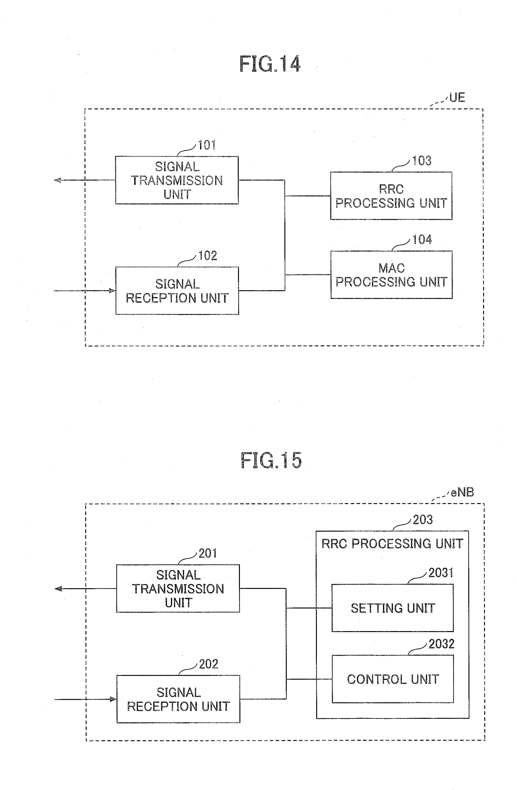
[0029] FIG. 14 is a diagram illustrating a functional configuration example of a user equipment according to each embodiment;
[0030] FIG. 15 is a diagram illustrating a functional configuration example of a base station according to each embodiment; and
[0031] FIG. 16 is a diagram illustrating a hardware configuration example of a user equipment and a base station according to each embodiment.
MODE(S) FOR CARRYING OUT THE INVENTION
[0032] Hereinafter, embodiments of the present invention will be described with reference to the drawings. The embodiments described hereinafter are merely exemplary ones, and the embodiments to which the present invention is applied are not limited to the following embodiments. For example, although it is assumed that the wireless communication system according to the embodiment is a system based on the LTE, the present invention is not limited to the LTE, but the present invention can be applied to other systems. In the specification and the claims, the term "LTE" is used in a broad sense including not only to the communication method corresponding to 3GPP Release 8 or 9 but also to the fifth generation (5G) communication method corresponding to 3GPP Release 10, 11, 12, 13, 14 or later.
First Embodiment
[0033] <System Configuration>
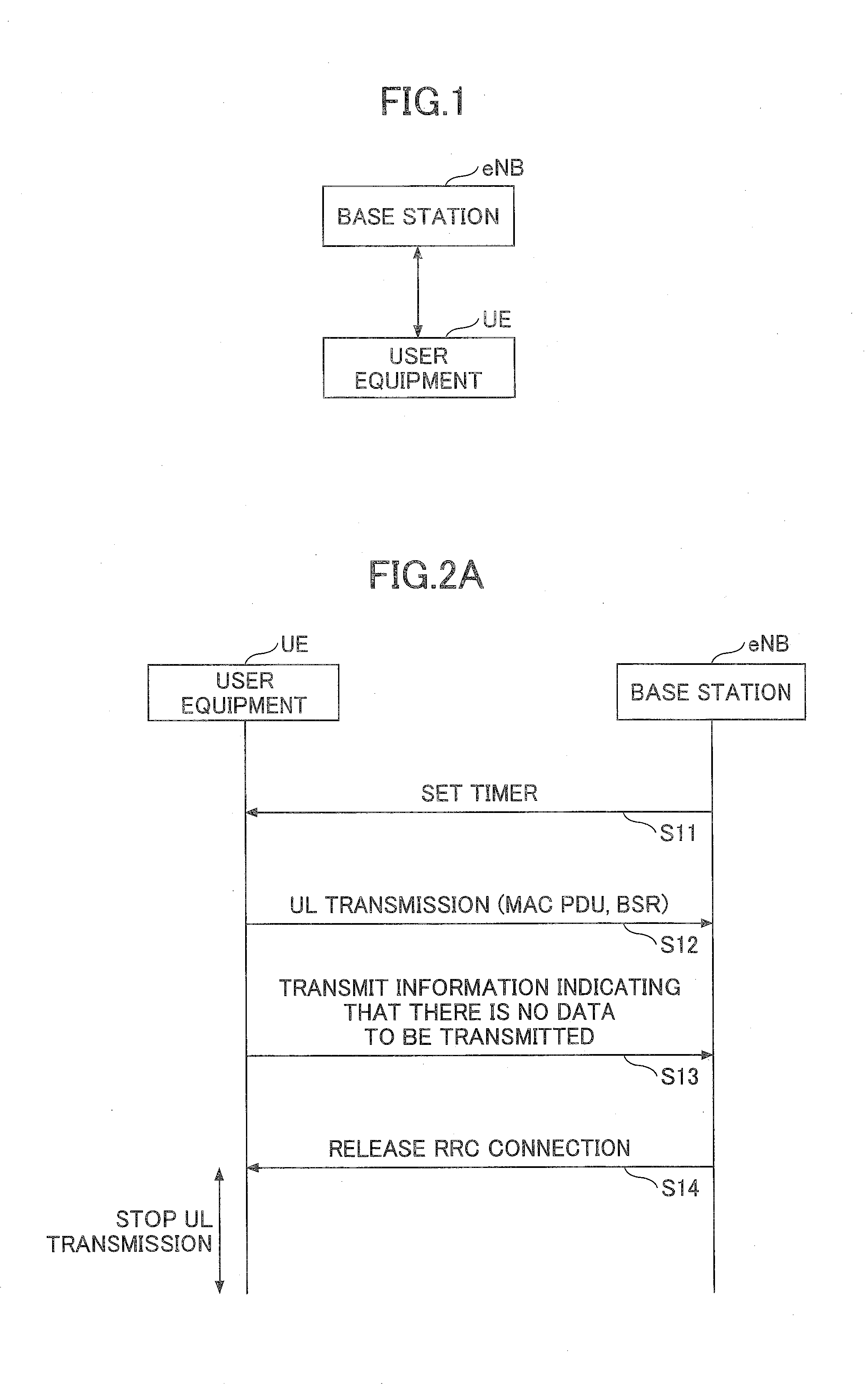
[0034] FIG. 1 is a diagram illustrating a configuration example of a wireless communication system according to an embodiment. As illustrated in FIG. 1, the wireless communication system according to the embodiment is configured to further include a base station eNB and a user equipment UE. In the example of FIG. 1, one base station eNB and one user equipment UE are illustrated, but a plurality of the base stations eNBs may be used, or a plurality of the user equipments UEs may be used.
[0035] The user equipment UE may be a terminal used by a general user such as a smartphone, may be an MTC terminal, or may be an NB-IoT terminal. Namely, the first embodiment can be applied to any type of user equipment UE.
[0036] <Processing Procedure>
[0037] (Processing Sequence)
[0038] In the first embodiment, the user equipment UE transmits information indicating that there is no UL data to be transmitted to the base station eNB and requests the base station eNB to release RRC connection. However, in the case of receiving the indication, the base station eNB side can be allowed to switch between whether or not to operate so as to release the RRC connection.
[0039] The information indicating that there is no UL data to be transmitted may be any information, but for example, the information may be MAC PDU not including buffer status report medium access control control element (BSR MAC CE) and including at least 2 bytes of padding or may be MAC PDU including BSR MAC CE indicating 0 byte.
[0040] FIG. 2A illustrates a sequence in a case where the base station eNB operates so as to release the RRC connection in the case of receiving the information indicating that there is no UL data to be transmitted.
[0041] In step S11, the base station eNB sets the timer value of a "timer for prohibiting transmission of an UL data for a predetermined period" to the user equipment UE by using broadcast information (SIB) or an RRC message. The "timer for prohibiting transmission of an UL data for a predetermined period" may be referred to as, for example, a "mo-DataSignallingExceptionalProhibittimer", but not limited thereto. In the first embodiment, by setting the timer to the user equipment UE, in the case of receiving the information indicating that there is no UL data to be transmitted, the user equipment UE is informed that the base station eNB operates so as to release the RRC connection. In addition, this operation may be referred to as, for example, "release Assistance Indication function".
[0042] In step S12, the user equipment UE transmits the UL data, and in a case where the transmission of all UL data is completed, in step S13, the information indicating that there is no UL data to be transmitted is transmitted to the base station eNB.
[0043] In step S14, the base station eNB releases the RRC connection. After the RRC connection is released, the user equipment UE operates so as not to request the establishment of the RRC connection to the base station eNB until the "timer for prohibiting transmission of an UL data for a predetermined period" expires. Namely, while the "timer for prohibiting transmission of an UL data for a predetermined period" is activated, the user equipment UE operates so as not to transmit the UL data by maintaining the state of RRC IDLE.
[0044] FIG. 2B illustrates a sequence in a case where the base station eNB does not release the RRC connection even in the case of receiving the information indicating that there is no UL data to be transmitted. Namely, the operations in FIG. 2B are the same as those in the LTE of the related art. The processing procedures of steps S21 and S22 are the same as those of steps S11 and S12, respectively, and the description thereof will be omitted. Unlike FIG. 2A, in the case of FIG. 2B, in the case of receiving the information indicating that there is no UL data to be transmitted, the base station eNB operates so as not to perform the scheduling of the UL resources (UL grant) similarly to the LTE in the related art and operates so as not to release the RRC connection.
[0045] (MAC Layer Processing)
[0046] Next, the processing procedure performed by the MAC layer of the user equipment UE according to the first embodiment will be described.
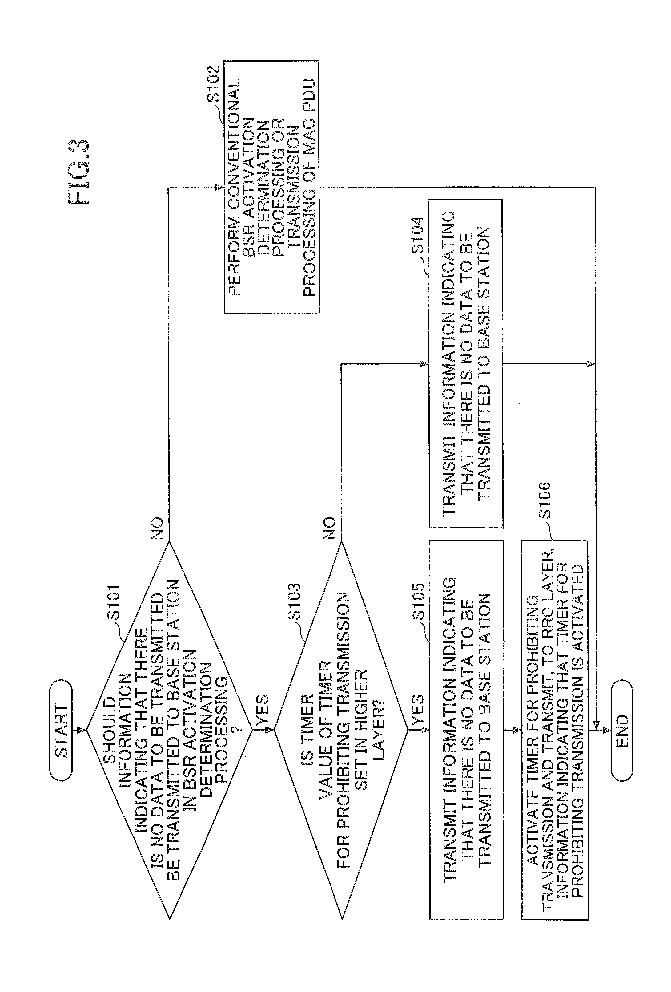
[0047] FIG. 3 is a flowchart illustrating an example of a processing procedure in the MAC layer. The MAC layer performs processing for determining whether or not to activate (trigger) buffer status report (BSR) in order to report the amount of UL data accumulated in the buffer in the MAC entity to the base station eNB. The flowchart illustrated in FIG. 3 illustrates a processing procedure performed when the processing for determining whether or not to activate the BSR (hereinafter, referred to as "BSR activation determination processing") is started.
[0048] In step S101, in a case where, as a result of the BSR activation determination processing, the user equipment UE determines that the information indicating that there is no UL data to be transmitted is to transmitted to the base station eNB, the processing proceeds to the processing procedure of step S103. In the other cases (a case where there is an UL data to be transmitted, and the like), the processing proceeds to the processing procedure of step S102.
[0049] In step S102, the user equipment UE performs the BSR activation determination processing in accordance with the regulations of the LTE in the related art and also performs transmission processing of MAC PDU including BSR MAC CE if necessary.
[0050] In step S103, the user equipment UE determines whether or not the timer value of the "timer for prohibiting transmission of an UL data for a predetermined period" is set in the higher layer (RRC layer). In a case where the timer value is set, the processing proceeds to step S105, and in a case where the timer value is not set, the processing proceeds to step S104.
[0051] In step S104, the user equipment UE transmits, to the base station eNB, the information indicating that there is no UL data to be transmitted. In this case, as described in FIG. 2(b), the base station eNB operates so as not to release the RRC connection even in a case where receiving the information indicating that there is no UL data to be transmitted.
[0052] In step S105, the user equipment UE transmits, to the base station eNB, the information indicating that there is no UL data to be transmitted. After transmitting, to the base station eNB, the information indicating that there is no UL data to be transmitted, in step S106, the user equipment UE activates (starts) the "timer for prohibiting transmission of an UL data for a predetermined period" and transmits, to the RRC layer, information indicating that the timer is activated.
[0053] (RRC Layer Processing)
[0054] Next, a processing procedure performed by the RRC layer of the user equipment UE according to the first embodiment will be described.
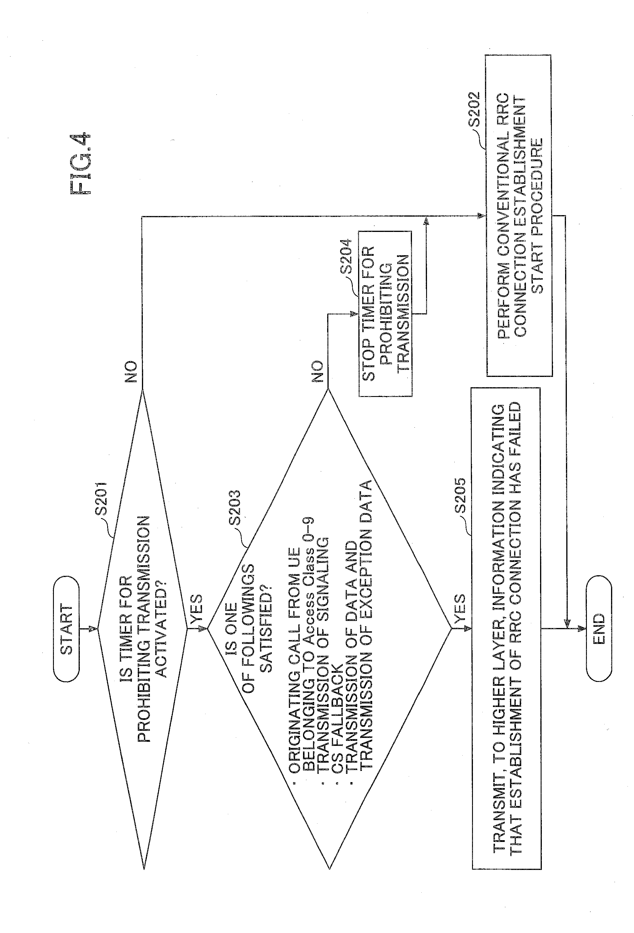
[0055] FIG. 4 is a flowchart illustrating an example of a processing procedure in the RRC layer. The processing procedure illustrated in FIG. 4 is performed in the RRC IDLE state in a case where the higher layer (NAS (Non Access Stratum) layer) requests the RRC layer to establish the RRC connection.
[0056] In step S201, the user equipment UE determines whether the "timer for prohibiting transmission of an UL data for a predetermined period" is activated. In a case where the timer is activated, the processing proceeds to the process procedure of step S203, and in a case where the timer is not activated, the processing proceeds to the process procedure of step S202.
[0057] In step S202, the user equipment UE executes a RRC connection establishment start procedure defined in the 3GPP specification in the related art.
[0058] In step S203, the user equipment UE determines whether or not the establishment of the RRC connection is requested from the higher layer (NAS layer) for the purpose of an originating call (mobile originating call) from the UEs belonging to Access Class 0-9, transmission of signaling (mobile originating signaling), CS fallback (mobile originating CS fallback), transmission of exception data (mobile originating exception data), and transmission of data (mobile originating data). Therefore, in the case for the reason, the processing proceeds to the processing procedure of step S204, and in the case for the other reasons (for example, an incoming call, an originating call from a UE belonging to the Access Class 11-15, an emergency call, or the like), the processing proceeds to the processing procedure of step S205.
[0059] In step S204, the user equipment UE stops the "timer for prohibiting transmission of an UL data for a predetermined period" and executes the RRC connection establishment start procedure defined in the 3GPP specification in the related art in step S202, so that the user equipment UE performs receiving an incoming call, originating a call from the UE belonging to the Access Class 11-15 and originating an emergency call. In addition, stopping the "timer for prohibiting transmission of an UL data for a predetermined period" is to avoid the state where the timer is operating irrespective of RRC CONNECTED. If such a condition is permitted, the processing procedure of step S204 may be omitted, and the processing may proceed to step S202.
[0060] In step S205, the user equipment UE transmits, to the higher layer (NAS layer), information indicating that the establishment of the RRC connection has failed (namely, the RRC connection cannot be established since the timer is activated).
[0061] (Specification Change Example)
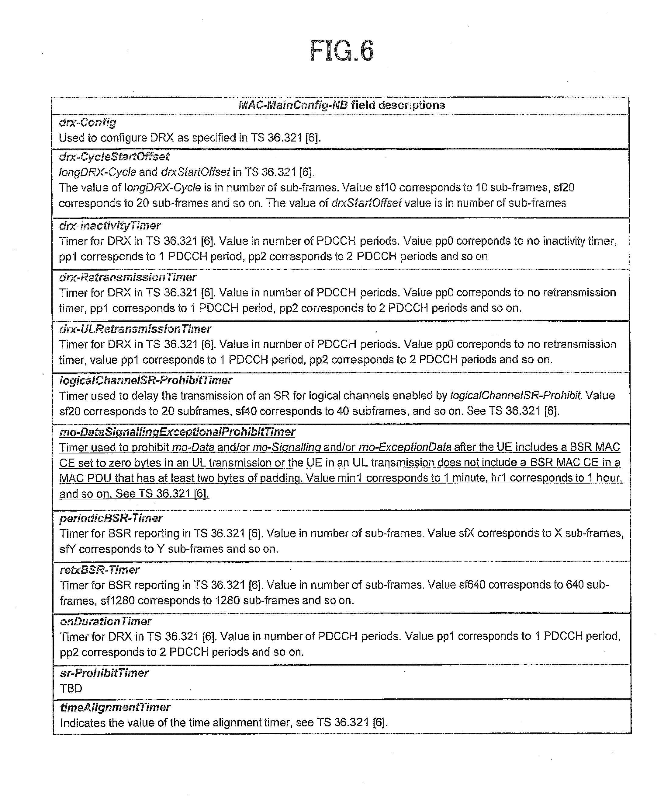
[0062] A specification change example of the 3GPP specification corresponding to the processing procedure described above is illustrated. The underlined portions in FIGS. 5 and 6 illustrate a specification change example (TS 36.331) of information elements for setting the timer value of the "timer for prohibiting transmission of an UL data for a predetermined period" to the user equipment UE. In the example of FIGS. 5 and 6, although an example of the information elements (MAC-MainConfig-NB information elements) indicating the MAC layer setting for the user equipment UE corresponding to a narrow band (NB) is illustrated, since the first embodiment can be applied to any user equipment UE, the modified example of the underlined portions in FIGS. 5 and 6 may be included in the information elements (MAC-MainConfig information elements) indicating the MAC layer setting for the normal user equipment UE.
[0063] In addition, the information elements for setting the timer value of the "timer for prohibiting transmission of an UL data for a predetermined period" to the user equipment UE is set to the information elements indicating the MAC layer setting for the user equipment UE corresponding to the narrow band, it is possible to allow only the user equipment UE corresponding to the narrow band to execute the operations described in the first embodiment.
[0064] The underlined portions of FIG. 7 illustrate a specification change example (TS 36.331) relating to the operation of the RRC layer, and the underlined portions of FIG. 8 illustrate a specification change example (TS 36.321) relating to the operation of the MAC layer.
Modified Example 1
[0065] In the processing procedure described above, it is assumed that referring to the state (whether or not it is activated) of, activating, and stopping the "timer for prohibiting transmission of an UL data for a predetermined period" is performed by both the MAC layer and the RRC layer. On the other hand, in Modified Example 1, the referring to the state of the timer may be performed by only at the MAC layer, and the MAC layer transmits the state of the timer to the RRC layer. More specifically, in the case of detecting that the "timer for prohibiting transmission of an UL data for a predetermined period" expires, the MAC layer of the user equipment UE transmits, to the higher layer (RRC layer), information indicating that the "timer for prohibiting transmission of an UL data for a predetermined period" is stopped.
[0066] (Specification Change Example)
[0067] FIG. 9 illustrates a specification change example (TS 36.321) relating to the operations of the MAC layer corresponding to Modified Example 1. The specification change examples of FIGS. 5 to 8 are also applied to Modified Example 1.
Modified Example 2
[0068] In Modified Example 2, referring to the state of, activating, and stopping the "timer for prohibiting transmission of an UL data for a predetermined period" are all performed only in the RRC layer. In addition, the RRC layer transmits, to the MAC layer, the state of the timer.
[0069] In Modified Example 2, in the processing procedure of step S106 in FIG. 3, the user equipment UE performs the processing of notifying (indicating) the high layer (RRC layer) that the information indicating that there is no data to be transmitted is transmitted to the base station instead of the processing of "activating (starting) the "timer for prohibiting transmission of an UL data for a predetermined period" and notifying the high layer (RRC layer) that the timer is activated".
[0070] In addition, in the case of receiving, from the MAC layer, the notification that information indicating that there is no data to be transmitted is transmitted to the base station, the RRC layer activates the "timer for prohibiting transmission of an UL data for a predetermined period".
[0071] (Specification Change Example)
[0072] FIG. 10 illustrates a specification change example (TS 36.331) relating to the operation of the RRC layer corresponding to Modified Example 2. In addition, FIG. 11 illustrates a specification change example (TS 36.321) relating to the operation of the MAC layer corresponding to Modified Example 2. The specification change examples of FIGS. 5 to 7 are also applied to Modified Example 2.
[0073] <Supplementary Matters Relating to Processing Procedure of First Embodiment>
[0074] In the processing procedure of the first embodiment described above, the type of the "UL data" that cannot be transmitted while the "timer for prohibiting transmission of an UL data for a predetermined period" is activated may be all the types such as an originating call (mobile originating call) from the UEs belonging to Access Class 0-9, transmission of signaling (mobile originating signaling), CS fallback (mobile originating CS fallback), transmission of exception data (mobile originating exception data), and transmission of data (mobile originating data) or may be a portion of these types.
[0075] In the latter case, in step S203 of FIG. 4, only in a case where a higher layer (NAS layer) requests the user equipment UE to establish the RRC connection in order to transmit a type of the UL data that cannot be transmitted while the timer is activated, the processing proceeds to the processing procedure of step S205. As an example, in a case where the establishment of the RRC connection is requested for the purpose of the CS fallback in step S203 of FIG. 4, the processing may proceed to the processing procedure of step S204 instead of proceeding to the processing procedure of step S205.
[0076] In addition, the type of "UL data" that cannot be transmitted while the "timer for prohibiting transmission of an UL data for a predetermined period" is activated is not limited to the above-described type, but another type may be included. For example, in a case where the establishment of the RRC connection is requested for the purpose of a VoLTE call (Voice over LTE) of voice service by IMS and a ViLTE call (Video over LTE) of video service by the IMS in step S203 of FIG. 4, the processing may proceed to the processing procedure of S205. In addition, with respect to the VoLTE call and the ViLTE call, the processing may proceed to step S204 instead of step S205.
[0077] In the case of receiving, from the base station eNB, an explicit notification that a function according to the embodiment (a function of operating so as to release the RRC connection in the case of receiving the notification that there is no UL data to be transmitted ("release Assistance Indication function")) is stopped, the user equipment UE may be allowed to stop the "timer for prohibiting transmission of an UL data for a predetermined period". The explicit notification may be used, for example, in a case where an RRC message (RRC Connection setup, RRC Connection Reconfiguration, or the like) indicating that the "Release Assistance Indication function" is to be stopped (released) is received from the base station eNB.
[0078] Heretofore, the processing procedure performed by the wireless communication system according to the first embodiment has been described. According to the first embodiment, in the case of receiving, from the user equipment UE, the information indicating that there is no UL data to be transmitted, the base station eNB can be allowed to switch between whether or not to operate so as to release the RRC connection.
[0079] In addition, since the user equipment UE operates so as not to transmit the UL data while the "timer for prohibiting transmission of an UL data for a predetermined period" is activated, frequent repetition of the release and establishment of the RRC connection can be prevented, so that it possible to suppress an increase in signaling amount.
Second Embodiment
[0080] Subsequently, a second embodiment will be described. In the first embodiment, the user equipment UE is configured so as not to transmit the UL data while the "timer for prohibiting transmission of an UL data for a predetermined period" is activated. On the other hand, in the second embodiment, the base station eNB sets, to the user equipment UE, a "timer for prohibiting notification that there is no UL data to be transmitted for a predetermined period" instead of the "timer for prohibiting transmission of an UL data for a predetermined period", and the user equipment UE is configured so as not to transmit, to the base station eNB, the information indicating that there is no UL data to be transmitted while the "timer for prohibiting notification that there is no UL data to be transmitted for a predetermined period" (hereinafter, for the convenience of description, referred to as "transmission prohibit timer") is activated. Since the "information indicating that there is no UL data to be transmitted" is the same as that in the first embodiment, the description thereof will be omitted.
[0081] <System Configuration>
[0082] Since the system configuration is the same as that of the first embodiment, the description thereof will be omitted.
[0083] <Processing Procedure>
[0084] (Processing Sequence)
[0085] In the second embodiment, similarly to the first embodiment, the user equipment UE transmits, to the base station eNB, the information indicating that there is no UL data to be transmitted and requests the base station eNB to release the RRC connection. In addition, in the case of receiving the notification (indication), the base station eNB side can be allowed to switch between whether or not to operate so as to release the RRC connection.
[0086] FIG. 12 illustrates a sequence in a case where the base station eNB operates so as to release the RRC connection in the case of receiving the notification (indication) that there is no UL data to be transmitted.
[0087] In step S31, the base station eNB sets the timer value of the "transmission prohibit timer" to the user equipment UE by using the broadcast information (SIB) or the RRC message. In the second embodiment, similarly to the first embodiment, by setting the timer to the user equipment UE, in the case of receiving the notification that there is no UL data to be transmitted, the user equipment UE is informed that the base station eNB operates to release the RRC connection. In addition, similarly to the first embodiment, this operation may be referred to as, for example, "release Assistance Indication function".
[0088] The timer value of the "transmission prohibit timer" may be included in an information element (MAC-MainConfig-NB information element) indicating the MAC layer setting for the user equipment UE corresponding to the narrow band or an information element (MAC-MainConfig information element) indicating the MAC layer setting for the normal user equipment UE.
[0089] In step S32, the user equipment UE transmits UL data, and in a case where the transmission of all the UL data is completed, in step S33, the user equipment transmits, to the base station eNB, the information indicating that there is no UL data to be transmitted. In addition, after transmitting, to the base station eNB, the information indicating that there is no UL data to be transmitted, the user equipment UE activates the "transmission prohibit timer". In step S34, the base station eNB releases the RRC connection.
[0090] Until the transmission prohibit timer expires, even in a case where there is no UL data to be re-transmitted, the user equipment UE is configured so as not to transmit, to the base station eNB, the information indicating that there is no UL data to be transmitted. Namely, although the transmission itself of the UL data is not prohibited even while the transmission prohibit timer is activated, after the transmission of the UL data is completed, the transmission of the information indicating that there is no UL data to be transmitted to the base station eNB is prohibited.
[0091] (MAC Layer Processing)
[0092] Subsequently, a processing procedure performed by the MAC layer of the user equipment UE according to the second embodiment will be described.
[0093] FIG. 13 is a flowchart illustrating an example of a processing procedure in the MAC layer. The flowchart illustrated in FIG. 13 illustrates the processing procedure performed in a case where the BSR activation determination processing is started similarly to FIG. 3 described in the first embodiment.
[0094] In step S301, in a case where, as a result of the BSR activation determination processing, the user equipment UE determines that the information indicating that there is no UL data to be transmitted is transmitted to the base station eNB, the processing proceeds to the processing procedure of step S303. In the other cases (a case where there is an UL data to be transmitted, and the like), the processing proceeds to the processing procedure of step S302.
[0095] In step S302, the user equipment UE performs the BSR activation determination processing in accordance with the regulations of the LTE in the related art and also performs transmission processing of MAC PDU including the BSR MAC CE if necessary.
[0096] In step S303, the user equipment UE determines whether or not the timer value of the "transmission prohibit timer" is set in the higher layer (RRC layer). In a case where the timer value is set, the processing proceeds to the process procedure of step S305, and in a case where the timer value is not set, the processing proceeds to the process procedure of step S304.
[0097] In step S304, the user equipment UE transmits, to the base station eNB, the information indicating that there is no UL data to be transmitted. In this case, as described with reference to FIG. 2(b) of the first embodiment, even in the case of receiving the notification that there is no UL data to be transmitted, the base station eNB operates so as not to release the RRC connection.
[0098] In step S305, the user equipment UE determines whether or not the "transmission prohibit timer" is activated. In a case where the "transmission prohibit timer" is activated, the processing is ended, and in a case where the "transmission prohibit timer" not activated, the processing proceeds to step S306.
[0099] In step S306, the user equipment UE transmits, to the base station eNB, the information indicating that there is no UL data to be transmitted. After transmitting, to the base station eNB, the information indicating that there is no UL data to be transmitted, the user equipment UE activates (starts) the "transmission prohibit timer" in step S307.
[0100] <Supplementary to Processing Procedure According to Second Embodiment>
[0101] In the case of receiving, from the base station eNB an explicit notification that a function according to the embodiment (a function of operating so as to release the RRC connection in the case of receiving the notification (indication) that there is no UL data to be transmitted ("release Assistance Indication function")) is stopped, the user equipment UE may be allowed to stop the "transmission prohibit timer". The explicit notification may be used, for example, in a case where an RRC message (RRC Connection setup, RRC Connection Reconfiguration, or the like) indicating that the "Release Assistance Indication Function" is to be stopped (Released) is received from the base station eNB.
[0102] Heretofore, the processing procedure performed by the wireless communication system according to the second embodiment has been described. According to the second embodiment, in the case of receiving, from the user equipment UE, the information indicating that there is no UL data to be transmitted, the base station eNB can be allowed to switch between whether or not to operate so as to release the RRC connection.
[0103] In addition, since the user equipment UE operates so as not to transmit, to the base station eNB, the information indicating that there is no UL data to be transmitted while the "timer for prohibiting notification that there is no UL data to be transmitted for a predetermined period" is activated, frequent repetition of the release and establishment of the RRC connection can be prevented, so that it possible to suppress an increase in signaling amount.
Third Embodiment
[0104] Subsequently, a third embodiment will be described. In the third embodiment, in the case of receiving the notification that there is no UL data to be transmitted, the base station eNB sets the information " " indicating whether or not to operate so as to release the RRC connection (hereinafter, for the convenience of description, referred to as "operation Setting information") to the user equipment UE by using the broadcast information (SIB) or the RRC message (RRC Connection setup, RRC Connection Reconfiguration, or the like). In addition, the operation may be referred to as, for example, "release Assistance Indication function", similarly to the first and second embodiments.
[0105] The "operation setting information" may be included in an information element indicating the MAC layer setting for the user equipment UE corresponding to the narrow band (MAC-MainConfig-NB information element), or an information element indicating the MAC layer setting for the normal user equipment UE (MAC-MainConfig information element). The "operation setting information" may be referred to as, for example, "release Assistance Indication" or another name may be used.
[0106] In the third embodiment, unlike the first and second embodiments, the user equipment UE can perform transmission of a UL data and notification that there is no UL data to be transmitted without particular limitation. In other words, how to operate on the setting value of "operation setting information" depends on the implementation of the user equipment UE.
[0107] On the other hand, in a case where the "operation setting information" is set to "Operate (True, Enable, Setup)", the base station eNB having received the notification that there is no UL data to be transmitted operates to release the RRC connection. In addition, in a case where the "operation setting information" is set to "Not Operate (False, Disable, Release)", the base station eNB having received the notification that there is no UL data to be transmitted operates so as not to perform the scheduling (UL grant) of the UL resources and operates so as not to release the RRC connection similarly to the LTE in the related art.
[0108] Heretofore, the processing procedure performed by the wireless communication system according to the third embodiment has been described. According to the third embodiment, in the case of receiving, from the user equipment UE, the information indicating that there is no UL data to be transmitted, the base station eNB can be allowed to switch between whether or not to operate so as to release the RRC connection.
[0109] <<Functional Configuration>>
[0110] Hereinafter, a functional configuration example of the user equipment UE and the base station eNB which perform the operations of each embodiment of the present invention will be described.
[0111] (User Equipment)
[0112] FIG. 14 is a diagram illustrating a functional configuration example of a user equipment according to each embodiment. As illustrated in FIG. 14, the user equipment UE is configured to include a signal transmission unit 101, a signal reception unit 102, an RRC processing unit 103, and a MAC processing unit 104. In addition, FIG. 14 illustrates only the functional units particularly relating to the present invention in the user equipment UE, and the user equipment UE also has a function (not illustrated) for performing at least operation in accordance with the LTE.
[0113] The signal transmission unit 101 has a function of generating various types of signals of the physical layer from the signals of the higher layer to be transmitted from the user equipment UE and wirelessly transmitting the signals. In addition, the signal transmission unit 101 has a function of transmitting the uplink data after establishing the RRC connection in a case where a predetermined timer ("timer for prohibiting transmission of an UL data for a predetermined period") is not activated.
[0114] The signal reception unit 102 has a function of wirelessly receiving various types of signals from the base station eNB and acquiring signals of the higher layers from the received signals of the physical layer.
[0115] The RRC processing unit 103 has a function of performing processing of the RRC layer. In addition, the RRC processing unit 103 has a function of receiving the information for setting a value of a predetermined timer (information element for setting the timer value of the "timer for prohibiting transmission of an UL data for a predetermined period" or the "timer for prohibiting notification that there is no UL data to be transmitted for a predetermined period") from the base station eNB through the signal reception unit 102. In addition, in a case where the predetermined timer ("timer for prohibiting transmission of an UL data for a predetermined period") is activated, the RRC processing unit 103 does not establish the RRC connection so that no uplink data is transmitted from the signal transmission unit 101. In addition, in a case where the predetermined timer ("timer for prohibiting transmission of an UL data for a predetermined period") is not activated, the RRC processing unit 103 establishes the RRC connection according to the request of the higher layer (NAS layer).
[0116] The MAC processing unit 104 has a function of performing processing of the MAC layer. The MAC processing unit 104 may be allowed to activate a predetermined timer (a "timer for prohibiting transmission of an UL data for a predetermined period" or a "timer for prohibiting notification that there is no UL data to be transmitted for a predetermined period") in a case where the value of the predetermined timer is set from the base station eNB and in a case where the "information indicating that there is no uplink data to be transmitted" is transmitted to the base station eNB.
[0117] In addition, in a case where the value of the predetermined timer ("timer for prohibiting transmission of an UL data for a predetermined period") is set from the base station eNB and the "information indicating that there is no uplink data to be transmitted" is transmitted to the base station eNB, the MAC processing unit 104 may be allowed to notify the RRC processing unit 103 that the "information indicating that there is no uplink data to be transmitted" is transmitted to the base station eNB so as to allow the RRC processing unit 103 to activate the predetermined timer ("timer for prohibiting transmission of an UL data for a predetermined period").
[0118] In addition, until the predetermined timer ("timer for prohibiting notification that there is no UL data to be transmitted for a predetermined period") expires, the MAC processing unit 104 may be allowed not to transmit the "information indicating that there is no uplink data to be transmitted" to the base station eNB.
[0119] In addition, the signal transmission unit 101, the RRC processing unit 103, and the MAC processing unit 104 may be collectively referred to as a transmission unit. In addition, the signal reception unit 102 and the RRC processing unit 103 may be collectively referred to as a reception unit, or the signal reception unit 102, the RRC processing unit 103, and the MAC processing unit 104 may be collectively referred to as a reception unit.
[0120] (Base Station)
[0121] FIG. 15 is a diagram illustrating a functional configuration example of a base station according to each embodiment. As illustrated in FIG. 15, the base station eNB is configured to include a signal transmission unit 201, a signal reception unit 202, and an RRC processing unit 203. In addition, the RRC processing unit 203 is configured to further include a setting unit 2031 and a control unit 2032. In addition, FIG. 15 illustrates only the functional units particularly relating to the embodiment of the present invention in the base station eNB, and also has a function (not illustrated) for performing at least operation in accordance with the LTE. In addition, the functional configuration illustrated in FIG. 15 is merely an example. As long as the operation according to each embodiment can be executed, any functional division and any names of functional units may be available.
[0122] The signal transmission unit 201 has a function of generating various types of signals to be transmitted from the base station eNB and wirelessly transmitting the signals. The signal reception unit 202 has a function of wirelessly receiving various types of signals from the user equipment UE and acquiring signals of the higher layer from the received signals of the physical layer.
[0123] The RRC processing unit 203 has a function of performing processing of the RRC layer. The setting unit 2031 has a function of setting a value of predetermined information (a "timer for prohibiting transmission of an UL data for a predetermined period", a "timer for prohibiting notification that there is no UL data to be transmitted for a predetermined period", or an "operation setting information") to the user equipment UE. The control unit 2032 has a function of releasing the RRC connection with the user equipment UE in the case of setting the value of the predetermined information (the "timer for prohibiting transmission of an UL data for a predetermined period", the "timer for prohibiting notification that there is no UL data to be transmitted for a predetermined period", or the "operation setting information") to the user equipment UE and in the case of receiving the information indicating that there is no uplink data to be transmitted from the user equipment UE.
[0124] <Hardware Configuration>
[0125] The block diagrams (FIGS. 14 and 15) used in the description of the above-described embodiment illustrate the blocks of functional units. These functional blocks (constituent units) are realized by arbitrary combination of hardware and/or software. In addition, means for implementing each functional block is not particularly limited. Namely, each functional block may be realized by one physically and/or logically combined device.
[0126] Alternatively, two or more physically and/or logically separated devices may be directly and/or indirectly connected (for example, in a wired and/or wireless manner), and thus, each functional block may be realized by these plural devices.
[0127] For example, the base station eNB and the user equipment UE according to an embodiment of the present invention may function as a computer that performs processing of the signal transmission method according to the present invention. FIG. 16 is a diagram illustrating a hardware configuration example of the user equipment and the base station according to the embodiment. The above-described base station eNB and user equipment UE may be physically configured as a computer device including a processor 1001, a memory 1002, a storage 1003, a communication device 1004, an input device 1005, an output device 1006, a bus 1007, and the like.
[0128] In addition, in the following description, the term "device" can be replaced with a circuit, a device, a unit, or the like. The hardware configuration of the base station eNB and the user equipment UE may be configured to include one or a plurality of the respective devices illustrated in the drawings or may be configured not to include some devices.
[0129] Each function of the base station eNB and the user equipment UE is realized by allowing the processor 1001 to perform a calculation by allowing predetermined software (programs) to be loaded on hardware such as the processor 1001 and the memory 1002 and controlling communication by the communication device 1004 and reading and/or writing of data in the memory 1002 and the storage 1003.
[0130] The processor 1001 operates, for example, the operating system to control the whole computer. The processor 1001 may be configured with a central processing unit (CPU) including an interface with a peripheral device, a control device, an arithmetic device, a register and the like. For example, the signal transmission unit 101, the signal reception unit 102, the RRC processing unit 103, and the MAC processing unit 104 of the user equipment UE and the signal transmission unit 201, the signal reception unit 202, the RRC processing unit 203, the setting unit 2031, and control unit 2032 of the base station eNB may be realized by the processor 1001.
[0131] In addition, the processor 1001 reads a program (program code), a software module, or data from the storage 1003 and/or the communication device 1004 to the memory 1002 and executes various types of processing according to the program and the like. As the program, a program that allows a computer to execute at least a portion of the operation described in the above-described embodiment is used. For example, the signal transmission unit 101, the signal reception unit 102, the RRC processing unit 103, the MAC processing unit 104 of the user equipment UE and the signal transmission unit 201, the signal reception unit 202, the RRC processing unit 203, the setting unit 2031, and the control unit 2032 of the base station eNB may be realized by a control program that is stored in the memory 1002 and operates through the processor 1001, and other functional blocks may also be realized in the same manner. Although it has been described that the above-described various types of processing are executed by one processor 1001, the various types of processing may be executed simultaneously or sequentially by two or more processors 1001. The processor 1001 may be implemented with one or more chips. In addition, the program may be transmitted from the network via an electric communication line.
[0132] The memory 1002 is a computer-readable recording medium and is configured with, for example, at least one of a read only memory (ROM), an erasable programmable ROM (EPROM), an electrically erasable programmable ROM (EEPROM), and a random access memory (RAM). The memory 1002 may be referred to as a register, a cache, a main memory (main storage device), or the like. The memory 1002 can store executable programs (program codes), software modules, and the like for implementing the signal transmission method according to an embodiment of the present invention.
[0133] The storage 1003 is a computer-readable recording medium, and may be configured to include, for example, at least one of an optical disk such as a compact disc ROM (CD-ROM), a hard disk drive, a flexible disk, a magneto-optical disk (for example, a compact disk, a digital versatile disk, a Blu-ray (registered trademark) disk, or the like), a smart card, a flash memory (for example, a card, a stick, a key drive, or the like), a floppy (registered trademark) disk, a magnetic strip, and the like. The storage 1003 may be referred to as an auxiliary storage device. The above-described storage medium may be, for example, a database including the memory 1002 and/or the storage 1003, a server, or other appropriate medium.
[0134] The communication device 1004 is hardware (transmission/reception device) for performing communication between computers via a wired and/or wireless network and is also referred to as a network device, a network controller, a network card, a communication module, or the like. For example, the signal transmission unit 101 and the signal reception unit 102 of the user equipment UE and the signal transmission unit 201 and the signal reception unit 202 of the base station eNB may be realized by the communication device 1004.
[0135] The input device 1005 is an input device (for example, a keyboard, a mouse, a microphone, a switch, a button, a sensor, or the like) that receives an input from the outside. The output device 1006 is an output device (for example, a display, a speaker, an LED lamp, or the like) that performs an output to the outside. In addition, the input device 1005 and the output device 1006 may be configured to be integrated (for example, a touch panel).
[0136] In addition, the respective devices such as the processor 1001 and the memory 1002 are connected via the bus 1007 for communicating information. The bus 1007 may be configured as a single bus or may be configured as different buses between the devices.
[0137] In addition, the base station eNB and the user equipment UE may be be configured to include hardware such as a microprocessor, a digital signal processor (DSP), an application specific integrated circuit (ASIC), a programmable logic device (PLD), and a field programmable gate array (FPDA) and may be realized by some or all of the functional blocks. For example, the processor 1001 may be implemented with at least one of the above hardware.
SUMMARY
[0138] As described above, according to an embodiment, there is provided a user equipment in a wireless communication system including a base station and the user equipment, including: a reception unit configured to receive information for setting a value of a predetermined timer from the base station; and a transmission unit configured to transmit an uplink data in a case where the timer is not activated, in which the transmission unit activates the predetermined timer in a case where the value of the predetermined timer is set from the base station and information indicating that there is no uplink data to be transmitted is transmitted to the base station. According to the user equipment UE, provided is a technique capable of suppressing an increase in signaling amount in the wireless communication system.
[0139] In addition, according to an embodiment, there is provided a user equipment in a wireless communication system including a base station and the user equipment, including: a reception unit configured to receive information for setting a value of a predetermined timer from the base station; and a transmission unit configured to transmit an uplink data, in which the transmission unit activates the predetermined timer in a case where the predetermined timer value is set from the base station and information indicating that there is no uplink data to be transmitted is transmitted to the base station, and the transmission unit does not transmit the information indicating that there is no uplink data to be transmitted to the base station until the predetermined timer expires. According to the user equipment UE, provided is a technique capable of suppressing an increase in signaling amount in the wireless communication system.
[0140] In addition, the information for setting the value of the predetermined timer may be included in an information element indicating the MAC layer setting.
[0141] In addition, the information for setting the value of the predetermined timer may be included in an information element indicating the MAC layer setting for the user equipment corresponding to the narrow band. By doing so, only the user equipment UE corresponding to the narrow band can be allowed to execute the operation described in the embodiment.
[0142] In addition, according to an embodiment, there is provided a base station in a wireless communication system including the base station and a user equipment, including: a setting unit configured to set predetermined information to the user equipment; and a control unit configured to release RRC connection with the user equipment in the case of setting the predetermined information to the user equipment and in the case of receiving information indicating that there is no uplink data to be transmitted from the user equipment. According to the base station eNB, provided is a technique capable of suppressing an increase in signaling amount in the wireless communication system.
[0143] In addition, according to an embodiment, there is provided a signal transmission method executed by a user equipment in a wireless communication system including a base station and the user equipment, the method including steps of: receiving information for setting a value of a predetermined timer from the base station; transmitting an uplink data in a case where the predetermined timer is not activated; and activating the predetermined timer in a case where the value of the predetermined timer is set from the base station and information indicating that there is no uplink data to be transmitted is transmitted to the base station. According to the signal transmission method, provided is a technique capable of suppressing an increase in signaling amount in the wireless communication system.
[0144] In addition, according to an embodiment, there is provided a signal transmission method executed by a user equipment in a wireless communication system including a base station and the user equipment, the method including steps of: receiving information for setting a value of a predetermined timer from the base station; transmitting uplink data; activating the predetermined timer in a case where the value of the predetermined timer is set from the base station and information indicating that there is no uplink data to be transmitted is transmitted to the base station; and not transmitting the information indicating that there is no uplink data to be transmitted to the base station until the predetermined timer expires. According to the signal transmission method, provided is a technique capable of suppressing an increase in signaling amount in the wireless communication system.
Supplement to Embodiments
[0145] Notification of information is not limited to the aspects and embodiments described in the specification, but the notification of information may be performed in other methods. For example, the notification of information may be performed by physical layer signaling (for example, downlink control information (DCI), uplink control information (UCI)), higher layer signaling (for example, radio resource control (RRC) signaling, medium access control (MAC) signaling, broadcast information (master information block (MIB), system information block (SIB))), other signals, or a combination thereof. In addition, the RRC signaling may be referred to as an RRC message, for example, an RRC connection setup message, an RRC connection reconfiguration message, or the like.
[0146] Each aspect/embodiment described in the specification can be applied to long term evolution (LTC), LTE-advanced (LTE-A), SUPER 3G, IMT-Advanced, 4G, 5G, future radio access (FRA), W-CDMA (registered trademark), GSM (registered trademark), CDMA2000, ultra mobile broadband (UMB), IEEE 802.11 (Wi-Fi), IEEE 802.16 (WiMAX), IEEE 802.20, ultra-wideband (UWB), Bluetooth (registered trademark), any other systems using an appropriate system and/or next generation systems expanded on the basis of these systems.
[0147] In addition, processing procedures, sequences, flowcharts, and the like of each aspect and embodiment described in the specification may be exchanged as long as there is no inconsistency. For example, for the methods described in the specification, the elements of the various steps are presented in an exemplary order and are not limited to a specific order presented.
[0148] In some cases, the specific operations performed by the base station in the specification may be performed by upper nodes. It is apparent that, in a network configured with one or more network nodes having a base station, various operations performed for communication with a terminal may be performed by the base station and/or other network nodes other than the base station (for example, MME, S-GW, or the like is considered, but not limited thereto). In the above description, the case where there is one network node other than the base station is described as an example, but a combination of a plurality of other network nodes (for example, MME and S-GW) may be used.
[0149] Input/output information or the like may be stored in a specific site (for example, a memory) or may be managed in a management table. The input/output Information or the like may be overwritten, updated, or additionally written. The output information or the like may be deleted. The input information or the like may be transmitted to another device.
[0150] In some cases, the user equipment UE may be referred to as a subscriber station, a mobile unit, a subscriber unit, a wireless unit, a remote unit, a mobile device, a wireless device, a wireless communication device, a remote device, a mobile subscriber station, an access terminal, a mobile terminal, a wireless terminal, a remote terminal, a handset, a user agent, a mobile client, a client, or some other appropriate term by the skilled in the art.
[0151] The phrase "based on" used in the specification does not denote "based only on" unless explicitly stated otherwise. In other words, the phrase "based on" denotes both "based only on" and "based at least on".
[0152] Each aspect and embodiment described in the specification may be used alone, may be used in combination thereof, or may be used by being exchanged according to the execution. In addition, notification of predetermined information (for example, notification of "being X") is not limited to being performed explicitly, but the notification may be performed implicitly (for example, not notifying the predetermined information).
[0153] Determination or judgment may be performed according to a value (0 or 1) represented by a bit, may be performed according to a boolean value (true or false), or may be performed according to comparison of numerical values (e.g., comparison with a predetermined value).
[0154] It should be noted that the terms described in the present specification and/or terms necessary for understanding the present specification may be replaced by terms that have the same or similar meaning. For example, a channel and/or a symbol may be a signal. Further, a signal may be a message.
[0155] As used herein, the term "determining" may encompasses a wide variety of actions. For example, "determining" may be regarded as calculating, computing, processing, deriving, investigating, looking up (e.g., looking up in a table, a database or another data structure), ascertaining and the like. Also, "determining" may be regarded as receiving (e.g., receiving information), transmitting (e.g., transmitting information), inputting, outputting, accessing (e.g., accessing data in a memory) and the like. Also, "determining" may be regarded as resolving, selecting, choosing, establishing, comparing and the like. That is, "determining" may be regarded as a certain type of action related to determining.
[0156] Information, a signal, etc., described in the present specification may be represented by using any one of the various different techniques. For example, data, an instruction, a command, information, a signal, a bit, a symbol, a chip or the like described throughout in the present specification may be represented by voltage, current, electromagnetic waves, magnetic fields or a magnetic particle, optical fields or a photon, or any combination thereof.
[0157] Although the present invention has been described above in detail, it will be apparent to the skilled in the art that the present invention is not limited to the embodiments described herein. The present invention can be implemented as changes and modifications without departing from the spirit and scope of the present invention as defined by the scope of the claims. Accordingly, the description of the specification is provided for the purpose of illustration and description and does not have any restrictive meaning with respect to the present invention.
[0158] In the embodiment, the signal transmission unit 101, the RRC processing unit 103, and the MAC processing unit 104 are examples of a transmission unit. In addition, the signal reception unit 102 and the RRC processing unit 103 are examples of the reception unit. A "timer for prohibiting transmission of an UL data for a predetermined period" or a "timer for prohibiting notification that there is no UL data to be transmitted for a predetermined period" is an example of a predetermined timer. A "timer for prohibiting transmission of an UL data for a predetermined period", a "timer for prohibiting notification that there is no UL data to be transmitted for a predetermined period", or "operation setting information" is an example of predetermined information.
[0159] The present application is based on and claims priority to Japanese patent application No. 2016-101953 filed on May 20, 2016, and Japanese patent application No. 2016-105567 filed on May 26, 2016, the entire contents of which are hereby incorporated by reference.
EXPLANATIONS OF LETTERS OR NUMERALS
[0160] UE user equipment [0161] eNB base station [0162] 101 signal transmission unit [0163] 102 signal reception unit [0164] 103 RRC processing unit [0165] 104 MAC processing unit [0166] 201 signal transmission unit [0167] 202 signal reception unit [0168] 203 RRC processing unit [0169] 2031 setting unit [0170] 2032 control unit [0171] 1001 processor [0172] 1002 memory [0173] 1003 storage [0174] 1004 communication device [0175] 1005 input device [0176] 1006 output device
* * * * *
D00000
D00001
D00002
D00003
D00004
D00005
D00006
D00007
D00008
D00009
D00010
D00011
D00012

D00013

D00014
D00015

XML
uspto.report is an independent third-party trademark research tool that is not affiliated, endorsed, or sponsored by the United States Patent and Trademark Office (USPTO) or any other governmental organization. The information provided by uspto.report is based on publicly available data at the time of writing and is intended for informational purposes only.
While we strive to provide accurate and up-to-date information, we do not guarantee the accuracy, completeness, reliability, or suitability of the information displayed on this site. The use of this site is at your own risk. Any reliance you place on such information is therefore strictly at your own risk.
All official trademark data, including owner information, should be verified by visiting the official USPTO website at www.uspto.gov. This site is not intended to replace professional legal advice and should not be used as a substitute for consulting with a legal professional who is knowledgeable about trademark law.