Lithium-ion Battery
Shi; Qiao ; et al.
U.S. patent application number 16/316618 was filed with the patent office on 2019-10-03 for lithium-ion battery. The applicant listed for this patent is SHENZHEN CAPCHEM TECHNOLOGY CO., LTD.. Invention is credited to Shiguang Hu, Xionggui Lin, Qiao Shi, Jiaojiao Yun.
| Application Number | 20190305365 16/316618 |
| Document ID | / |
| Family ID | 62195667 |
| Filed Date | 2019-10-03 |

| United States Patent Application | 20190305365 |
| Kind Code | A1 |
| Shi; Qiao ; et al. | October 3, 2019 |
LITHIUM-ION BATTERY
Abstract
A lithium-ion battery, comprising a cathode, an anode, and a non-aqueous electrolyte; the cathode comprises a cathode active material and a metal oxide and/or metal fluoride coating which covers the surface of the cathode active material; the cathode active material is at least one of materials illustrated in general formula I or II: formula I: Li.sub.xNi.sub.yM.sub.1-yO.sub.2, wherein 0.5.ltoreq.x.ltoreq.1.2, 0.5.ltoreq.y.ltoreq.1, and M is selected from at least one of Co, Mn, Al, Ti, Fe, Zn, Zr, Cr, and formula II: Li.sub.kCo.sub.zL.sub.1-zO.sub.2, wherein 0.5.ltoreq.k.ltoreq.1.2, 0.5<z.ltoreq.1, and L is selected from at least one of Ni, Mn, Al, Ti, Fe, Zn, Zr, Cr. According to the lithium-ion battery, the charge cut-off voltage of the lithium-ion battery reaches 4.3 V or more by means of a synergistic effect of the unsaturated phosphate compounds and the coating at the surface of the cathode active material.
| Inventors: | Shi; Qiao; (Shenzhen, Guangdong, CN) ; Hu; Shiguang; (Shenzhen, Guangdong, CN) ; Lin; Xionggui; (Shenzhen, Guangdong, CN) ; Yun; Jiaojiao; (Shenzhen, Guangdong, CN) | ||||||||||
| Applicant: |
|
||||||||||
|---|---|---|---|---|---|---|---|---|---|---|---|
| Family ID: | 62195667 | ||||||||||
| Appl. No.: | 16/316618 | ||||||||||
| Filed: | December 29, 2016 | ||||||||||
| PCT Filed: | December 29, 2016 | ||||||||||
| PCT NO: | PCT/CN2016/113032 | ||||||||||
| 371 Date: | January 9, 2019 |
| Current U.S. Class: | 1/1 |
| Current CPC Class: | H01M 4/62 20130101; H01M 4/366 20130101; H01M 4/525 20130101; H01M 4/587 20130101; H01M 2300/0025 20130101; H01M 10/0525 20130101; H01M 4/386 20130101; H01M 10/0567 20130101 |
| International Class: | H01M 10/0525 20060101 H01M010/0525; H01M 4/525 20060101 H01M004/525; H01M 10/0567 20060101 H01M010/0567; H01M 4/36 20060101 H01M004/36; H01M 4/587 20060101 H01M004/587; H01M 4/38 20060101 H01M004/38 |
Foreign Application Data
| Date | Code | Application Number |
|---|---|---|
| Nov 25, 2016 | CN | 201611055609.4 |
Claims
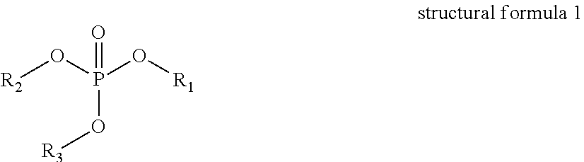
1. A lithium-ion battery, comprising a battery case, and a cathode, an anode and a non-aqueous electrolyte inside the battery case; the cathode comprising a cathode active material and a coating layer coated on a surface of the cathode active material; the cathode active material having at least one of the component represented by general formula 1 or general formula 2, Li.sub.xNi.sub.yM.sub.1-yO.sub.2, general formula 1: wherein 0.5.ltoreq.x.ltoreq.1.2, 0.5.ltoreq.y.ltoreq.1, and M is at least one selected from the group consisting of Co, Mn, Al, Ti, Fe, Zn, Zr, and Cr; Li.sub.kCo.sub.zL.sub.1-zO.sub.2, general formula 2: wherein 0.5.ltoreq.k.ltoreq.1.2, 0.5<z.ltoreq.1, L is at least one selected from the group consisting of Ni, Mn, Al, Ti, Fe, Zn, Zr, and Cr; the coating layer is a metal oxide and/or a metal fluoride; the anode includes an anode active material selected from at least one of graphite or a silicon-containing carbon material; the non-aqueous electrolyte contains at least one of the unsaturated phosphate ester compounds represented by structural formula 1, ##STR00002## wherein R.sub.1, R.sub.2 and R.sub.3 are each independently selected from a saturated hydrocarbon group, an unsaturated hydrocarbon group or a halogenated hydrocarbon group having 1 to 5 carbon atoms, and at least one of R.sub.1, R.sub.2 and R.sub.3 is an unsaturated hydrocarbon group.
2. The lithium-ion battery according to claim 1, wherein in general formula 1, 0.8.ltoreq.x.ltoreq.1.1, and 0.8.ltoreq.y.ltoreq.1; and in general formula 2, 0.8.ltoreq.z.ltoreq.1.
3. The lithium-ion battery according to claim 1, wherein the cathode active material represented by general formula 1 is one selected from the group consisting of LiNi.sub.0.5Co.sub.0.2Mn.sub.0.3O.sub.2, LiNi.sub.0.6Co.sub.0.2Mn.sub.0.2O.sub.2, LiNi.sub.0.8Co.sub.0.1Mn.sub.0.1O.sub.2, LiNi.sub.0.8Co.sub.0.2O.sub.2, and LiNi.sub.0.8Co.sub.0.15Al.sub.0.05O.sub.2; the cathode active material represented by general formula 2 is selected from LiCoO.sub.2.
4. The lithium-ion battery according to claim 1, wherein the material of the coating layer is an oxide or fluoride of at least one of Zn, Mg, Al, Zr, Cr, Ti, Ag, Nb, Y, Sr, W, Mo, Pb, Cd, Ca, Ba, or Sn.
5. The lithium-ion battery according to claim 4, wherein the material of the coating layer is at least one selected from the group consisting of ZnO, MgO, Al.sub.2O.sub.3, ZrO.sub.2, Cr.sub.2O.sub.3, AlF.sub.3, or TiO.sub.2.
6. The lithium-ion battery according to claim 1, wherein the content of the coating layer is 0.1 to 5% based on the total weight of the cathode active material and the coating layer.
7. The lithium-ion battery according to claim 1, wherein in structural formula 1, the saturated hydrocarbon group is one selected from the group consisting of methyl, ethyl, propyl, isopropyl, or butyl; the unsaturated hydrocarbon group is one selected from the group consisting of vinyl, allyl, 3-butenyl, isobutenyl, 4-pentenyl, ethynyl, propargyl, 3-butynyl, or 1-methyl-2-propynyl; and the halogenated hydrocarbon group is one selected from the group consisting of monofluoromethyl, difluoromethyl, trifluoromethyl, 2,2,2-trifluoroethyl, 2,2-difluoroethyl, 2,2,2-trifluoroethyl, 3,3-difluoropropyl, 3,3,3-trifluoropropyl, or hexafluoroisopropyl.
8. The lithium-ion battery according to claim 7, wherein the unsaturated phosphate ester compound is one or more selected from the group consisting of tripropargyl phosphate, dipropargyl methyl phosphate, dipropargyl ethyl phosphate, dipropargyl propyl phosphate, dipropargyl trifluoromethyl phosphate, dipropargyl 2,2,2-trifluoroethyl phosphate, dipropargyl 3,3,3-trifluoropropyl phosphate, dipropargyl hexafluoroisopropyl phosphate, triallyl phosphate, diallyl methyl phosphate, diallyl ethyl phosphate, diallylpropyl phosphate, diallyl trifluoromethyl phosphate, diallyl 2,2,2-trifluoroethyl phosphate, diallyl 3,3,3-trifluoropropyl phosphate, or diallyl hexafluoroisopropyl phosphate.
9. The lithium-ion battery according to claim 7, wherein in the non-aqueous electrolyte, the content of the unsaturated phosphate ester compound is from 0.1% to 5%.
10. The lithium-ion battery according to claim 1, wherein the lithium-ion battery has a charge cut-off voltage of greater than or equal to 4.3V.
Description
TECHNICAL FIELD
[0001] The present application relates to the field of lithium-ion batteries, and in particular to a high-voltage lithium-ion battery.
BACKGROUND OF THE INVENTION
[0002] Lithium-ion batteries have the advantages of light weight, small size, high operating voltage, high energy density, large output power, no memory effect and long cycling life, among others, and therefore have been widely used in digital products such as mobile phones and laptops, and are also considered to be one of the best choices for electric vehicles and large energy storage devices. At present, electronic digital products such as smart phones and tablet computers have increased requirement for energy density of batteries, making it difficult for commercially-available lithium-ion batteries to meet the requirement.
[0003] When lithium-ion batteries are in high-temperature charge-discharge cycling or high-temperature storage, the decomposition of the electrolyte on the surface of the cathode material will be more serious. The oxidative decomposition products of the electrolyte increasingly deposit on the surface of the cathode, resulting in an increase in the impedance of the cathode surface that leads to deterioration of battery performances. Especially, when the nickel content in the cathode material is high, the surface activity of the cathode material is higher, and the decomposition of the electrolyte is more serious. In addition, increasing the charging voltage of lithium-ion batteries further increases the dissolution of the metal ions of the cathode material, and the dissolved metal ions not only catalyze the decomposition of the electrolyte but also destroy the passivation film on the anode. Especially, during long-term high-temperature storage or high-temperature cycling, the dissolution of the metal ions of the cathode is more serious, resulting in rapid deterioration of battery performances.
[0004] Coating the cathode active material with inorganic particles is a common method for improving the high-temperature performance of high-voltage batteries, but while the improvement is effective, the extent of improvement needs to be further increased. In addition, Patent Document CN201410534841.0 discloses an additive of phosphate ester compound containing a triple bond, which can significantly improve the high-temperature performance of batteries. However, the present inventors have found that the phosphate ester compound containing a triple bond significantly lowers the low-temperature discharge performance of batteries.
SUMMARY OF THE INVENTION
[0005] An object of the present application is to provide a novel high-voltage lithium-ion battery, especially a high-voltage lithium-ion battery having a charging voltage of higher than 4.3V.
[0006] In order to achieve the above object, the present application adopts the following technical solutions:
[0007] A lithium-ion battery, comprising a battery case, and a cathode, an anode and a non-aqueous electrolyte inside the battery case; the cathode comprising a cathode active material and a coating layer coated on a surface of the cathode active material; the cathode active material having at least one of the component represented by general formula 1 or general formula 2,
Li.sub.xNi.sub.yM.sub.1-yO.sub.2, general formula 1:
[0008] wherein 0.5.ltoreq.x.ltoreq.1.2, 0.5.ltoreq.y.ltoreq.1, and M is at least one selected from the group consisting of Co, Mn, Al, Ti, Fe, Zn, Zr, and Cr;
Li.sub.kCO.sub.zL.sub.1-zO.sub.2, general formula 2:
[0009] wherein 0.5.ltoreq.k.ltoreq.1.2, 0.5<z.ltoreq.1, L is at least one selected from the group consisting of Ni, Mn, Al, Ti, Fe, Zn, Zr, and Cr;
[0010] the coating layer is a metal oxide and/or a metal fluoride;
[0011] the anode includes an anode active material selected from at least one of graphite or a silicon-containing carbon material;
[0012] the non-aqueous electrolyte contains at least one of the unsaturated phosphate ester compounds represented by structural formula 1,
##STR00001##
[0013] wherein R.sub.1, R.sub.2 and R.sub.3 are each independently selected from a saturated hydrocarbon group, an unsaturated hydrocarbon group or a halogenated hydrocarbon group having 1 to 5 carbon atoms, and at least one of R.sub.1, R.sub.2 and R.sub.3 is an unsaturated hydrocarbon group.
[0014] In the above general formula 1, preferably 0.8.ltoreq.x.ltoreq.1.1, for example, x can be 0.8, 0.9, 1.0, or 1.1. In the general formula 1, preferably 0.8.ltoreq.y.ltoreq.1, for example, y can be 0.8, 0.9, or 1.0.
[0015] In the present invention, the cathode active material having the composition shown in general formula 1 can be one of LiNi.sub.0.5Co.sub.0.2Mn.sub.0.3O.sub.2, LiNi.sub.0.6Co.sub.0.2Mn.sub.0.2O.sub.2, LiNi.sub.0.8Co.sub.0.1Mn.sub.0.1O.sub.2, LiNi.sub.0.8Co.sub.0.2O.sub.2, or LiNi.sub.0.8Co.sub.0.15Al.sub.0.05O.sub.2.
[0016] In the above general formula 2, preferably 0.8.ltoreq.k.ltoreq.1.1, for example, k can be 0.8, 0.9, 1.0, or 1.1. In the general formula 2, preferably 0.8.ltoreq.z.ltoreq.1, for example, z can be 0.8, 0.9, or 1.0.
[0017] In the present invention, the cathode active material having the composition shown in general formula 2 can be LiCoO.sub.2.
[0018] The material of the coating layer is a metal oxide and/or a metal fluoride, and specifically, the material can be an oxide or fluoride of at least one of Zn, Mg, Al, Zr, Cr, Ti, Ag, Nb, Y, Sr, W, Mo, Pb, Cd, Ca, Ba, or Sn.
[0019] Preferably, the material of the coating layer is at least one selected from the group consisting of ZnO, MgO, Al.sub.2O.sub.3, ZrO.sub.2, Cr.sub.2O.sub.3, AlF.sub.3, or TiO.sub.2.
[0020] Preferably, the content of the coating layer is 0.5 to 3% based on the total weight of the cathode active material and the coating layer.
[0021] The coating layer formed on the surface of the cathode active material can be prepared by a conventional method, for example, by mixing a lithium compound with a compound containing Ni and containing M and heat-treating the mixture obtained to prepare a compound represented by general formula 1, or by mixing a lithium compound with a compound containing Co and/or containing L and heat-treating the mixture obtained to prepare a compound represented by general formula 2;
[0022] The compound represented by general formula 1 or the compound represented by general formula 2 is mixed evenly with an aqueous solution comprising at least one metal element selected from the group consisting of Zn, Mg, Al, Zr, Cr, Ti, Ag, Nb, Y, Sr, W, Mo, Pb, Cd, Ca, Ba, or Sn, and the mixture obtained is heat treated to surface-coat the compound represented by general formula 1 or the compound represented by general formula 2.
[0023] For the above unsaturated phosphate ester compound, preferably, in structural formula 1, the saturated hydrocarbon group is one selected from the group consisting of methyl, ethyl, propyl, isopropyl, or butyl; the unsaturated hydrocarbon group is one selected from the group consisting of vinyl, allyl, 3-butenyl, isobutenyl, 4-pentenyl, ethynyl, propargyl, 3-butynyl, or 1-methyl-2-propynyl; and the halogenated hydrocarbon group is one selected from the group consisting of monofluoromethyl, difluoromethyl, trifluoromethyl, 2,2,2-trifluoroethyl, 2,2-difluoroethyl, 2,2,2-trifluoroethyl, 3,3-difluoropropyl, 3,3,3-trifluoropropyl, or hexafluoroisopropyl.
[0024] Preferably, the unsaturated phosphate ester compound is specifically one or more selected from the group consisting of tripropargyl phosphate, dipropargyl methyl phosphate, dipropargyl ethyl phosphate, dipropargyl propyl phosphate, dipropargyl trifluoromethyl phosphate, dipropargyl 2,2,2-trifluoroethyl phosphate, dipropargyl 3,3,3-trifluoropropyl phosphate, dipropargyl hexafluoroisopropyl phosphate, triallyl phosphate, diallyl methyl phosphate, diallyl ethyl phosphate, diallylpropyl phosphate, diallyl trifluoromethyl phosphate, diallyl 2,2,2-trifluoroethyl phosphate, diallyl 3,3,3-trifluoropropyl phosphate, or diallyl hexafluoroisopropyl phosphate.
[0025] Preferably, in the non-aqueous electrolyte, the content of the unsaturated phosphate ester compound is from 0.1% to 5%. When the amount is less than 0.1%, the effect of forming a passivation film on the surface of the cathode and the anode is deteriorated, and the effect of improving high-temperature performance is lowered. When the amount is more than 5%, as the passivation film formed on the surface of the cathode active material and the anode active material is too thick, the internal resistance of the battery is increased, and the low-temperature discharge and the rate performance of the battery are lowered. More preferably, the content of the unsaturated phosphate ester compound is 0.1 to 3%.
[0026] Those skilled in the art appreciate that the non-aqueous electrolyte generally includes a non-aqueous organic solvent. In the present invention, preferably, the non-aqueous organic solvent is one or more selected from the group consisting of ethylene carbonate, propylene carbonate, butylene carbonate, dimethyl carbonate, diethyl carbonate, ethyl methyl carbonate, or methyl propyl carbonate; and preferably, non-aqueous organic solvent contains ethylene carbonate, diethyl carbonate, and ethyl methyl carbonate at the same time. The non-aqueous organic solvent is a main component of the non-aqueous electrolyte, and the weight ratio thereof in the non-aqueous electrolyte is well known to those skilled in the art.
[0027] Preferably, the above anode active material is one or more selected from the group consisting of graphite and a silicon carbon material.
[0028] The lithium-ion battery provided by the present invention has a charge cut-off voltage of greater than or equal to 4.3V.
[0029] During the charging process of the lithium-ion battery, the transition metal in the cathode active material such as Ni or Co may lose electrons and is oxidized into a high-valent ion. The high-valent Ni and Co ions have very high reactivity and can catalyze the decomposition reaction of the electrolyte on the surface of the cathode active material, and the decomposition reaction of the electrolyte may also cause the destruction of the surface structure of the cathode active material, and thereby cause metal ions to dissolve from the crystal structure of the cathode active material into the electrolyte, further catalyzing the decomposition reaction of the electrolyte.
[0030] The coating layer can be uniformly formed on the surface of the cathode active material by chemical vapor deposition (CVD) or atomic layer deposition (ALD), but such methods suffer from high energy consumption and it is difficult for them to realize industrial production. At present, industrial production employs a low-cost heat treatment method, by which a layer of inorganic metal oxide and/or metal fluoride particles can be coated on the surface of the cathode active material. However, the present inventors have found that the heat treatment technique cannot form a uniform, dense coating on the surface of the cathode active material. In addition, even if CVD or the like is employed to form a uniform coating layer on the cathode active material, the coating layer will easily crack in response to the expansion and contraction in volume of the cathode active material during charging and discharging, and the high-temperature cycling and the high-temperature storage of the battery still need to be further improved. The unsaturated phosphate ester compound represented by structural formula 1 contains an unsaturated bond, and can be polymerized in situ on the surface of the cathode active material under the catalysis of high-valent Ni or Co ion to form an organic polymer film having a certain elasticity, which can make up for the defect of metal oxide or metal fluoride coating. In addition, since the surface of the cathode material has been coated with a layer of inorganic particles, the number of the active points on the surface of the cathode material is reduced, and the unsaturated phosphate ester will only undergo in-situ polymerization at the active points that are not coated. Therefore, the surface of the cathode material is covered by the inorganic particles and the organic polymer film, and the impedance is smaller than that in the case of only being covered by the organic polymer film, which effectively suppresses the increase in the impedance, thus achieving high-temperature performance and low-temperature performance at the same time. Moreover, the reaction products of the unsaturated phosphate ester may have a certain interaction with the metal oxide or fluoride, so that the passivation film formed by the polymerization of the unsaturated phosphate ester compound can adhere more firmly to the surface of the cathode active material, thereby further suppressing the decomposition reaction of the electrolyte.
DETAILED DESCRIPTION
[0031] The present application will be further described in detail below by reference to particular examples and the accompanying drawings. The following examples are only intended to further illustrate the present application and are not to be construed as limiting the present application.
Example 1
[0032] The preparation method of the lithium-ion battery in this example comprised a cathode preparation step, an anode preparation step, an electrolyte preparation step, a separator preparation step, and a battery assembly step. Details of the preparation method are as follows:
[0033] Preparation of the cathode active material having a coating layer on the surface: LiOH, NiCO.sub.3, COCO.sub.3 and MnCO.sub.3 are mixed in a molar ratio of 1:0.5:0.2:0.3, and uniformly mixed to obtain a mixture. The mixture was heated at 195.degree. C. for 12 hours in an oxygen-containing atmosphere to prepare the LiNi.sub.0.5Co.sub.0.2Mn.sub.0.3O.sub.2 material. The LiNi.sub.0.5Co.sub.0.2Mn.sub.0.3O.sub.2 material was mixed evenly with an Al(NO.sub.3).sub.3 aqueous solution, and the resulting mixture was dried at 90.degree. C. for 2 hours followed by heating at 400.degree. C. for 8 hours in an oxygen-containing atmosphere to obtain the LiNi.sub.0.5Co.sub.0.2Mn.sub.0.3O.sub.2/Al.sub.2O.sub.3 material, wherein LiNi.sub.0.5Co.sub.0.2Mn.sub.0.3O.sub.2:Al.sub.2O.sub.3=99:1 (mass ratio).
[0034] Preparation of the cathode: the cathode active material LiNi.sub.0.5Co.sub.0.2Mn.sub.0.3O.sub.2/Al.sub.2O.sub.3 having a coating layer on the surface, conductive carbon black, and polyvinylidene fluoride as binder were mixed in a mass ratio of 96.8:2.0:1.2; the mixture was dispersed in N-methyl-2-pyrrolidone to obtain a cathode slurry; the cathode slurry was uniformly coated onto both sides of an aluminum foil; the aluminum foil was subjected to oven drying, calandering and vacuum drying, followed by welding of aluminum lead wires by an ultrasonic welder to obtain the cathode plate, the thickness of the plate being between 120-150 .mu.m.
[0035] Preparation of the anode: graphite, conductive carbon black, and styrene butadiene rubber and carboxymethyl cellulose as binder were mixed in a mass ratio of 96:1:1.2:1.8; the mixture was dispersed in deionized water to obtain an anode slurry; the anode slurry was coated onto both sides of a copper foil; the copper foil was subjected to oven drying, calandering and vacuum drying, followed by welding of nickel lead wires by an ultrasonic welder to obtain the anode plate, the thickness of the plate being between 120-150 .mu.m.
[0036] Preparation of the electrolyte: ethylene carbonate, ethyl methyl carbonate and diethyl carbonate were mixed in a volume ratio of EC:EMC:DEC=3:3:4, and lithium hexafluorophosphate was added to the mixture at a concentration of 1.0 mol/L, followed by adding tripropargyl phosphate in an amount of 0.1 wt % based on the total weight of the electrolyte.
[0037] Preparation of the separator: a three-layer separator of polypropylene, polyethylene and polypropylene was used, the thickness being 20 .mu.m.
[0038] Battery assembling: The three-layer separator having a thickness of 20 .mu.m was placed between the cathode plate and the anode plate, and the resulting sandwich structure composed of the cathode plate, the anode plate and the separator was wound. The wound structure was flattened and placed into an aluminum foil packing bag, and baked at 85.degree. C. under vacuum for 24 hours to obtain a battery core, which was to be injected with electrolyte. Then, the battery core was injected with the electrolyte prepared, and was vacuum-packed and allowed to stand for 24 hours.
[0039] Then, conventional formation at initial charging was conducted according to the following steps: 0.05 C constant current charging for 180 min, 0.1 C constant current charging to 3.95V, vacuum packing again and standing at 45.degree. C. for 48 h, then further, 0.2 C constant current charging to 4.35V, with the cut-off current being 0.01 C, followed by 0.2 C constant current discharging to 3.0V, thus obtaining the lithium-ion battery in this example.
Examples 2-25
[0040] Examples 2 to 25 were the same as Example 1 except that the particular compounds for the coating layer and the unsaturated phosphate ester compound as well as their amounts were different. The particular compounds for the various examples and their amounts are shown in Table 1, Table 3 and Table 5, wherein the amounts of the various compounds were calculated as the percentage of the total weight of the non-ionic electrolyte for lithium-ion battery.
[0041] In addition, 20 comparative examples were designed in the present application, i.e., Comparative Examples 1-20. Similarly, these 20 comparative examples were the same as Example 1 or other examples except that the particular compounds added and their amounts were different. The particular compounds for the various comparative examples and their amounts are shown in Table 1 and Table 3, wherein the amounts of the various compounds were likewise calculated as the percentage of the total weight of the non-ionic electrolyte for lithium-ion battery.
TABLE-US-00001 TABLE 1 Cathode active Coating layer Anode active substance and amount substance Structural formula I and amount Example 1 LiNi.sub.0.5Co.sub.0.2Mn.sub.0.3O.sub.2 Al.sub.2O.sub.3: 1% Artificial graphite Tripropargyl phosphate: 1% Example 2 LiNi.sub.0.5Co.sub.0.2Mn.sub.0.3O.sub.2 MgO: 1% Artificial graphite Tripropargyl phosphate: 1% Example 3 LiNi.sub.0.5Co.sub.0.2Mn.sub.0.3O.sub.2 ZrO.sub.2: 1% Artificial graphite Tripropargyl phosphate: 1% Example 4 LiNi.sub.0.5Co.sub.0.2Mn.sub.0.3O.sub.2 ZnO: 1% Artificial graphite Tripropargyl phosphate: 1% Example 5 LiNi.sub.0.5Co.sub.0.2Mn.sub.0.3O.sub.2 AlF.sub.3: 1% Artificial graphite Tripropargyl phosphate: 1% Example 6 LiNi.sub.0.5Co.sub.0.2Mn.sub.0.3O.sub.2 Al.sub.2O.sub.3: 0.5% Artificial graphite Tripropargyl phosphate: 1% Example 7 LiNi.sub.0.5Co.sub.0.2Mn.sub.0.3O.sub.2 Al.sub.2O.sub.3: 2% Artificial graphite Tripropargyl phosphate: 1% Example 8 LiNi.sub.0.5Co.sub.0.2Mn.sub.0.3O.sub.2 Al.sub.2O.sub.3: 3% Artificial graphite Tripropargyl phosphate: 1% Example 9 LiNi.sub.0.5Co.sub.0.2Mn.sub.0.3O.sub.2 ZrO.sub.2: 1% Artificial graphite Dipropargylethyl phosphate: 1% Example 10 LiNi.sub.0.5Co.sub.0.2Mn.sub.0.3O.sub.2 ZrO.sub.2: 1% Artificial graphite Hexafluoroisopropyldipropargyl phosphate: 1% Example 11 LiNi.sub.0.5Co.sub.0.2Mn.sub.0.3O.sub.2 ZrO.sub.2: 1% Artificial graphite Hexafluoroisopropyldipropargyl phosphate Example 12 LiNi.sub.0.5Co.sub.0.2Mn.sub.0.3O.sub.2 MgO: 1% Artificial graphite Tripropargyl phosphate: 0.1% Example 13 LiNi.sub.0.5Co.sub.0.2Mn.sub.0.3O.sub.2 MgO: 1% Artificial graphite Tripropargyl phosphate: 0.5% Example 14 LiNi.sub.0.5Co.sub.0.2Mn.sub.0.3O.sub.2 MgO: 1% Artificial graphite Tripropargyl phosphate: 1% Example 15 LiNi.sub.0.6Co.sub.0.2Mn.sub.0.2O.sub.2 MgO: 1% Artificial graphite Tripropargyl phosphate: 2% Example 16 LiNi.sub.0.6Co.sub.0.2Mn.sub.0.2O.sub.2 ZrO.sub.2: 1% Artificial graphite Tripropargyl phosphate: 1% Example 17 LiNi.sub.0.8Co.sub.0.1Mn.sub.0.1O.sub.2 Al.sub.2O.sub.3: 1% Artificial graphite Tripropargyl phosphate: 1% Example 18 LiNi.sub.0.8Co.sub.0.1Mn.sub.0.1O.sub.2 ZnO: 1% Artificial graphite Tripropargyl phosphate: 1% Example 19 LiNi.sub.0.8Co.sub.0.2O.sub.2 Al.sub.2O.sub.3: 1% Artificial graphite Tripropargyl phosphate: 1% Example 20 LiNi.sub.0.8Co.sub.0.15Al.sub.0.05O.sub.2 Al.sub.2O.sub.3: 1% Artificial graphite Tripropargyl phosphate: 1% Example 21 LiNi.sub.0.8Co.sub.0.15Al.sub.0.05O.sub.2 ZnO: 1% Artificial graphite Tripropargyl phosphate: 1% Example 22 LiCoO.sub.2 Al.sub.2O.sub.3: 1% Artificial graphite Tripropargyl phosphate: 1% Example 23 LiCoO.sub.2 MgO: 1% Artificial graphite Tripropargyl phosphate: 1% Example 24 LiCoO.sub.2 ZrO.sub.2: 1% Artificial graphite Tripropargyl phosphate: 1% Example 25 LiCoO.sub.2 AlF.sub.3: 1% Artificial graphite Tripropargyl phosphate: 1% Comparative Example 1 LiNi.sub.0.5Co.sub.0.2Mn.sub.0.3O.sub.2 Artificial graphite Tripropargyl phosphate: 1% Comparative Example 2 LiNi.sub.0.6Co.sub.0.2Mn.sub.0.2O.sub.2 Artificial graphite Tripropargyl phosphate: 1% Comparative Example 3 LiNi.sub.0.8Co.sub.0.1Mn.sub.0.1O.sub.2 Artificial graphite Tripropargyl phosphate: 1% Comparative Example 4 LiNi.sub.0.8Co.sub.0.15Al.sub.0.05O.sub.2 Artificial graphite Tripropargyl phosphate: 1% Comparative Example 5 LiCoO.sub.2 Artificial graphite Tripropargyl phosphate: 1% Comparative Example 6 LiNi.sub.0.5Co.sub.0.2Mn.sub.0.3O.sub.2 Al.sub.2O.sub.3: 1% Artificial graphite Comparative Example 7 LiNi.sub.0.6Co.sub.0.2Mn.sub.0.2O.sub.2 MgO: 1% Artificial graphite Comparative Example 8 LiNi.sub.0.8Co.sub.0.1Mn.sub.0.1O.sub.2 Al.sub.2O.sub.3: 1% Artificial graphite Comparative Example 9 LiNi.sub.0.8Co.sub.0.15Al.sub.0.05O.sub.2 ZnO: 1% Artificial graphite Comparative Example 10 LiCoO.sub.2 ZrO.sub.2: 1% Artificial graphite
[0042] The lithium-ion batteries prepared in the above Examples and Comparative Examples were subjected to the following tests.
[0043] (1) High-temperature cycling performance test: subjecting, at 45.degree. C., the formed battery to 1 C constant current and constant voltage charging to 4.35V, followed by 1 C constant current discharging to 3.0V. After 500 cycles of charging/discharging, the capacity retention rate after the 500.sup.th cycle was calculated to evaluate the high-temperature cycling performance. The formula for calculation is as follows:
Capacity retention rate after the 500.sup.th cycle (%)=(discharge capacity at the 500.sup.th cycle/discharge capacity at the 1.sup.st cycle).times.100%.
[0044] (2) High-temperature storage performance: subjecting, at a normal temperature, the formed battery to 1 C constant current constant voltage charging to 4.35 V, at which time the initial discharge capacity of the battery was measured, followed by storage of the battery at 60.degree. C. for 30 days, and followed by 1 C discharging to 3.0 V, at which time the rentention capacity and the recovery capacity of the battery were measured. The formulas for calculation are as follows:
Battery capacity retention rate (%)=retention capacity/initial capacity.times.100%;
Battery capacity recovery rate (%)=recovery capacity/initial capacity.times.100%;
Thickness expansion rate (%)=expansion thickness/initial thickness.times.100%.
[0045] (3) Low-temperature discharge performance test subjecting, at 25.degree. C., the formed battery to 1 C constant current and constant voltage charging to 4.35V, followed by constant voltage charging until the current dropped to 0.01 C, followed by 1 C constant current discharging to 3.0V and recording the normal-temperature discharging capacity, followed by 1 C constant current charging to 4.35V and then constant voltage charging until the current dropped to 0.01 C, followed by allowing the battery to stand in a -20.degree. C. environment for 12 hours, and followed by 0.2 C constant current discharging to 3.0V and recording the discharging capacity at -20.degree. C.
Low-temperature discharging efficiency at -20.degree. C.=0.2 C discharging capacity(-20.degree. C.)/1C discharging capacity(25C).times.100%.
[0046] The relevant test results are shown in Table 2 and Table 4.
TABLE-US-00002 TABLE 2 Capacity retention rate after 1 C 60.degree. C. high-temperature storage for 30 days 0.2 C cycling for Capacity Thickness discharge 500 cycles at retention Capacity expansion efficiency at 45.degree. C. rate recoveryrate rate -20.degree. C. Example 1 86.4% 87.5% 92.3% 12.5% 70.2% Example 2 87.2% 87.9% 93.2% 11.4% 71.5% Example 3 86.5% 87.7% 91.9% 12.1% 72.4% Example 4 88.4% 88.1% 93.5% 11.2% 71.6% Example 5 85.5% 86.4% 91.4% 12.8% 70.1% Example 6 75.3% 75.4% 80.5% 17.7% 64.3% Example 7 88.5% 89.2% 94.7% 10.5% 72.4% Example 8 89.8% 91.2% 95.8% 7.5% 73.5% Example 9 84.1% 85.2% 90.2% 14.4% 70.5% Example 10 82.5% 84.1% 88.5% 15.8% 74.2% Example 11 82.1% 84.8% 89.1% 15.1% 74.5% Example 12 60.2% 63.5% 68.8% 38.4% 74.6% Example 13 80.9% 83.1% 88.2% 22.5% 71.4% Example 14 84.1% 85.5% 90.5% 14.7% 69.2% Example 15 88.1% 88.6% 93.5% 8.5% 64.2% Example 16 84.8% 85.1% 90.7% 15.8% 72.3% Example 17 82.5% 83.4% 88.9% 18.7% 68.5% Example 18 81.9% 82.8% 87.4% 19.5% 69.4% Example 19 80.5% 83.7% 90.9% 21.7% 71.4% Example 20 82.9% 84.7% 89.4% 17.5% 68.4% Example 21 83.5% 85.5% 90.4% 18.8% 70.1% Example 22 88.6% 88.7% 93.9% 8.2% 73.1% Example 23 87.4% 87.6% 93.4% 8.9% 72.1% Example 24 89.3% 88.5% 94.4% 9.1% 74.2% Example 25 87.8% 87.5% 92.3% 8.5% 71.5% Comparative Example 1 70.3% 70.4% 75.5% 22.7% 47.5% Comparative Example 2 68.7% 71.7% 76.4% 23.4% 46.2% Comparative Example 3 67.4% 66.7% 71.5% 27.4% 48.3% Comparative Example 4 72.3% 71.4% 76.1% 20.8% 45.8% Comparative Example 5 74.4% 70.9% 75.4% 18.5.% .sup. 48% Comparative Example 6 60.1% 59.3% 65.7% 41.5% 74.1% Comparative Example 7 57.5% 60.2% 65.6% 44.7% 76.4% Comparative Example 8 57.6% 57.4% 62.5% 50.7% 72.1% Comparative Example 9 62.5% 61.7% 66.3% 32.8% 73.5% Comparative Example 10 64.8% 60.8% 66.7% 33.8% 78.1%
TABLE-US-00003 TABLE 3 Cathode active substance Coating layer and amount Anode active substance Structural formula I and amount Example 26 LiNi.sub.0.5Co.sub.0.2Mn.sub.0.3O.sub.2 ZnO: 1% Silicon carbon Tripropargyl phosphate: 1% Example 27 LiNi.sub.0.6Co.sub.0.2Mn.sub.0.2O.sub.2 MgO: 1% Silicon carbon Tripropargyl phosphate: 1% Example 28 LiNi.sub.0.8Co.sub.0.1Mn.sub.0.1O.sub.2 A1.sub.2O.sub.3: 1% Silicon carbon Tripropargyl phosphate: 1% Example 29 LiNi.sub.0.8Co.sub.0.15Al.sub.0.05O.sub.2 ZnO: 1% Silicon carbon Tripropargyl phosphate: 1% Example 30 LiCoO.sub.2 ZrO.sub.2: 1% Silicon carbon Tripropargyl phosphate: 1% Comparative Example 11 LiNi.sub.0.5Co.sub.0.2Mn.sub.0.3O.sub.2 ZnO: 1% Silicon carbon Comparative Example 12 LiNi.sub.0.6Co.sub.0.2Mn.sub.0.2O.sub.2 MgO: 1% Silicon carbon Comparative Example 13 LiNi.sub.0.8Co.sub.0.1Mn.sub.0.1O.sub.2 A1.sub.2O.sub.3: 1% Silicon carbon Comparative Example 14 LiNi.sub.0.8Co.sub.0.15Al.sub.0.05O.sub.2 ZnO: 1% Silicon carbon Comparative Example 15 LiCoO.sub.2 ZrO.sub.2: 1% Silicon carbon Comparative Example 16 LiNi.sub.0.5Co.sub.0.2Mn.sub.0.3O.sub.2 Silicon carbon Tripropargyl phosphate: 1% Comparative Example 17 LiNi.sub.0.6Co.sub.0.2Mn.sub.0.2O.sub.2 Silicon carbon Tripropargyl phosphate: 1% Comparative Example 18 LiNi.sub.0.8Co.sub.0.1Mn.sub.0.1O.sub.2 Silicon carbon Tripropargyl phosphate: 1% Comparative Example 19 LiNi.sub.0.8Co.sub.0.15Al.sub.0.05O.sub.2 Silicon carbon Tripropargyl phosphate: 1% Comparative Example 20 LiCoO.sub.2 Silicon carbon Tripropargyl phosphate: 1%
TABLE-US-00004 TABLE 4 Capacity retention rate after 1 C 60.degree. C. high-temperature storage for 30 days 0.2 C cycling for Capacity Thickness discharge 500 cycles at retention Capacity expansion efficiency 45.degree. C. rate recoveryrate rate at -20.degree. C. Example 26 82.3% 83.2% 88.6% 17.7% 70.5% Example 27 80.4% 80.3% 85.7% 22.6% 71.2% Example 28 78.1% 78.7% 84.1% 25.5% 70.8% Example 29 79.4% 80.8% 85.4% 27.7% 70.4% Example 30 83.5% 83.9% 89.4% 14.3% 74.3% Comparative Example 11 59.1% 55.4% 60.6% 30.7% 77.2% Comparative Example 12 54.3% 50.6% 60.8% 36.4% 78.1% Comparative Example 13 52.8% 47.9% 51.6% 38.7% 76.1% Comparative Example 14 53.7% 47.8% 52.8% 40.9% 75.2% Comparative Example 15 58.5% 54.5% 60.9% 21.5% 80.1% Comparative Example 16 67.7% 63.3% 68.7% 24.4% 51.6% Comparative Example 17 65.5% 60.5% 85.7% 29.5% 52.4% Comparative Example 18 62.6% 57.8% 62.6% 32.5% 52.1% Comparative Example 19 64.7% 60.7% 85.7% 34.8% 50.1% Comnarative Example 20 69.8% 64.2% 70.6% 21.5% 52.5%
[0047] It can be seen from the test results of the Examples and Comparative Examples shown in Table 2 and Table 4 above that for either silicon carbon anode or artificial graphite anode, and for various cathode material system, the coating layer and the unsaturated phosphate ester worked together such that the high-temperature cycling performance and high-temperature storage performance of the batteries were significantly increased. Moreover, compared with the examples where the unsaturated phosphate ester was added alone or the coating layer was used alone, the present invention, by virtue of the synergy of the coating layer and the unsaturated phosphate ester, allowed the high-temperature cycling performance and high-temperature storage performance of the batteries to be further enhanced at the same time without compromising the low-temperature discharge performance.
[0048] The above is a further detailed description of the present application in conjunction with particular embodiments, and the specific implementation of the present application is not to be construed as limiting to such description. It will be apparent to those skilled in the art that several simple derivations and substitutions can be made without departing from the concept of the present application and such derivations and substitutions shall be deemed to fall within the scope of protection of the present application.
* * * * *
uspto.report is an independent third-party trademark research tool that is not affiliated, endorsed, or sponsored by the United States Patent and Trademark Office (USPTO) or any other governmental organization. The information provided by uspto.report is based on publicly available data at the time of writing and is intended for informational purposes only.
While we strive to provide accurate and up-to-date information, we do not guarantee the accuracy, completeness, reliability, or suitability of the information displayed on this site. The use of this site is at your own risk. Any reliance you place on such information is therefore strictly at your own risk.
All official trademark data, including owner information, should be verified by visiting the official USPTO website at www.uspto.gov. This site is not intended to replace professional legal advice and should not be used as a substitute for consulting with a legal professional who is knowledgeable about trademark law.