Steam Dispersion System
Lundgreen; James Michael ; et al.
U.S. patent application number 16/148171 was filed with the patent office on 2019-10-03 for steam dispersion system. The applicant listed for this patent is DRI-STEEM Corporation. Invention is credited to David Michael Baird, Joseph T. Haag, Mark Allen Kirkwold, James Michael Lundgreen.
| Application Number | 20190301757 16/148171 |
| Document ID | / |
| Family ID | 53181977 |
| Filed Date | 2019-10-03 |


| United States Patent Application | 20190301757 |
| Kind Code | A1 |
| Lundgreen; James Michael ; et al. | October 3, 2019 |
STEAM DISPERSION SYSTEM
Abstract
A steam dispersion system for building humidification is disclosed. At least a portion of the steam dispersion system is comprised of a flexible material that is collapsible for changing the outer dimension of the portion comprised of the flexible material from a greater, higher-pressure, size, to a smaller, lower-pressure, size.
| Inventors: | Lundgreen; James Michael; (Lakeville, MN) ; Baird; David Michael; (Bloomington, MN) ; Haag; Joseph T.; (Delano, MN) ; Kirkwold; Mark Allen; (Shakopee, MN) | ||||||||||
| Applicant: |
|
||||||||||
|---|---|---|---|---|---|---|---|---|---|---|---|
| Family ID: | 53181977 | ||||||||||
| Appl. No.: | 16/148171 | ||||||||||
| Filed: | October 1, 2018 |
Related U.S. Patent Documents
| Application Number | Filing Date | Patent Number | ||
|---|---|---|---|---|
| 14555110 | Nov 26, 2014 | 10088180 | ||
| 16148171 | ||||
| 61908947 | Nov 26, 2013 | |||
| Current U.S. Class: | 1/1 |
| Current CPC Class: | F24F 13/0236 20130101; F24F 13/0218 20130101; F24F 6/18 20130101 |
| International Class: | F24F 6/18 20060101 F24F006/18 |
Claims
1. A steam dispersion system for building humidification, the system comprising: at least a portion comprised of a flexible material that is collapsible for changing the outer dimension of the portion comprised of the flexible material from a greater, higher-pressure, size, to a smaller, lower-pressure, size.
2. A steam dispersion system according to claim 1, wherein the flexible material is permeable to steam so as to define a plurality of steam dispersion points.
3. A steam dispersion system according to claim 1, wherein the flexible material is impermeable to steam.
4. A steam dispersion system according to claim 1, wherein the flexible material is a fabric material.
5. A steam dispersion system according to claim 4, wherein the fabric material is either a woven or a non-woven fabric material.
6. A steam dispersion system according to claim 1, wherein the flexible material is a metallic material.
7. A steam dispersion system according to claim 1, wherein the flexible material is a non-metallic material.
8. A steam dispersion system according to claim 7, wherein the non-metallic material is a polymeric material.
9. A steam dispersion system for building humidification, the system comprising: at least a portion comprised of a flexible material, wherein the steam dispersion system includes a reinforcing support structure configured to generally maintain the shape of the portion comprised of the flexible material.
10. A steam dispersion system according to claim 9, wherein the flexible material is rigid enough itself to define the reinforcing support structure.
11. A steam dispersion system according to claim 9, wherein the portion comprised of the flexible material surrounds the reinforcement support structure.
12. A steam dispersion system according to claim 9, wherein the portion comprised of the flexible material defines an inner face and an outer face, the steam delivered by the steam dispersion system configured to flow from the inner face toward the outer face, wherein the reinforcing support structure surrounds the outer face.
13. A steam dispersion system according to claim 9, further comprising a wicking material surrounding the portion comprised of the flexible material.
14. A steam dispersion system according to claim 12, further comprising a wicking material surrounding the portion comprised of the flexible material.
15. A steam dispersion system according to claim 9, wherein the reinforcing support structure is defined by a metallic mesh having a generally open skeletal structure.
16. A steam dispersion system according to claim 9, wherein the flexible material is a fabric material.
17. A steam dispersion system according to claim 9, wherein the flexible material is a metallic material.
18. A steam dispersion system according to claim 9, wherein the flexible material is a non-metallic material.
19. A steam dispersion system for building humidification, the system comprising: a steam source; a manifold directly communicating with the steam source through a steam conduit, the manifold configured to evenly distribute the steam provided from the steam source; wherein a majority of the manifold is comprised of a non-metallic material.
20. A steam dispersion system according to claim 19, wherein the manifold does not include a steam dispersion tube and wherein the non-metallic material is permeable to steam so as to define a plurality of steam delivery points.
21. A steam dispersion system according to claim 19, wherein at least one steam dispersion tube extends from the manifold.
22. A steam dispersion system according to claim 20, wherein the manifold defines a generally spherical shape.
23. A steam dispersion system according to claim 20, wherein the manifold defines a generally cylindrical ring shape.
24. A steam dispersion system according to claim 20, wherein the manifold defines a generally tubular shape.
25. A steam dispersion system according to claim 19, wherein the non-metallic material of the manifold is permeable to steam so as to define a plurality of steam dispersion points.
26. A steam dispersion system according to claim 19, wherein the non-metallic material of the manifold is impermeable to steam.
Description
CROSS REFERENCE TO RELATED APPLICATIONS
[0001] The present application is a continuation of U.S. patent application Ser. No. 14/555,110, filed Nov. 26, 2014; which claims priority to U.S. Provisional Application Ser. No. 61/908,947, filed on Nov. 26, 2013, which applications are hereby incorporated by reference in their entireties.
TECHNICAL FIELD
[0002] The principles disclosed herein relate generally to the field of steam dispersion humidification. Particularly, the disclosure relates to a system that utilizes flexible materials in the construction of the steam dispersion components such as the tubes and headers.
BACKGROUND
[0003] In steam dispersion, either pressurized steam from a boiler or un-pressurized steam from an atmospheric steam generator is often used to humidify spaces within buildings. The steam is piped to a steam dispersion device which distributes the steam into an air duct, air handling unit (AHU) or open space. According to a conventional system, the steam dispersion device may consist of a manifold (referred to as a header) to which may be attached a row of stainless steel tubes.
[0004] Steam is normally discharged from a steam source as dry gas or vapor. When steam enters a steam dispersion system and mixes with cooler duct air, condensation takes place in the form of water particles. Within a certain distance, the water particles become absorbed by the air stream within the duct. The distance wherein water particles are completely absorbed is called absorption distance. Alternatively, there is the distance wherein water particles or droplets no longer form on duct equipment (except high efficiency air filters, for example). This is known as the non-wetting distance. Absorption distance is typically longer than non-wetting distance. Before the water particles are absorbed into the air within the non-wetting distance and ultimately the absorption distance, the water particles collect on duct equipment. The collection of water particles may adversely affect the life of such equipment. Thus, a short non-wetting or absorption distance is desirable.
[0005] To achieve a short non-wetting or absorption distance, steam dispersion systems may utilize multiple, closely spaced, stainless steel, dispersion tubes. The number of tubes and their space are based on needed non-wetting or absorption distance. The dispersion tubes can get very hot (e.g., around 212.degree. F. on outer surface). When a large number of tubes get hot, they heat the surrounding duct air. This ultimately reduces the effect of the cooling and humidification process, thus resulting in wasted energy. Moreover, cool air (e.g. at 50-70.degree. F.) that flows around the hot dispersion tubes causes a portion of the steam within the dispersion tubes to condense and form condensate. The condensate is often drained out of the steam dispersion system, thus wasting water. Stainless steel tubes are conventionally perforated with holes or provided with nozzles to prevent condensate from exiting (spitting). Moreover, perforated tubes may be better at evenly distributing steam to promote rapid absorption into the air.
[0006] However, even perforating stainless steel tubes cannot combat many of the disadvantages associated with a typical steam dispersion device. Cool air flowing across the hot dispersion tubes still causes some steam to condense within the dispersion tubes, which is drained out of the device and exits the AHU, wasting water. The dispersion system still heats the air, increasing cooling costs. Static air pressure drop across the dispersion device is always a problem, increasing fan horsepower year round, even when the dispersion device is not used. Rigid stainless steel tubes, headers, and frames may be costly from both a material and shipping perspective. Insulation may be added to the dispersion tubes to reduce condensate and heat gain, however, leading to increased costs and static air pressure drop.
[0007] The contradiction that is always present in steam dispersion systems is that short absorption distances require more dispersion tubes, thus creating more condensate, heat gain, and static air pressure drop and designing a system that reduces condensate, heat gain, and static air pressure drop requires the use of fewer tubes, which, however, lead to longer absorption distances.
[0008] What is needed in the art is a steam dispersion device that will simultaneously provide short absorption distances, reduced condensate, reduced heat gain and static air pressure drop while achieving a reduction in material, storage, shipping, handling, and installation costs.
SUMMARY
[0009] The principles disclosed herein relate to a steam dispersion system that utilizes flexible materials in the construction of steam dispersion components such as tubes, headers, and frame.
[0010] According to one particular aspect, the materials from which the steam dispersion components are constructed may be non-metallic materials such as polymeric materials.
[0011] According to another particular aspect, the materials from which the steam dispersion components are constructed may be fabric materials.
[0012] According to one particular aspect, the materials may include woven or non-woven materials.
[0013] If formed from fabric materials, the fabric materials may be woven or non-woven fabric materials.
[0014] It should be noted that even though non-metallic materials may provide certain advantages, the inventive aspects of the disclosure are fully applicable to metallic materials. Certain metallic materials such as metallic fabrics or fabrics that include metallic components may provide the inventive features of the steam dispersion systems discussed herein and are contemplated.
[0015] According to one particular aspect, if the material forming the portion of the steam dispersion system is fabric material, the fabric material may be of a characteristic that allows steam to exit through the fibers of the fabric material.
[0016] According to another particular aspect, the material that makes up at least a portion of the steam dispersion tube is configured to deflate or collapse in response to drops in steam pressure across the steam dispersion system.
[0017] According to another particular aspect, the material making up portions of the steam dispersion system is impermeable to steam but is perforated with apertures through which the steam can exit.
[0018] According to another particular aspect, the material is both permeable to steam and is perforated with apertures through which the steam can exit.
[0019] According to another particular aspect, the material is impermeable to steam but is perforated with apertures that can change in cross-dimensional size through which the steam can exit. The cross-dimensional size can increase or decrease in response to changes in the steam load to maintain a constant pressure within the dispersion system.
[0020] According to another particular aspect, the flexible material forming at least a portion of the steam dispersion system may be wrapped around a reinforcing support structure, which can help the flexible portion maintain its shape regardless of steam pressure within the steam dispersion system. A portion of the steam that condenses may wet the flexible material and wick into it. The condensate that has wicked into the flexible material may eventually evaporate into the air.
[0021] In other embodiments, the reinforcing support structure may be provided on an outer surface of the portion comprised of the flexible material.
[0022] According to another particular aspect, the portions of the steam dispersion system comprised of the flexible material may include the manifold and not just the steam dispersion tubes.
[0023] According to another aspect, the disclosure is related to a steam dispersion system comprising at least a portion comprised of a flexible material that is collapsible for changing the outer dimension of the portion comprised of the flexible material from a greater, higher-pressure size to a smaller, lower-pressure, size.
[0024] According to another aspect, the disclosure is related to a steam dispersion system comprising at least a portion comprised of a flexible material, wherein the steam dispersion system includes a reinforcing support structure configured to generally maintain the shape of the portion comprised of the flexible material.
[0025] According to yet another aspect, the disclosure is related to a steam dispersion system comprising a steam source, a manifold directly communicating with the steam source through a steam conduit, the manifold configured to evenly distribute the steam provided from the steam source, wherein a majority of the manifold is comprised of a non-metallic material.
[0026] A variety of additional inventive aspects will be set forth in the description that follows. The inventive aspects can relate to individual features and combinations of features. It is to be understood that both the foregoing general description and the following detailed description are exemplary and explanatory only and are not restrictive of the broad inventive concepts upon which the embodiments disclosed herein are based.
BRIEF DESCRIPTION OF THE DRAWINGS
[0027] FIG. 1A is a perspective view of an embodiment of a steam dispersion system having features that are examples of inventive aspects in accordance with the principles of the present disclosure, wherein the steam dispersion system includes steam dispersion tubes made from a flexible material;
[0028] FIG. 1B illustrates the steam dispersion system of FIG. 1A with the steam dispersion tubes in a deflated configuration due to lack of steam pressure;
[0029] FIG. 2A is a close-up perspective view of one of the steam dispersion tubes in FIG. 1A, wherein the steam dispersion tube is illustrated in an inflated configuration;
[0030] FIG. 2B is a close-up perspective view of the steam dispersion tube of FIG. 2B, with the tube shown in a deflated configuration;
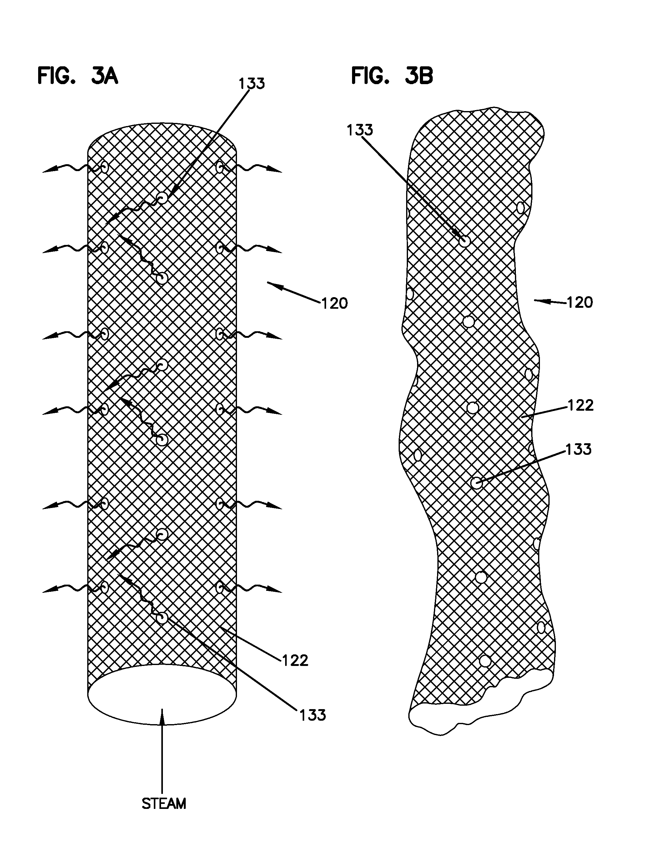
[0031] FIG. 3A is a close-up perspective view of another embodiment of a steam dispersion tube configured for use with the system shown in FIGS. 1A-1B, the tube shown in an inflated configuration, wherein the material of the tube is impermeable to steam but includes a plurality of apertures for exiting the steam therefrom;
[0032] FIG. 3B illustrates the steam dispersion tube of FIG. 3A in a deflated configuration;
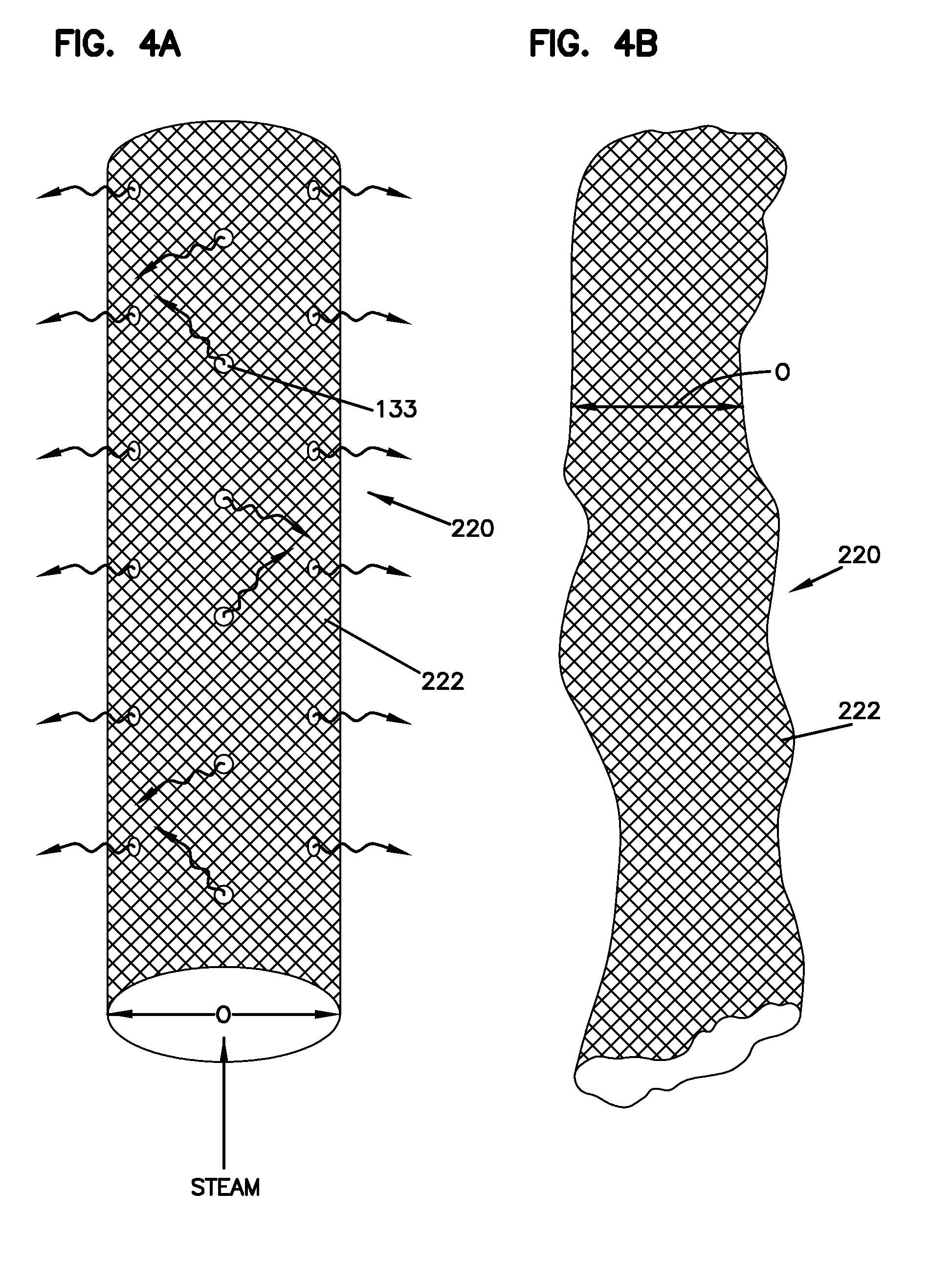
[0033] FIG. 4A is a close-up perspective view of yet another embodiment of a steam dispersion tube configured for use with the system shown in FIGS. 1A-1B, the tube shown in an inflated configuration, wherein the material of the tube is permeable to steam and also includes a plurality of apertures for exiting the steam therefrom;
[0034] FIG. 4B illustrates the steam dispersion tube of FIG. 4A in a deflated configuration;
[0035] FIG. 5A is a close-up perspective view of one of the apertures shown in FIGS. 3A, 3B, 4A, wherein the apertures can change in cross-dimensional size in response to steam pressure, the aperture shown in a higher-pressure condition;
[0036] FIG. 5B illustrates the aperture of FIG. 5A in a lower-pressure condition;
[0037] FIG. 6 is a perspective view of a reinforcing support structure that may be used to support one of the steam dispersion tubes used in the system of FIGS. 1A-1B, wherein the reinforcing support structure is configured to generally maintain the shape of the steam dispersion tube and wherein the reinforcing support structure may be used within the steam dispersion tube or on the exterior of the steam dispersion tube;
[0038] FIG. 7 is a perspective view of yet another steam dispersion tube configured for use with the system shown in FIGS. 1A-1B, wherein the flexible material of the steam dispersion tube is supported with an internally located reinforcing support structure and also includes a wicking material surrounding the tube;
[0039] FIG. 8 is a perspective view of another embodiment of a steam dispersion system having features that are examples of inventive aspects in accordance with the principles of the present disclosure, wherein the steam dispersion system includes a manifold defining a spherical shape having at least a portion comprised of a flexible, fabric, or non-metallic material, wherein the manifold communicates directly with a steam source, the manifold configured to evenly distribute the steam provided from the steam source;
[0040] FIG. 9 is a perspective view of another embodiment of a steam dispersion system having features that are examples of inventive aspects in accordance with the principles of the present disclosure, wherein the steam dispersion system includes a manifold defining a cylindrical ring shape having at least a portion comprised of flexible, fabric, or non-metallic material, wherein the manifold communicates directly with a steam source, the manifold configured to evenly distribute the steam provided from the steam source; and
[0041] FIG. 10 is a perspective view of another embodiment of a steam dispersion system having features that are examples of inventive aspects in accordance with the principles of the present disclosure, wherein the steam dispersion system includes a manifold defining a tubular shape having at least a portion comprised of flexible, fabric, or non-metallic material, wherein the manifold communicates directly with a steam source and does not include a steam dispersion tube extending therefrom, the manifold configured to evenly distribute the steam provided from the steam source.
DETAILED DESCRIPTION
[0042] The principles disclosed herein relate to steam dispersion systems that utilize flexible materials in the construction of steam dispersion components such as tubes, headers, and frames. According to one particular aspect, the materials from which the steam dispersion components are constructed may be non-metallic materials such as polymeric materials. According to another particular aspect, the materials from which the steam dispersion components are constructed may be fabric materials. According to one particular aspect, the materials may include woven or non-woven materials. If formed from fabric materials, the fabric materials may be woven or non-woven fabric materials. Fabrics may include materials that are produced by knitting, weaving, or felting of fibers. Fabrics may include materials that are non-woven fabrics or fabric-like materials made from long fibers, bonded together by chemical, mechanical, heat or solvent treatment. Fabric materials may include materials such as felt, which is neither woven nor knitted.
[0043] For example, using a fabric material, such as polyester, in place of steel to construct a portion of a steam dispersion system presents many advantages. For example, polyester fabric is not as thermally conductive as steel. As a result, less condensate may form and less heat will be lost to air. In fact, testing has shown that polyester fabric dispersion tubes produce less condensate and heat gain than steel tubes and even less than steel tubes that have been insulated with materials such as polyvinylidene fluoride fluoropolymer ("PVDF"). Furthermore, as steam enters a fabric steam dispersion system, a portion of the steam that condenses will wet the fabric and wick into it. The remainder of the steam exits through the pores of the fabric membrane. The condensate that has wicked into the fabric will eventually evaporate into the air. Since the fabric membrane is uniformly permeable to air, the steam can exit evenly and with more contact than what a limited quantity perforation can provide. Thus, a fabric steam dispersion system may not only be more energy efficient than a steel constructed component (due to a reduction in condensate and heat loss) but the permeable fabric membrane is likely to result in shorter absorption distances. Testing has shown that the spaces between the fibers in the fabric essentially function as hundreds or thousands of apertures per square inch of fabric for dispersion of steam.
[0044] There are additional advantages that fabric or flexible materials present when compared to conventional rigid stainless steel steam dispersion systems. The rigidity of steel results in a system whereby static air pressure drops across the dispersion tube. This necessitates the need for constant fan horsepower, even when not humidifying. In contrast, the fabric material may be flexible and may provide the ability to collapse or deflate the component when steam pressure drops, reducing the system's obstruction to airflow and thus reducing the fan horsepower.
[0045] Furthermore, materials such as fabric materials can be manufactured into various shapes outside of the conventional, cylindrical tubes that are formed by conventional manufacturing techniques. Fabric materials can be manufactured into shapes that optimize steam dispersion as will be described in further detail below. Thus, a fabric based steam dispersion system can optimize steam dispersion while also minimizing static air pressure drops.
[0046] Furthermore, materials such as fabric materials may be much more cost efficient alternative to metals such as stainless steel generally costing only a fraction of the price. Additionally, fabric materials generally weigh much less and can be collapsed, folded, or rolled to minimize size and volume of the overall component. This allows for convenient storing, handling, and shipping. Installation costs may also potentially be reduced. In sharp contrast, rigid metal based components such as stainless steel tubes, headers, and frames may be more expensive and difficult to store, handle, and transport because of their weight and size.
[0047] It should be noted that even though non-metallic materials may provide certain advantages as noted above, the inventive aspects of the disclosure are fully applicable to metallic materials. Certain metallic materials such as metallic fabrics or fabrics that include metallic components or fibers may provide the advantages discussed above with respect to the inventive aspects of the steam dispersion systems discussed herein. Metallic materials that may provide the flexibility, the permeability, or the lack of thermal conductivity desired for the steam dispersion systems of the present disclosure are certainly contemplated.
[0048] An embodiment of a steam dispersion system 10 having features that are examples of inventive aspects in accordance with the principles of the present disclosure is illustrated in FIGS. 1A-1B.
[0049] In the depicted embodiment, the steam dispersion system 10 includes a steam dispersion apparatus 12 configured to receive humidification steam from a steam source 14. The steam dispersion apparatus 12 shown includes a plurality of steam dispersion tubes 20 extending from a steam manifold 18. In the embodiment shown, the steam dispersion apparatus 12 includes three steam dispersion tubes 20 extending out of the manifold 18, wherein at least portions of the steam dispersion tubes 20 comprise of a flexible material 22 as discussed above. The steam dispersion tubes 20 extend between the manifold 18 and a bracket 24 that may be used to mount the tubes 20 in a duct 26. The manifold 18, along with the bracket 24, may define a frame 28 of the steam dispersion system 10. It should be noted that the steam dispersion tubes 20 may be mounted to the air duct 26 in other various ways.
[0050] The steam source 14 may be a boiler or another steam source such as an electric or gas humidifier. The steam source 14 provides pressurized steam towards the manifold 18 of the steam dispersion apparatus 12. In the depicted example, each of the tubes 20 communicates with the manifold 18 for receiving pressurized steam. The steam tubes 20, in turn, disperse the steam to the atmosphere at atmospheric pressure. In the embodiment illustrated in FIGS. 1A-1B, the manifold 18 is depicted as a header 30, which is a manifold designed to distribute pressure evenly among the tubes protruding therefrom.
[0051] In a system such as that illustrated in FIGS. 1A-1B, the steam supplied by the steam source 14 is piped through the system 10 at a pressure generally higher than atmospheric pressure, which is normally the pressure at the point where the steam exits the header 30 and meets duct air. The pressure created by the flowing steam within the tubes 20 causes the steam dispersion tubes 20 to inflate and take a tubular shape, as illustrated in the examples depicted in FIGS. 1A, 2A, 3A, and 4A.
[0052] If the flexible material is a fabric material or a fiber-based material, the steam can exit the steam dispersion tubes 20 through tiny pores 32 defined between the fibers of the material 22, as illustrated in FIG. 2A.
[0053] When the flow of steam is ceased, leading to reduced pressure inside the tubes 20, the material 22 of the tubes 20 is configured to deflate/collapse. Thus, the flexible portions of the tubes 20 are configured as collapsible structures wherein the outer dimension O thereof can change from a greater, higher-pressure, size, to a smaller, lower-pressure, size. FIG. 1B illustrate the tubes 20 in a collapsed condition.
[0054] Now referring to FIGS. 2A-2B, a close-up perspective view of one of the steam dispersion tubes 20 in FIG. 1A is illustrated. In FIG. 2A, the steam dispersion tube 20 is illustrated in an inflated configuration and in FIG. 2B, the tube 20 is shown in a deflated configuration. The version of the tube 20 illustrated in FIGS. 2A-2B is permeable to steam. In the depicted embodiment, the flexible material is a fabric material that defines pores 32 between the fibers making up the fabric material 22.
[0055] FIGS. 3A-3B illustrate a close-up perspective view of yet another steam dispersion tube 120 usable with the system 10 illustrated in FIGS. 1A-1B, wherein the material 122 of the tube is impermeable to steam. The tube 120 includes a plurality of apertures 133 formed in the material 122 for exiting the steam. In this manner, the tube 120 still provides the advantage of collapsibility when the pressure is reduced.
[0056] FIGS. 4A-4B illustrate a close-up perspective view of yet another steam dispersion tube 220 usable with the system 10 illustrated in FIGS. 1A and 1B, wherein the material 222 of the tube is permeable to steam and also includes a plurality of apertures 133 similar to the version of the tube 120 shown in FIGS. 3A-3B. Similar to the tubes 20, 120 shown in FIGS. 2A, 2B, 3A, and 3B, the tube 220 shown in FIGS. 4A-4B is collapsible for changing the outer dimension O of the portion of the tube 220 comprised of the material 222 from a greater, higher-pressure, size, to a smaller, lower-pressure, size.
[0057] FIGS. 5A and 5B illustrate close-up perspective views of one of the apertures 133 in FIGS. 3A, 3B, 4A, wherein the apertures 133 are configured to change in cross-dimensional size in response to steam pressure. In FIG. 5A, the aperture 133 is shown in a higher-pressure condition and FIG. 5B illustrates the aperture 133 in a lower-pressure condition. The variability of the cross-dimensional size of the apertures 133 may accommodate a larger range of steam loads.
[0058] In certain embodiments, it might be useful to provide rigidity for the portions of the steam dispersion system 10 that are comprised of flexible materials and not allow for collapsibility. FIG. 6 is a perspective view of a reinforcing support structure 34 that may be used to support one of the steam dispersion tubes 20, 120, 220 used in the system 10 of FIGS. 1A-1B, wherein the reinforcing support structure 34 is configured to generally maintain the shape of the flexible steam dispersion tube and wherein the reinforcing support structure 34 may be used within the steam dispersion tube or on the exterior of the steam dispersion tube. In the version illustrated in FIG. 6, the reinforcing support structure 34 is defined by a metallic mesh 36 having a generally open skeletal structure so as to not interfere with the steam dispersion properties of the flexible material. The metallic mesh 36 may be a structure that is removable from the flexible portion of the steam dispersion tube 20, 120, 220. In this manner, the flexible material may still be collapsible for storage or transport reasons and the mesh 36 provided during the mounting of the flexible portion to an air duct 26.
[0059] As noted above, in certain embodiments, the portion of the steam dispersion system comprised of the non-metallic material such as the steam dispersion tube 20, 120, 220 may surround the reinforcement support structure 34. In other embodiments, the reinforcing support structure 34 may surround the portion of the steam dispersion tube comprised of the flexible material. For example, in a steam dispersion tube 20, 120, 220 that defines an inner face 38 and an outer face 40 wherein the steam flows from the inner face 38 toward the outer face 40, the reinforcing support structure 34 may surround the outer face 40.
[0060] It should be understood that in yet other embodiments wherein rigidity of the steam dispersion structures is desired, the fabric or non-metallic material of the dispersion system 10 may be rigid enough itself to define the reinforcing support structure and may retain its shape even during a low-pressure condition. Such materials may still be collapsible under a load for storage and transport reasons. However, they may be designed to retain their shape when mounted in an HVAC environment such as an air duct 26 and under operating pressures.
[0061] FIG. 7 illustrates another embodiment of a steam dispersion tube 320 configured for use with the system 10 shown in FIGS. 1A-1B. In the version in FIG. 7, the material 322 of the steam dispersion tube is supported with an internally located reinforcing support structure 34 and also includes a wicking material 42 surrounding portion 322 of the tube 320. As noted above, as steam enters the steam dispersion system, a portion of the steam that condenses will tend to wet the non-metallic material 322 and wick into it. The remainder of the steam exits through the pores 332 of the membrane 322. The condensate that has wicked into the material 322 will eventually evaporate into the air. The wicking material 42 surrounding material 322 facilitates this process. An example of a wicking material 43 could be swamp cooler media.
[0062] Referring now to FIGS. 8-10, although in the previous examples of steam dispersion systems 10, only the steam dispersion tubes 20, 120, 220, 320 of the system 10 are shown to be comprised of flexible, fabric, or non-metallic materials, in other embodiments, such materials can be used to construct essentially the entire steam dispersion system. For example, according to certain embodiments, a manifold that communicates directly with the steam source, such as a header, may be constructed from a flexible, a fabric (e.g., non-metallic or metallic), or a non-metallic material wherein steam dispersion would occur through the material without the need for additional tubes extending from the header. According to certain embodiments, a majority of the manifold may be comprised of such a material.
[0063] The material that may be used on any portion of a steam carrying apparatus or system may be permeable to steam (with or without additional apertures larger than those defined by fibers of a fabric if the material is a fibrous material) or impermeable to steam with additional apertures.
[0064] And, although in the FIG. 7, a wicking type material 42 has been shown to be used only on a steam dispersion tube, the wicking material 42 can be included on other portions of the steam dispersion system, such as the header. The wicking material 42 can be provided on any portion of any steam carrying apparatus or system.
[0065] FIG. 8 is a perspective view of an embodiment of a steam dispersion system 410 having features that are examples of inventive aspects in accordance with the principles of the present disclosure, wherein the steam dispersion system 410 includes a manifold 418 defining a spherical shape having at least a portion comprised of a fabric (e.g., non-metallic or metallic), a flexible, or a non-metallic material 422, wherein the manifold 418 communicates directly with a steam source 414. The spherical shape of the manifold 418 is configured to evenly distribute the steam provided from the steam source 414. In the example embodiment, the spherical shaped manifold may be attached to the air duct 26 via cables 50. Other attachment methods are possible.
[0066] FIG. 9 is a perspective view of another embodiment of a steam dispersion system 510 having features that are examples of inventive aspects in accordance with the principles of the present disclosure, wherein the steam dispersion system 510 includes a manifold 518 defining a cylindrical ring shape having at least a portion comprised of a material 522 similar to material 422 discussed above. The ring shape of the manifold 518 is configured to evenly distribute the steam provided from the steam source 514. The ring shaped manifold 518 can also be attached to the air duct 26 via cables 50.
[0067] FIG. 10 is a perspective view of another embodiment of a steam dispersion system 610 having features that are examples of inventive aspects in accordance with the principles of the present disclosure, wherein the steam dispersion system 610 includes a conventional tubular type manifold design 618 extending across the air duct 26. However, in the embodiment shown in FIG. 10, unlike a conventional header that might extend across an air duct 26 and support a plurality of tubes, the manifold 618 does not include a steam dispersion tube extending therefrom and is comprised of a material 622 similar to materials 422, 522 to evenly distribute the steam provided from the steam source 614. The tubular manifold 618 may extend horizontally or vertically within the air duct 26 and may be attached to the walls of the air duct 26 via various means known in the art.
[0068] It should be noted that the portions of the steam dispersion systems supplying steam to the manifolds of the illustrated systems may include one or more steam sources. For example, the humidification steam supplied to the manifolds may be generated by a boiler or an electric or gas humidifier which operates under low pressure (e.g., less than 1 psi.). In other embodiments, the humidification steam supplied to the manifolds may be operated at higher pressures, such as between about 2 psi and 60 psi. In other embodiments, the humidification steam source may be run at higher than 60 psi. As noted above, the humidification steam that is inside the manifold is normally at about atmospheric pressure at the point the steam is exposed to the duct air.
[0069] The above specification, examples and data provide a complete description of the inventive features of the disclosure. Many embodiments of the disclosure can be made without departing from the spirit and scope thereof.
* * * * *
D00000
D00001
D00002
D00003
D00004
D00005
D00006
D00007
D00008
D00009
D00010
XML
uspto.report is an independent third-party trademark research tool that is not affiliated, endorsed, or sponsored by the United States Patent and Trademark Office (USPTO) or any other governmental organization. The information provided by uspto.report is based on publicly available data at the time of writing and is intended for informational purposes only.
While we strive to provide accurate and up-to-date information, we do not guarantee the accuracy, completeness, reliability, or suitability of the information displayed on this site. The use of this site is at your own risk. Any reliance you place on such information is therefore strictly at your own risk.
All official trademark data, including owner information, should be verified by visiting the official USPTO website at www.uspto.gov. This site is not intended to replace professional legal advice and should not be used as a substitute for consulting with a legal professional who is knowledgeable about trademark law.