Linear Actuator System
Jordan; Jeffrey Scott
U.S. patent application number 16/373601 was filed with the patent office on 2019-10-03 for linear actuator system. The applicant listed for this patent is Wolf Tooth Components, LLC. Invention is credited to Jeffrey Scott Jordan.
| Application Number | 20190301497 16/373601 |
| Document ID | / |
| Family ID | 68055940 |
| Filed Date | 2019-10-03 |


View All Diagrams
| United States Patent Application | 20190301497 |
| Kind Code | A1 |
| Jordan; Jeffrey Scott | October 3, 2019 |
LINEAR ACTUATOR SYSTEM
Abstract
A linear actuator system includes a linear actuator including an outer body, an inner body disposed within the outer body, a fluid chamber at least partially extending between the inner body and the outer body, a piston chamber extending at least partially within the inner body, a valve configured to selectively fluidly couple the fluid chamber and the piston chamber to each other, a piston assembly including a piston, a variable volume within the piston chamber that extends between the piston and the valve, and a gas collector assembly including a fluid passageway. The piston assembly is disposed within the piston chamber, wherein a movement of the piston assembly causes a gas separated from a liquid within the variable volume to flow through the fluid passageway, through the valve, and into the fluid chamber.
| Inventors: | Jordan; Jeffrey Scott; (Fishers, IN) | ||||||||||
| Applicant: |
|
||||||||||
|---|---|---|---|---|---|---|---|---|---|---|---|
| Family ID: | 68055940 | ||||||||||
| Appl. No.: | 16/373601 | ||||||||||
| Filed: | April 2, 2019 |
Related U.S. Patent Documents
| Application Number | Filing Date | Patent Number | ||
|---|---|---|---|---|
| 62651379 | Apr 2, 2018 | |||
| Current U.S. Class: | 1/1 |
| Current CPC Class: | F15B 21/044 20130101; F15B 2211/7057 20130101; F15B 2211/72 20130101; B62K 19/36 20130101; F15B 2201/305 20130101; F15B 2211/7055 20130101; F15B 15/16 20130101; F16B 2/065 20130101; B62J 2001/085 20130101; F15B 15/227 20130101; F15B 11/072 20130101; F15B 15/202 20130101; B62J 1/08 20130101; F15B 15/26 20130101; F15B 15/1476 20130101 |
| International Class: | F15B 21/044 20060101 F15B021/044; B62J 1/08 20060101 B62J001/08; F15B 15/16 20060101 F15B015/16 |
Claims
1. A linear actuator system, comprising: a linear actuator, the linear actuator comprising: an outer body; an inner body disposed within the outer body; a fluid chamber at least partially extending between the inner body and the outer body; a piston chamber extending at least partially within the inner body; a valve configured to selectively fluidly couple the fluid chamber and the piston chamber to each other; a piston assembly comprising a piston, the piston assembly disposed within the piston chamber; a variable volume within the piston chamber that extends between the piston and the valve; and a gas collector assembly including a fluid passageway; wherein a movement of the piston assembly causes a gas separated from a liquid within the variable volume to flow through the fluid passageway, through the valve, and into the fluid chamber.
2. The linear actuator system of claim 1, wherein the gas collector assembly comprises a needle extending from the piston assembly generally towards the valve, the needle defining at least a portion of the fluid passageway.
3. The linear actuator system of claim 2, wherein a movement of the piston assembly generally towards the valve causes at least a portion of the needle to be received within a receptacle.
4. The linear actuator system of claim 1, wherein the gas collector assembly comprises a receptacle formed within the piston assembly, the receptacle defining at least a portion of the fluid passageway.
5. The linear actuator system of claim 4, wherein the piston assembly comprises the piston and a receptacle body coupled to the piston, the receptacle body defining, at least in part, the receptacle.
6. The linear actuator system of claim 4, wherein the piston defines, at least in part, the receptacle.
7. The linear actuator system of claim 4, wherein a movement of the piston assembly generally towards the valve causes the receptacle to receive at least a portion of a needle.
8. The linear actuator system of claim 1, wherein the gas collector assembly comprises a needle that extends from an end region of the piston chamber and generally towards the piston assembly, the needle defining at least a portion of the fluid passageway.
9. The linear actuator system of claim 8, wherein a movement of the piston assembly generally towards the needle causes at least a portion of the needle to be received within a receptacle.
10. The linear actuator system of claim 1, wherein the gas collector assembly comprises a receptacle for receiving at least a portion of a needle, the receptacle defining at least a portion of the fluid passageway.
11. The linear actuator system of claim 10, wherein the receptacle and the valve are monolithic.
12. The linear actuator system of claim 10, wherein the receptacle and the piston are monolithic.
13. The linear actuator system of claim 1, wherein the gas collector assembly further comprises a funnel, the funnel urging gas separated from a liquid towards an inlet of the fluid passageway.
14. The linear actuator system of claim 13, wherein the gas collector assembly further comprises a needle, the needle defining at least a portion of the fluid passageway.
15. The linear actuator system of claim 13, wherein the gas collector assembly further comprises a receptacle for receiving at least a portion of a needle, the needle defining at least a portion of the fluid passageway.
16. The linear actuator system of claim 1, wherein the valve is an inverse spool valve.
17. The linear actuator system of claim 16, wherein the inverse spool valve comprises: a core, the core including at least one fluid channel having a piston chamber port and a fluid chamber port; and a sleeve, the sleeve extending around at least a portion of a periphery of the core and being movable between an open and a closed position, wherein when the sleeve is in the open position, a fluid path extends from the variable volume, through the fluid channel, and into the fluid chamber; and when the sleeve is in the closed position, the variable volume is sealed from the fluid chamber.
18. The linear actuator system of claim 17, wherein the inverse spool valve is configured such that fluid pressure acting on the inverse spool valve does not substantially bias the sleeve towards the open position or the closed position.
19. The linear actuator system of claim 17, wherein the inverse spool valve further comprises a biasing mechanism to bias the sleeve towards the open or closed position.
20. The linear actuator system of claim 19, wherein the biasing mechanism is a spring.
21. The linear actuator system of claim 19, wherein the biasing mechanism is configured to urge the sleeve towards the open or the closed position using fluid pressure.
22. The linear actuator system of claim 17, wherein the sleeve includes a sleeve extension, the sleeve extension comprising a first end and a second end disposed opposite the first end, the first end disposed within the outer body and the second end configured to be disposed external to the outer body.
23. The linear actuator system of claim 22, wherein the inverse spool valve further comprises a first chamber seal, a second chamber seal, and an environment seal, the first and second chamber seals being disposed on opposing sides of the fluid chamber port of the fluid channel and the environment seal being disposed between the sleeve extension and the outer body.
24. The linear actuator system of claim 23, wherein the inverse spool valve further comprises a backup seal and, wherein, a separation volume is defined between the backup seal, the second chamber seal, the sleeve, and the core.
25. The linear actuator system of claim 24, wherein the inverse spool valve further comprises a spool valve port extending through the sleeve, the spool valve port fluidly coupling the separation volume to the fluid chamber.
26. The linear actuator system of claim 22, wherein the sleeve extension defines a cavity extending from the second end towards the first end, wherein the second end is an open end.
27. The linear actuator system of claim 26, wherein the sleeve includes a connector for receiving a control cable, the control cable being configured to exert a force on the connector and urge the sleeve toward the open or the closed position.
28. The linear actuator system of claim 27, wherein the connector and the sleeve are monolithic.
29. The linear actuator system of claim 28, further comprising the control cable, the control cable including a head and the connector includes a pocket for receiving the head of the control cable, wherein the head of the control cable is retained in the pocket in response to a tension being applied to the control cable.
30. The linear actuator system of claim 1, further comprising a dropper seat post.
Description
CROSS-REFERENCE TO RELATED APPLICATIONS
[0001] This application claims priority under 35 U.S.C. .sctn. 119(e) to U.S. Provisional Patent Application Ser. No. 62/651,379 filed on Apr. 2, 2018, and incorporated herein by reference.
TECHNICAL FIELD
[0002] This instant specification relates to telescopic linear actuators with self-bleeding hydraulics. This instant specification relates to a balanced, direct-actuation, spool-type flow control valve used in a linear actuator.
BACKGROUND
[0003] Pneumo-hydraulic linear actuators rely on gas and liquids to operate. The liquid is generally used to provide an incompressible column of fluid in which to support a load. The gas is generally used to provide a bias force which can be used to automatically extend (or retract) the linear actuator. Most pneumo-hydraulic linear actuators utilize an internal floating piston (IFP) to maintain separation of the gas from the liquid in a reservoir that contains both liquid and gas.
[0004] These types of linear actuators suffer when gas unintentionally enters the fluid column. The liquid commonly used in these linear actuators, in itself, can be considered relatively incompressible, however when gas is mixed with the liquid, the fluid becomes compressible. This result is usually undesirable, especially when the linear actuator's purpose is to securely maintain position. Gas can enter the fluid column by a variety of means; most commonly by leaking seals either in the IFP or in the piston seal. Leaking seals is virtually unavoidable, especially with wear of the system over time. Therefore, the fluid column should eventually be purged of the gas. This is typically done by disassembly of the system, manually bleeding the gas through a bleed port, or manually opening a secondary valve specific to bleeding gas from the column. Because of this, many manufacturers seek to minimize leakage of gas into the fluid column in order to extend the service life. However, eventually the system will need to be bled. This type of service is disruptive, causes downtime of equipment, and can be expensive.
[0005] Most hydraulic seatposts utilize a poppet valve. Poppet valves are affected by the pressure acting upon them. System pressures can also act upon the poppet to move them. If a poppet is configured to open into (to the inside) a high-pressure cylinder, the pressure of the cylinder will help hold the valve closed. If the pressure increases significantly, the force required to open the valve also increases. In some cases, this force can become too high and the valve cannot be easily opened. A rider applying body weight to a seatpost is enough to make a poppet valve difficult to open. Many times, the rider first removes his/her weight from the saddle and then actuates it. This extra step can disrupt the riding position and balance of the bike.
[0006] However, if the poppet is configured to open away (to the outside) from the cylinder, the pressure in the cylinder will act upon the poppet to open it. To keep the valve closed in this configuration a spring bias is used. The spring should be strong enough to overcome the force applied by the pressure inside the cylinder. However, if this force is great enough, the ability to actuate the valve by hand becomes too difficult.
[0007] In either case, the direct effect of the pressure on the valve changes the actuation force required to operate the actuator. This variable force is undesirable.
[0008] Also, most hydraulic seatposts up until this point have used a "push" force to open the valve. For seatposts that are cable controlled, this force is converted to a pull motion. A variety of means to achieve this have been developed by various manufacturers, but most commonly a lever or cam device to convert pull to push is invoked. Other solutions may utilize hydraulic means of converting pull to push.
SUMMARY
[0009] In general, this document describes telescopic linear actuators. Namely, linear actuators that automatically and continuously bleeds itself--maintaining an incompressible fluid column and extending the service life of the linear actuator.
[0010] The systems and techniques described here may provide one or more of the following advantages. First, the system provides a way for gas to be automatically purged from the fluid column. Second, the system eliminates the need for an IFP. Third, the purge architecture has no extra moving parts. Fourth, the simple design provides for significant weight savings. Fifth, the purge system can be incorporated into various linear actuator architectures.
[0011] In general, this document describes a balanced (e.g., remains substantially unaffected by pressure changes in the actuator), direct-actuation, inverse spool-type flow control valve. An inverse spool-type control valve includes an outside that moves relative to an inside, as described herein the outside may generally be referred to as an "actuator" and the inside may generally be referred to as a "core." In a non-inverse spool-type control valve the core/spool (inside component) is what moves.
[0012] The systems and techniques described here may provide one or more of the following advantages. First, low actuation force. Second, pressure balanced valve with little to no pressure bias on the actuator. Third, direct pull actuation. Fourth, simple control cable attachment/detachment. Fifth, flow modulation. Sixth, alternate unbalanced configuration that produces a bias force in place of the spring.
[0013] The details of one or more implementations are set forth in the accompanying drawings and the description below. Other features and advantages will be apparent from the description and drawings
BRIEF DESCRIPTION OF THE DRAWINGS
[0014] FIG. 1 illustrates a section view of an example of a linear actuator in accordance with the present disclosure including a detailed component overview, with the linear actuator fully extended, locked.
[0015] FIGS. 2A, 2B, 2C, 2D illustrate section views of examples of four embodiments of a linear actuator in accordance with the present disclosure, respectively, with the linear actuators fully extended, locked (gas and liquid shown).
[0016] FIGS. 3A, 3B, 3C, 3D illustrate section views of the examples of the four embodiments of the linear actuators of FIGS. 2A, 2B, 2C, 2D, respectively, with the linear actuators fully compressed, locked (gas and liquid shown).
[0017] FIGS. 4A, 4B illustrate an example of a linear actuator in accordance with the present disclosure including illustrations of Volume A and Volume B using the first embodiment of the linear actuator of FIGS. 2A, 3A, with FIG. 4A illustrating the linear actuator fully extended, and FIG. 4B illustrating the linear actuator fully retracted.
[0018] FIGS. 5A, 5B, 5C, 5D, 5E, 5F, 5G illustrate an example of a first embodiment of a linear actuator in accordance with the present disclosure illustrating compression flow with gas purge.
[0019] FIGS. 6A, 6B, 6C, 6D, 6E, 6F illustrate an example of the first embodiment of a linear actuator in accordance with the present disclosure illustrating extension flow after gas purge.
[0020] FIGS. 7A, 7B, 7C, 7D, 7E, 7F, 7G illustrate an example of a second embodiment of a linear actuator in accordance with the present disclosure illustrating compression flow with gas purge.
[0021] FIGS. 8A, 8B, 8C, 8D, 8E, 8F illustrate an example of the second embodiment of a linear actuator in accordance with the present disclosure illustrating extension flow after gas purge.
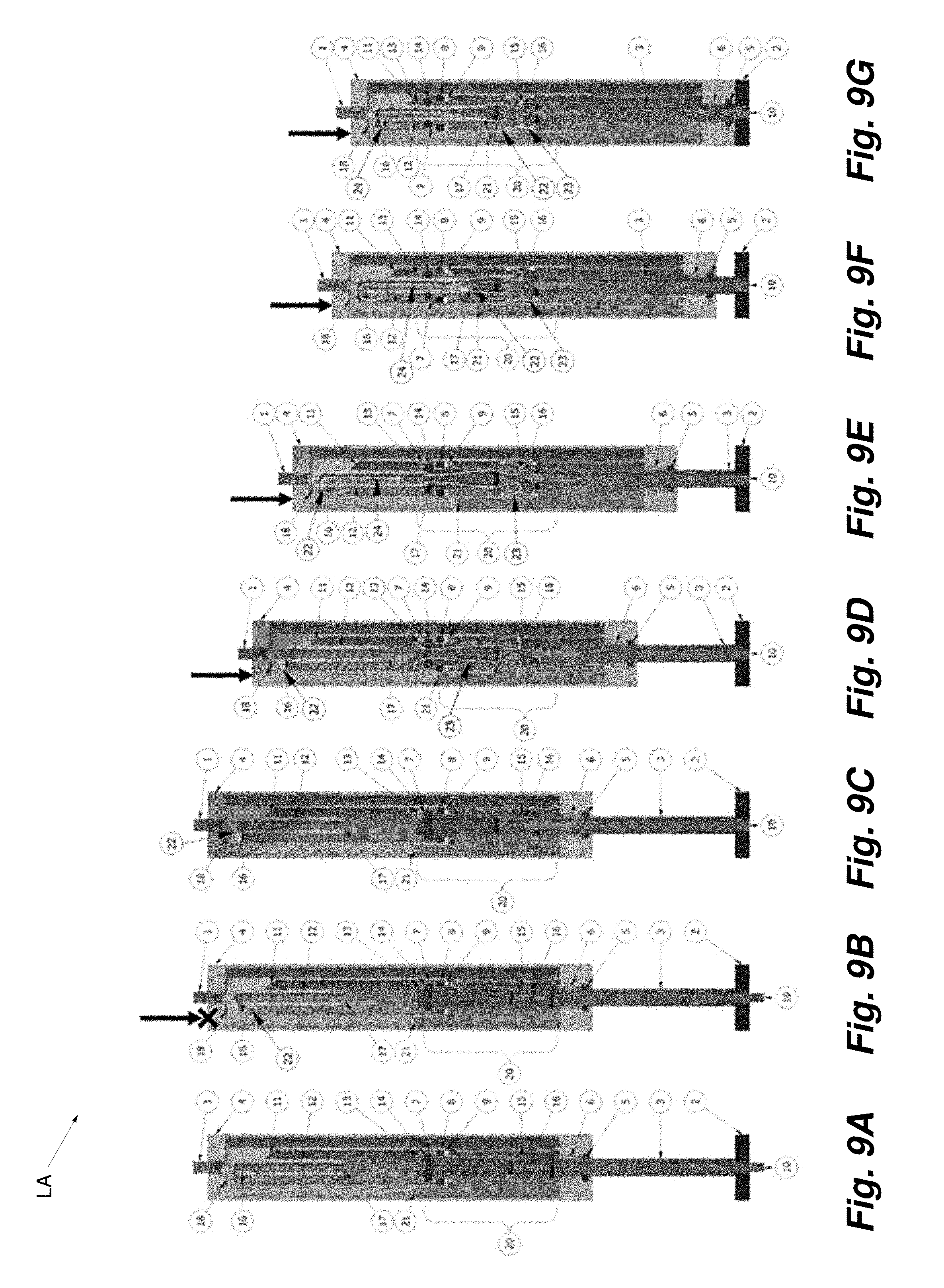
[0022] FIGS. 9A, 9B, 9C, 9D, 9E, 9F, 9G illustrate an example of a third embodiment of a linear actuator in accordance with the present disclosure illustrating compression flow with gas purge.
[0023] FIGS. 10A, 10B, 10C, 10D, 10E, 10F illustrate an example of the third embodiment of a linear actuator in accordance with the present disclosure illustrating extension flow after gas purge.
[0024] FIGS. 11A, 11B, 11C, 11D, 11E, 11F, 11G illustrate an example of a fourth embodiment of a linear actuator in accordance with the present disclosure illustrating compression flow with gas purge.
[0025] FIGS. 12A, 12B, 12C, 12D, 12E, 12F illustrate an example of the fourth embodiment of a linear actuator in accordance with the present disclosure illustrating extension flow after gas purge.
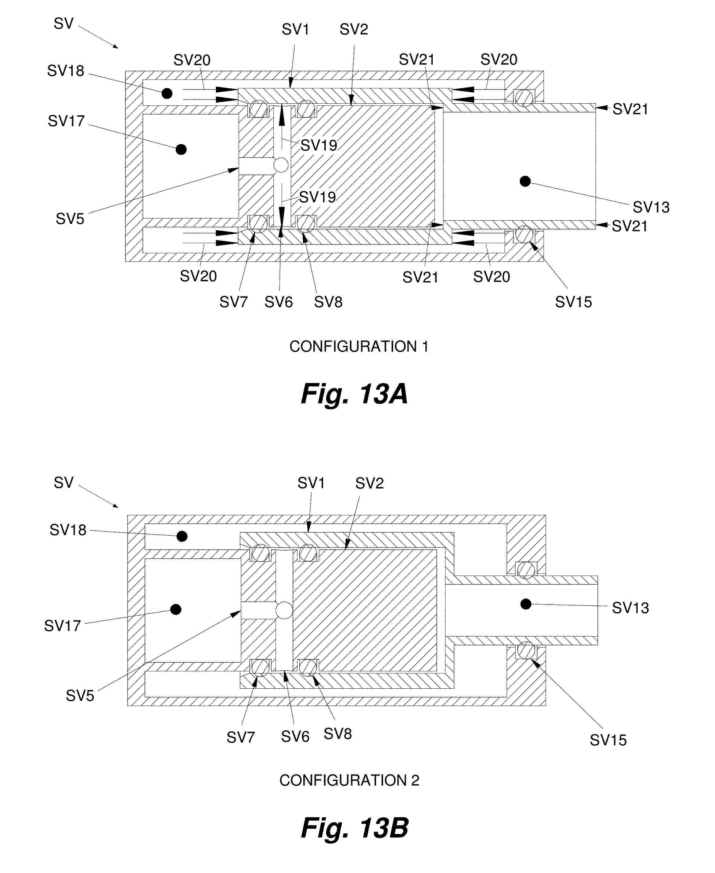
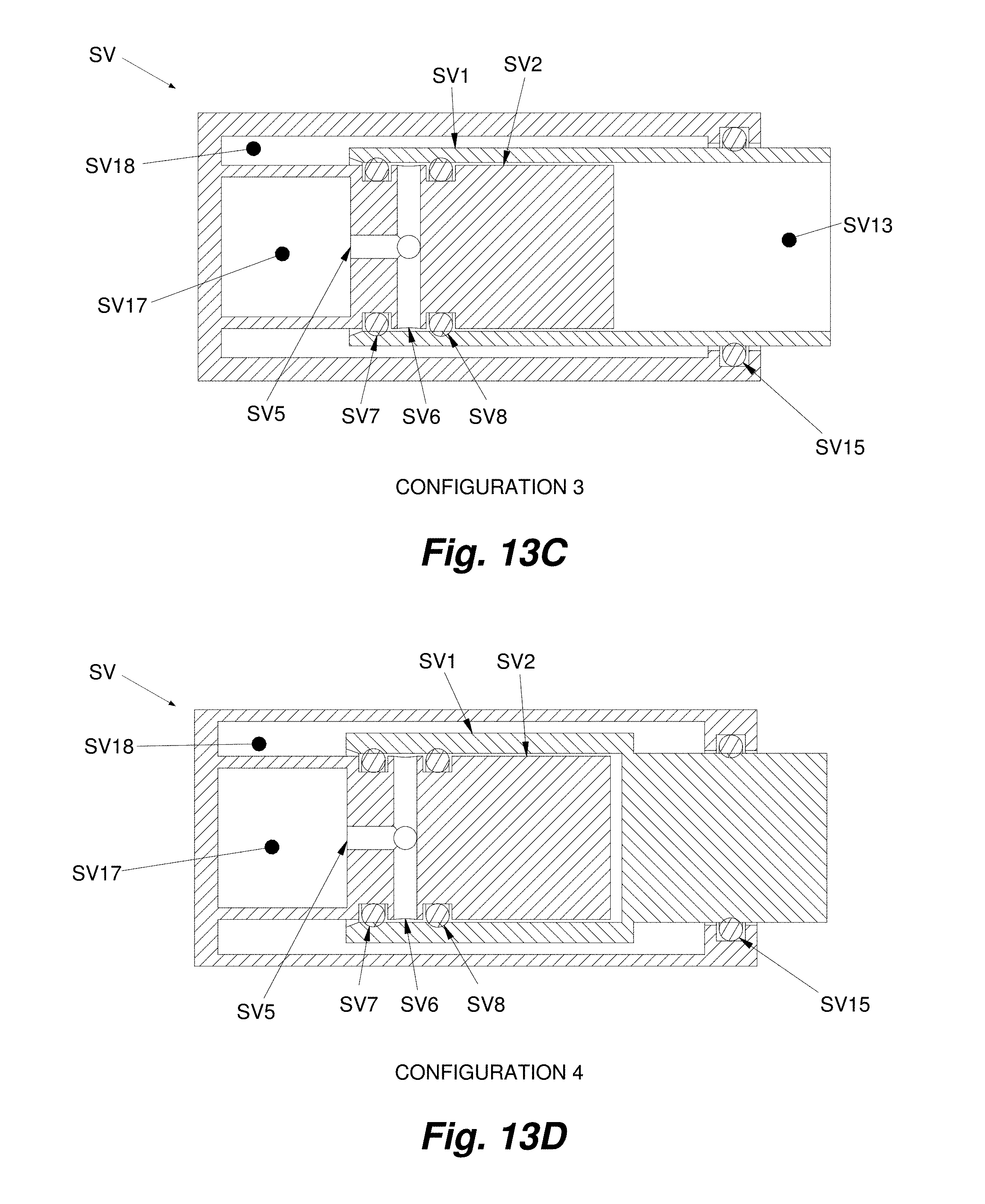
[0026] FIGS. 13A, 13B, 13C, 13D, 13E illustrate section views of examples of five configurations of a spool valve in accordance with the present disclosure, with the configuration of FIG. 13A (Configuration 1) being balanced, the configuration of FIG. 13B (Configuration 2) being unbalanced with inward bias, the configuration of FIG. 13C (Configuration 3) being unbalanced with outward bias, the configuration of FIG. 13D (Configuration 4) being unbalanced with inward bias, and the configuration of FIG. 13E (Configuration 5) being balanced with seal redundancy.
[0027] FIG. 14 illustrates an example of a balanced, direct-pull, inverse spool valve in accordance with the present disclosure--in situ (installed in a pneumo-hydraulic linear actuator).
[0028] FIG. 15 illustrates an example of a balanced, direct-pull, inverse spool valve in accordance with the present disclosure--in situ (equal cross-sectional areas balance forces at seals, diameters A=B, C=D).
[0029] FIGS. 16A, 16B illustrate an example of a balanced, direct-pull, inverse spool valve in accordance with the present disclosure, with FIG. 16A illustrating the valve in a closed position and FIG. 16B illustrating the valve in an open position, with the valve including a spring bias to the closed position.
[0030] FIG. 17 illustrates views of an example of a linear actuator including a spool valve in accordance with the present disclosure including illustration of cable attachment and a detachment pocket in the actuator.
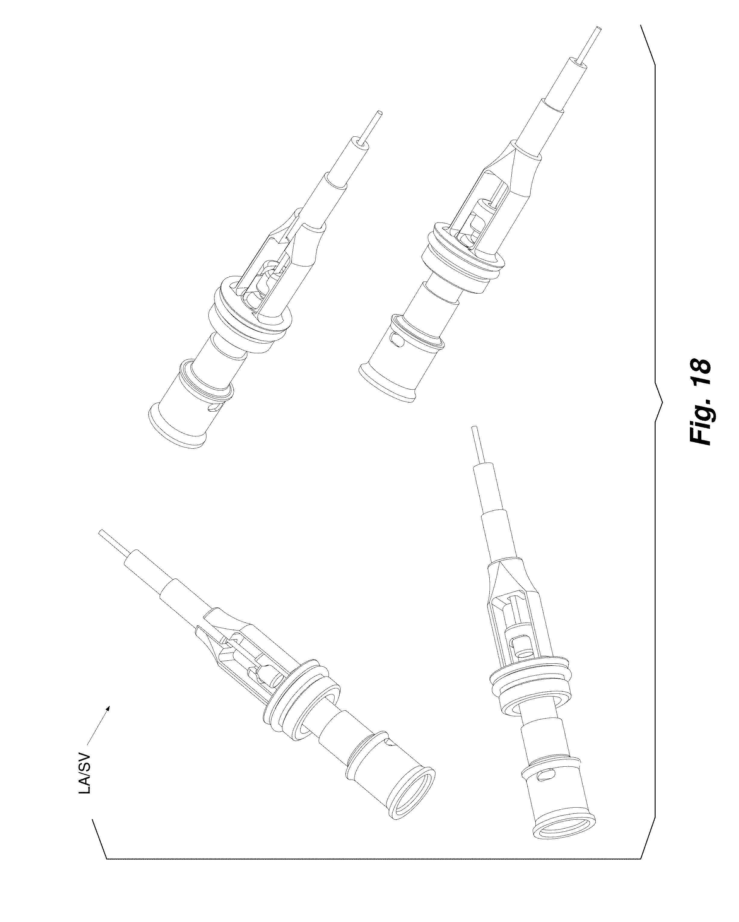
[0031] FIG. 18 illustrates views of an example of a linear actuator including a spool valve in accordance with the present disclosure including illustration of an actuator cable pocket, actuator, housing mount, cable and cable housing.
[0032] FIG. 19 illustrates an example of assembly/disassembly of a cartridge assembly within a shell of a dropper seatpost including an example of a linear actuator in accordance with the present disclosure.
[0033] FIG. 20 illustrates an exploded view of the cartridge assembly of FIG. 19 including an example of a linear actuator in accordance with the present disclosure.
[0034] FIGS. 21A, 21B illustrate section views of an example of a first embodiment of a dropper seatpost including an example of a linear actuator in accordance with the present disclosure.
[0035] FIG. 22 illustrates a section view of an example of a second embodiment of a dropper seatpost including an example of a linear actuator in accordance with the present disclosure.
[0036] FIGS. 23A, 23B illustrate section views of an example of a third embodiment of a dropper seatpost including an example of a linear actuator in accordance with the present disclosure.
[0037] FIG. 24 illustrates a section view of an example of a fourth embodiment of a dropper seatpost including an example of a linear actuator in accordance with the present disclosure.
[0038] FIG. 25 illustrates an example of assembly/disassembly of a cartridge assembly within a shell of the fourth embodiment of a dropper seatpost including an example of a linear actuator in accordance with the present disclosure.
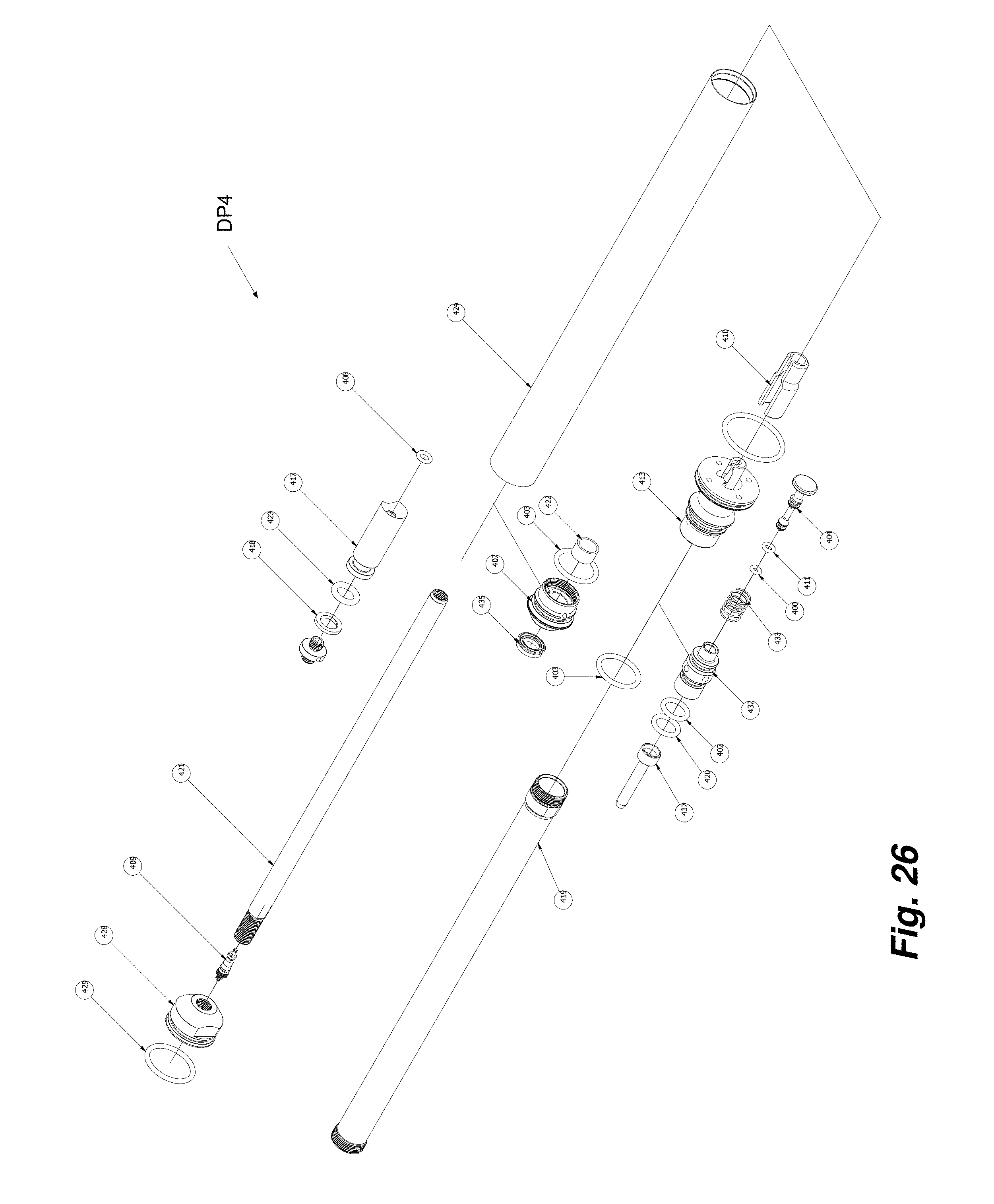
[0039] FIG. 26 illustrates an exploded view of the cartridge assembly of FIG. 25 including an example of a linear actuator in accordance with the present disclosure.
DETAILED DESCRIPTION
[0040] In the following detailed description, reference is made to the accompanying drawings which form a part hereof, and in which is shown by way of illustration specific examples in which the disclosure may be practiced. It is to be understood that other examples may be utilized and structural or logical changes may be made without departing from the scope of the present disclosure.
Telescopic Linear Actuator with Self-Bleeding Hydraulics
[0041] With reference to FIG. 1, FIGS. 2A, 2B, 2C, 2D, FIGS. 3A, 3B, 3C, 3D, FIGS. 4A, 4B, FIGS. 5A, 5B, 5C, 5D, 5E, 5F, 5G, FIGS. 6A, 6B, 6C, 6D, 6E, 6F, FIGS. 7A, 7B, 7C, 7D, 7E, 7F, 7G, FIGS. 8A, 8B, 8C, 8D, 8E, 8F, FIGS. 9A, 9B, 9C, 9D, 9E, 9F, 9G, FIGS. 10A, 10B, 10C, 10D, 10E, 10F, FIGS. 11A, 11B, 11C, 11D, 11E, 11F, 11G, FIGS. 12A, 12B, 12C, 12D, 12E, 12F, examples of a telescopic linear actuator with self-bleeding hydraulics are described. With specific reference to FIG. 15, while there is a step down shown from A/B to C/D, such a configuration may vary. For example, A/B can equal C/D (e.g., A=B=C=D).
Valve
[0042] The configuration of the valve 20 can vary. Two valve types, poppet and spool, are shown in the embodiments but valve types are not limited to only these. The embodiments show a variety of valve 20 configurations, but do not show every type of valve 20 configuration (for example, the fourth embodiment (FIGS. 11A-11G, 12A-12F) can utilize a poppet valve instead of a spool valve, and the third embodiment (FIGS. 9A-9G, 10A-10F) can utilize a spool valve instead of a poppet valve).
[0043] The valve 20 typically can be configured to have at least two positions: opened and closed. In the open configuration, the valve 20 allows fluid to flow through a fluid pathway, the first fluid pathway 23. In the closed configuration, the valve 20 blocks flow through the fluid pathway. The valve 20 can also be partially opened or closed, "throttling" fluid flow. A valve 20 with more than two positions may also be used.
[0044] In most configurations, flow is allowed through the first fluid pathway 23 when the valve actuator 10 is moved in one direction and blocked when the valve actuator 10 returns to the original unactuated position via the valve spring 19.
[0045] The first fluid pathway 23 is a major component of the valve 20 and connects two volumes: Volume A and Volume B. The fluid port in communication with Volume A is the first fluid port 13, the fluid port in communication with Volume B is the second fluid port 15.
Volume A (e.g., a Fluid Column)
[0046] Volume A is known as the "fluid column" and may be filled with only liquid to remain incompressible.
[0047] Volume A is defined in large part by the piston cylinder 25. At one end of the piston cylinder 25 is a movable piston 7 with attached piston rod 3. The piston 7 and piston rod 3 are telescopically allowed to slide within the piston cylinder 25. Located at the other end of the piston cylinder 25 is either a valve 20 (as in the first embodiment (FIGS. 5A-5G, 6A-6F), second embodiment (FIGS. 7A-7G, 8A-8F), and fourth embodiment (FIGS. 11A-11G, 12A-12F)) or capped off (as in the third embodiment (FIGS. 9A-9G, 10A-10F)). If the end of the piston cylinder 25 is capped off, the valve 20 is typically part of the piston 7 (as in the third embodiment (FIGS. 9A-9G, 10A-10F)). These parts (the piston cylinder 25, piston 7, and cylinder cap 27/valve 20) enclose Volume A.
[0048] Since the piston 7 can telescopically slide within the piston cylinder 25, Volume A is a variable volume depending on the position of the piston 7 with respect to the rest of the components.
Volume B (e.g., a Reservoir)
[0049] Volume B is known as the "reservoir" and is filled with reserve liquid and gas.
[0050] Volume B is defined by the volume inside the reservoir tube 26, the volume behind the piston 7, and the volume inside the piston rod 3. Note: In the embodiments shown, Volume B is currently shown as concentrically located around Volume A, however this volume can exist separately. Therefore, Volume A has not been used to define Volume B's perimeter.
[0051] Volume B is a non-separator type accumulator in which both gas and liquid exist but there is no physical separator between the two--in contrast to a separator type accumulator in which an internal floating piston (IFP) separates the gas from the liquid. In a separator type accumulator with an IFP, the liquid side of the accumulator can be defined as "Volume C" and the gas side of the accumulator can be defined as "Volume D".
[0052] In the embodiments shown, Volume B is located concentrically around the piston cylinder 25. When this configuration is the case, the liquid side of Volume B is located on the same side as the valve 20 side of Volume A (the bottom of the linear actuator). However, in other embodiments, Volume B is not located concentrically around the piston cylinder 25. In addition, in other embodiments, the piston cylinder 25 does not lie within the reservoir, but rather, in a seat post configuration. Such a configuration may provide a compact configuration.
[0053] As configured, Volume B is a variable volume depending on the position of the piston 7 (and piston rod 3) with respect to the rest of the components. Volume B can be a fixed volume, such as in a case where the Reservoir and Fluid Column are separate.
[0054] Volume B can be pressurized to provide a bias force. This bias force can be used to automatically extend (or, in some instances, retract) the linear actuator when the valve 20 is opened. Volume B can also be open to the atmosphere and provide no bias force.
Bleed Components (Needle, Receptacle, Funnel)
[0055] The needle 12 is hollow and slides axially within the receptacle 30, creating a tube-within-a-tube overlap. An optional bleed seal 14 may be incorporated to close the gap between the two parts. A needle-guide may also be used to help guide the needle 12 into the receptacle 30.
[0056] The second fluid pathway 24 can be defined as having a third fluid port 16 and fourth fluid port 17. The third fluid port 16 is located at the top of Volume A and the top of the second fluid pathway 24. The fourth fluid port 17 is located at the bottom of the second fluid pathway 24.
[0057] The funnel 11 is located at the top of Volume A and helps channel rising gas bubbles 22 into the third fluid port 16 and top of the second fluid pathway 24, minimizing dead volume for gas bubbles 22 to get trapped.
Standard Linear Actuator Operation
[0058] Start with a fully-extended linear actuator, a closed valve 20, Volume A filled with non-compressible liquid. Liquid with a dissolved gas can be considered a single-phase fluid, liquid. Volume A should only have liquid in it for proper operation. Volume B filled with a liquid and a pressurized gas. Volume B contains two distinct fluid phases, gas and liquid (even though the liquid may also contain dissolved gas). As long as the valve 20 is closed, liquid cannot be transferred from Volume A to Volume B. Because the liquid is incompressible, Volume A cannot be reduced, and the linear actuator cannot be compressed. The piston 7 and piston rod 3 cannot be extended due to a hard stop at the end of its fully-extended stroke. In this configuration, the linear actuator may generally be described as "locked" in position.
[0059] When the valve 20 is opened, the liquid in Volume A can be transferred into Volume B through the first fluid pathway 23. Therefore, an open valve 20 allows Volume A to vary. Thus, the piston 7 and piston rod 3 can be pushed in and the linear actuator can be compressed. Applying an external force to the piston rod 3, in the direction of compression, forces fluid from Volume A through the valve 20 and first fluid pathway 23 into Volume B.
[0060] As the piston 7 moves further, Volume B increases because the back side of the piston 7 moves further into the piston cylinder 25. This increase in volume is reduced by the piston rod 3, since more of the piston rod 3 occupies space in Volume B. However, the amount of fluid transferred from Volume A is greater than the Volume B increase. Therefore, the amount of room remaining for the compressed gas in Volume B decreases. Because the amount of gas (moles) is constant, the overall pressure increases (unless this volume is open to atmosphere, but as stated, the starting conditions describe Volume B as filled with a pressurized gas). The gas pressure acts upon the fluid in Volume B.
[0061] The pressure in the linear actuator also acts upon the cross-section of the piston rod 3, trying to push it out of the linear actuator. As long as the compressive external force applied to the piston rod 3 is greater than the extensive force caused by the pressure in the linear actuator, the piston 7 and piston rod 3 will continue to be pushed/compressed into the linear actuator. The piston 7 and piston rod 3 will continue to move until either they reach the end of their stroke (hard stop) or the valve 20 is closed (creating an incompressible column of liquid in which they cannot move against).
[0062] The piston 7 can be stopped in place with the close of the valve 20. With the valve 20 closed, the piston 7 will not be able to be compressed further. As mentioned previously, there is an extension force acting upon the piston rod 3. When the valve 20 is closed, the piston rod 3 extension force is overcome by a compression force acting upon the back side of the piston 7. This force comes from the pressure in Volume B being greater than the pressure in Volume A.
[0063] Recall that when the valve 20 is open, the pressure in Volume A is equal to the pressure in Volume B. But when the valve 20 is closed, the pressure in Volume A becomes independent of Volume B. If Volume A increases by extension of the piston 7, the pressure will drop (assuming constant temperature). This is because the moles of liquid (and any gas entrapped) is constant. If the piston 7 is extended, Volume B will decrease, and the pressure will increase. The increase in pressure of Volume B increases the compressive force acting upon the back side of the piston 7. However, there is still pressure inside Volume A acting in the extension direction, on the face of the piston 7. The further the piston 7 travels in the extension direction, the greater the backside compression force and the less the front side extension force. The net force becomes a compressive force. This net compressive force is enough to overcome the extension force on the piston rod 3. This force holds the piston 7 against the fluid column.
[0064] It is possible to add an external extension force to the piston rod 3 simply by pulling on the piston rod 3. This force can be enough to overcome the net compressive force and allow the piston 7 to move. Because movement of the piston 7 reduces the pressure inside Volume A, any dissolved gasses bubble out. Since there is gas in Volume A, the piston 7 can move as the gas is expanded. Releasing the external extension force increases Volume A pressure and the gas dissolves back into the liquid.
[0065] If the compressive external force is released from the piston rod 3 and the valve 20 is opened, allowing fluid to flow from Volume B to Volume A, the linear actuator will extend. This is because the internal pressure acts upon the surface area of the piston rod 3, forcing it outward. Upon opening the valve 20, the pressures in Volume A and Volume B equalize making the previous net compressive force zero. However, there is still an expansion force on the piston rod 3 due to the pressure difference inside the linear actuator vs outside (the atmospheric pressure). As the piston rod 3 is forced outward, it moves the piston 7 with it. As the piston 7 moves outward, Volume A increase and the pressure inside decreases compared to the pressure in Volume B. This pressure differential forces fluid to flow from Volume B, back through the valve 20 (first fluid pathway 23), and into Volume A.
[0066] The piston 7 and piston rod 3 will continue to move until either they reach the end of their stroke (hard stop) or the valve 20 is closed. If the valve 20 is closed midway through extension, the piston 7 and piston rod 3 will stop extending. This is because of the same reason as mentioned previously: the internal pressure acts upon the back side of the piston 7 holding it against the fluid column with a net compressive force. Likewise, the piston 7 and piston rod 3 cannot be compressed because of the fluid column beneath them. In this configuration, the linear actuator may generally be described as "locked".
[0067] Note: As long as the linear actuator is held upright or substantially upright and there is sufficient liquid in Volume B, the second fluid port 15 of the first fluid pathway 23 is submerged under liquid in Volume B. The angle of which the linear actuator can be tilted is a function of the liquid level in Volume B. Tilting the linear actuator far enough to where the second fluid port 15 is no longer submerged may allow gas to be drawn into Volume A upon opening the valve 20 and the extension of the linear actuator.
Compromised Linear Actuator Operation
[0068] A linear actuator with a non-separator type accumulator is simple, but its operation can be easily compromised. During operation, gas can unintentionally infiltrate Volume A (as is the case with hydraulic linear actuators--separator and non-separator types alike). Gas can enter Volume A either by leaking past the piston seal 8, leaking past valve 20 seal(s), or by being drawn in from Volume B through the valve 20. In a non-separator type accumulator, the gas and liquid are not physically separated. If the linear actuator is tilted so that the second fluid port 15 is not submerged in liquid, as the linear actuator is extended, gas can be drawn in. The separator type accumulator configuration in which there is an internal floating piston ("IFP") can also be compromised if the IFP seals leak. Leakage of the IFP allows gas to reside on the liquid side of the IFP (Volume C), and able to be drawn in through the valve 20. If gas becomes trapped in Volume C, there is no easy way for it to return to Volume D.
[0069] Note: without a way to purge gas from Volume A, the chances of a non-separator type accumulator being compromised is much greater than a separator type accumulator. In the past, this purge operation involved manually addressing the issue (through disassembly, a bleed screw, or a secondary purge valve. Therefore, it was best practice to architect separator type accumulators and not obvious to architect a non-separator type accumulator unless one incorporates some sort of bleed mechanism (as described later). But as described previously, this arrangement is not infallible, the IFP seals can leak. The seals in the IFP also greatly increase the running friction of the linear actuator--requiring greater actuation forces and pressures.
[0070] Gas in Volume A is compressible; therefore, the piston 7 and piston rod 3 will be allowed to move even if the valve 20 is closed. This is considered a compromised system because the piston 7 and piston rod 3 are no longer able to hold position when the linear actuator is in the locked configuration. Hydraulic linear actuators will eventually become compromised due to gas entering Volume A. However, if this gas can be quickly and easily purged from Volume A, the linear actuator can continue in service.
[0071] Until now, it has not been easy to automatically purge gas from Volume A without disassembly or a separate valve (either a manual purge valve or a bleed screw). This is because gas rises to the top of the fluid column. Separator type accumulators can be inverted, allowing the valve 20 to be at the top of the fluid column, forcing fluid through the valve 20 would carry the gas with it and out of Volume A. However, bleeding air out of the valve 20 only transfers it to the wrong side of the IFP (volume C) where the gas does not belong, enabling it to be drawn back into the fluid column. Non-separator type accumulators suffer from a different problem. They utilize the valve 20 on the bottom of the fluid column so liquid can be drawn through the valve 20 and not gas (e.g., unless a fluid path were made from the valve 20 to the liquid side of the reservoir, such as coiled tubing). Because the entrapped gas is at the top of the fluid column and the valve 20 at the bottom, the only way to purge the gas is to move the top of the fluid column close to the valve 20 (as in moving the piston 7 closer to the valve 20, or if the piston 7 is the valve 20, the piston 7 closer to the cap of the fluid column) so the gas can be drawn through the valve 20. However, there is typically dead volume at the bottom of the stroke and in the valve 20 and it becomes impossible to remove the last remaining amount of gas. Since the gas does not reach the valve 20 until the end of the stroke, there is not enough fluid to drive the gas the rest of the way through the valve 20 and out into the reservoir.
Automatic Gas Purging Architecture
[0072] The solution to automatically purging gas from Volume A is to transfer the liquid/gas from the top of Volume A during the stroke, through the first fluid port 13 of the valve 20, and out the second fluid port 15 into Volume B of a non-separator type accumulator where the liquid/gas will naturally become re-separated in Volume B due to their density/weight difference. The second fluid port 15 of the valve 20 should be located at the bottom of Volume B so that only liquid is transferred back into Volume A on the return stroke. Because the distance between the top of Volume A and bottom of Volume B is variable depending on the linear actuator's extension, the mechanism of transfer should accommodate this variation.
[0073] To accommodate the distance variation, a novel telescopic needle 12 and receptacle 30 architecture has been developed. The needle 12 and receptacle 30 form a telescopic fluid pathway that can vary in length with the stroke of the linear actuator LA. The telescopic fluid pathway can be defined as having a first fluid pathway 23 and a second fluid pathway 24. The first fluid pathway 23 can take the form of either the needle 12 or the receptacle 30. Likewise, the second fluid pathway 24 can take the form of either the needle 12 or the receptacle 30. In other words, the configuration of the telescopic fluid pathway can vary--with either the needle 12 or receptacle 30 on top. The first fluid pathway 23 has the same structure as previously described, with a first fluid port 13, valve 20, and a second fluid port 15. The second fluid pathway 24 can be defined as having a third fluid port 16 and fourth fluid port 17. The third fluid port 16 is located at the top of Volume A and the top of the second fluid pathway 24. The fourth fluid port 17 is located at the bottom of the second fluid pathway 24. In examples, the first fluid pathway 23 and second fluid pathway 24 telescopically overlap. In other examples, as will be later described, the first fluid pathway 23 and second fluid pathway 24 do not telescopically overlap. When telescopically overlapped, the first fluid pathway 23 communicates with the second fluid pathway 24 at the first fluid port 13 and fourth fluid port 17. The second fluid pathway 24 extends the first fluid pathway 23 so that the fluid intake of the first fluid port 13 is replaced by the fluid intake of the third fluid port 16. Therefore, fluid can be transferred from the top of Volume A.
[0074] Depending on the orientation of the third fluid port 16 with respect to the very top of Volume A, a funnel 11 may be provided. Without a funnel 11, if the linear actuator LA is titled so that the third fluid port 16 is below the upper part of Volume A, a gas pocket may form preventing gas from being drawn into the second fluid pathway 24. The funnel 11 helps channel rising gas bubbles 22 into the third fluid port 16 and top of the second fluid pathway 24, minimizing dead volume for gas bubbles 22 to get trapped.
[0075] The needle 12 is hollow and slides axially within the receptacle 30, creating a tube-within-a-tube overlap. To allow the needle 12 to slide within the receptacle 30 and to account for manufacturing tolerances and misalignment in the assembly, there is a gap. The gap should be sealed with a bleed seal 14 or the gap should be small enough to generate high resistance to fluid flow through it. Not enough resistance to fluid flow through this gap will allow too much fluid to flow through the overlap, bypassing the second fluid pathway 24. The needle 12 and receptacle 30 can be integrated into the valve 20, piston 7 or cylinder cap 27 depending on the desired configuration.
[0076] The needle 12 and receptacle 30 can overlap during the entire stroke of the linear actuator LA (full-time telescopic fluid pathway) or only during a portion of it (part-time telescopic fluid pathway). In examples, in the case of a full-time telescopic fluid pathway, the first fluid pathway 23 and second fluid pathway 24 are always in communication with each other and telescopically overlapped. Therefore, the second fluid pathway 24 can be considered always active. This means that when fluid flows, it will always flow through the first fluid pathway 23 and second fluid pathway 24. In examples, in the case of a part-time telescopic fluid pathway, during part of the linear actuator stroke, the first fluid pathway 23 and second fluid pathway 24 do not overlap and are therefore not in communication with each other. Because of this, the second fluid pathway 24 can be considered inactive during this portion of the linear actuator stroke (the first fluid pathway 23 remains active). The second fluid pathway 24 becomes active as soon as the first fluid pathway 23 and second fluid pathway 24 overlap and either a) form a seal with the bleed seal 14 or b) close the gap enough to where the resistance to fluid flow through the gap is greater than fluid flow through the second fluid pathway 24.
[0077] The operation of the part-time gas purging architecture will now be explained in detail. Starting with the linear actuator LA fully extended, the needle 12 and receptacle 30 are separated. Because there is no telescopic overlap with the first fluid pathway 23, the second fluid pathway 24 is inactive, meaning fluid is not actively being force through it. This is because the pressure acting on the third fluid port 16 is the same as the fourth fluid port 17 and there is no bias acting to move fluid through the fluid pathway. As the linear actuator LA is compressed (valve 20 open), fluid flows through the first fluid pathway 23 by entering the first fluid port 13, passing through the valve 20, and out into Volume B through the second fluid port 15. Any gas in Volume A has been accumulated at the third fluid port 16 and top of the second fluid pathway 24. However, since the second fluid pathway 24 is inactive and there is no fluid flow, the gas bubbles 22 remain in place and are not purged out of Volume A.
[0078] As the linear actuator LA is compressed further (valve 20 open), the first fluid pathway 23 and second fluid pathway 24 will overlap, activating the second fluid pathway 24. As fluid begins to flow through the second fluid pathway 24 it carries the entrapped gas bubbles 22 with it. The second fluid pathway 24 is restricted enough (in cross sectional area) that the fluid cannot easily bypass the gas bubbles 22 and the gas bubbles 22 cannot easily slip out of the fluid stream. The fluid sweeps the gas bubbles 22 through the second fluid pathway 24, into the first fluid pathway 23, and then out into the Volume B.
[0079] Once the gas bubbles 22 enter Volume B, the gas separates from the liquid naturally, due to density differences and gravity. Because of the orientation of the second fluid port 15 with respect to the Volume B (i.e. the second fluid port 15 is located at the bottom of the volume where the liquid lies), the gas bubbles 22 rise away from the second fluid port 15 and the second fluid port 15 remains submerged under liquid. This creates a one-way passage of gas into Volume B from Volume A where the gas then naturally separates from the liquid.
[0080] Gas will continue to be purged as long as there is fluid flow. Fluid will flow through the fluid pathways until the linear actuator LA is fully compressed. Depending on the entrapped volume of gas, Volume A may not be completely purged and another actuation cycle may be needed. Because the purge happens every cycle, if any gas enters between cycles, it will be purged from Volume A in the next stroke. The volume of gas purged depends on the geometry of the needle 12, receptacle 30, piston cylinder 25 and active length of stroke. The embodiments shown have been designed to purge a relatively large volume of gas. The needle 12 and receptacle 30 can be shorter, making the active length of stroke shorter, purging less volume of gas.
[0081] From a fully compressed linear actuator state, as the linear actuator LA extends and Volume A increases, liquid from Volume B is drawn through the first fluid pathway 23. In the beginning of the stroke, the first fluid pathway 23 and second fluid pathway 24 are overlapping and in communication with each other. Therefore, the fluid flows from the first fluid pathway 23, through the second fluid pathway 24 and out the third fluid port 16, refilling Volume A. In a part-time gas purging architecture, the first fluid pathway 23 and second fluid pathway 24 will eventually separate. This deactivates the second fluid pathway 24. Fluid then flows out the first fluid port 13, refilling Volume A until the linear actuator LA is fully extended.
[0082] If un-purged gas remains in the Volume A or purged gas in Volume B is drawn back through the second fluid port 15 (possible to do if the system is actuated fast enough to where the gas bubbles 22 do not have time to rise to the top of Volume B, or if the linear actuator LA is tilted far enough and the second fluid port 15 is exposed to the gas in Volume B), the process repeats itself the next time the linear actuator LA is actuated. The gas bubbles 22 rise to the top, are funneled into the second fluid pathway 24, and staged for evacuation.
[0083] Full-time gas purging architecture operates in the same manner; however, in examples, the second fluid pathway 24 is always active due to a constant telescopic overlap at the first fluid port 13 and fourth fluid port 17. Unlike the part-time purging architecture, gas is purged through the entire stroke of the linear actuator LA. This allows for the maximum volume of gas to be purged. The volume of gas to be purged during normal operation, however, may be small.
Balanced, Direct-Pull, Inverse Spool Valve
[0084] With reference to FIGS. 13A, 13B, 13C, 13D, 13E, FIG. 14, FIG. 15, FIGS. 16A, 16B, FIG. 17, FIG. 18, examples of a balanced, direct-pull, inverse spool valve are described.
Inverse Balanced Spool Valve Specifics
[0085] Spool valve SV subcomponents: valve core SV2, valve actuator SV1, seals, return bias member (optional)
[0086] The return bias member for either valve can be a physical spring SV9 (compression, extension, torsion, leaf, etc.) or gas spring.
[0087] The valve typically can be configured to have at least two positions: opened and closed. In the open configuration, the valve allows fluid to flow through a fluid pathway, the "first fluid pathway". In the closed configuration, the valve blocks flow through the fluid pathway. The valve can also be partially opened or closed, "throttling" fluid flow.
[0088] In most configurations, flow is allowed through the first fluid pathway when the valve is actuated in one direction by applying an external force to the poppet or spool and blocked when the valve returns to the original unactuated position via the return bias member 9.
[0089] The first fluid pathway connects two volumes: Volume A SV17 and Volume B SV18 of the linear actuator LA described in the "Telescopic Linear Actuator with Self-Bleeding Hydraulics" section above. The fluid port in communication with Volume A SV17 is the first fluid port SV5, and the fluid port in communication with Volume B SV18 is the second fluid port SV6.
[0090] Variations in pressure in both Volume A SV17 and Volume B SV18 should apply no biasing force to the valve actuator SV1. In some instances, the valve actuator SV1 may be designed to be unbalanced in order to provide a bias force in one direction.
[0091] High pressure seals leak to low pressure reservoir rather than to external atmosphere.
[0092] Spring SV9 return bias, gas spring return bias, or combination of both. For example, to reduce weight, a gas spring bias may be utilized. The gas spring bias may be the result of utilizing an unbalanced valve. When an unbalanced valve is used as a gas spring bias, a decrease in gas pressure (e.g., due to a leak) may be detrimental to the performance of the bias. By way of further example, a metal spring SV9 may be used. However, while a metal spring SV9 may alleviate concerns relating to a decrease in gas pressure, the use of a metal spring SV9 may result in increasing the weight.
[0093] Direct pull, no reversal of actuation direction needed
[0094] Tool-less and hardware-less cable SV10 attachment.
Balanced, Inverse Spool Valve Architecture
[0095] The spool valve SV consists of two main components, a valve core SV2 and valve actuator SV1, and is in communication with two chambers, Volume A SV17 and Volume B SV18. The spool valve SV can be integrated into Volume A SV17 and/or Volume B SV18 or independent from the two volumes. The valve core SV2 and chamber(s) can be one piece or separate pieces to aid in manufacturability.
[0096] The valve core SV2 contains a first fluid port SV5 and a second fluid port SV6. The first fluid port SV5 connects to Volume A SV17. The second fluid port SV6 connects to Volume B SV18. Two high-pressure seals (inward high-pressure seal SV7 and outward high-pressure seal SV8) are installed in circumferential grooves around the valve core SV2 and on either side of the second fluid port SV6.
[0097] The valve actuator SV1 slides coaxially over the valve core SV2 and over the high-pressure seals (inward high-pressure seal SV7 and outward high-pressure seal SV8). The valve is in the "closed" configuration when the valve actuator SV1 is in sealing contact with both high-pressure seals (inward high-pressure seal SV7 and outward high-pressure seal SV8). In this configuration, Volume A SV17 is separated from Volume B SV18. The valve is in the "open" configuration as soon as at least one of the high-pressure seals (inward high-pressure seal SV7 or outward high-pressure seal SV8) loses sealing contact with the valve actuator SV1, allowing Volume A SV17 to communicate with Volume B SV18.
[0098] The valve actuator SV1 can be axially moved to the open or closed configuration by a bias force. This bias force can come from a spring SV9, an externally applied force, a non-contact force (e.g. magnetic force) or a combination of the three. For example, to open the valve, an external pull force can be applied to the valve actuator SV1, compressing/extending a spring SV9 as the valve actuator SV1 moves toward the open position. When the external pull force is released, the compression/extension force from the spring SV9 returns the valve actuator SV1 to the closed position. In another example, the valve actuator SV1 can be moved by an external pull force in one direction and an external push force in the other direction. In yet another example, the valve actuator SV1 can be pushed and/or pulled via an electric solenoid or the valve actuator SV1 may be a component of the solenoid, being pushed and/or pulled with a magnetic field.
[0099] To apply an external force to the valve actuator SV1, one side of the valve actuator SV1 is exposed to the environment at atmospheric pressure so that an external force can be applied. The other side of the valve actuator SV1 is exposed to Volumes A and B. Atmospheric pressure is separated from Volume A SV17 and Volume B SV18 by the environment seal SV15. The atmospheric pressure and pressures within Volume A SV17 and Volume B SV18 may all be different. Because of this, a bias force can also result from pressure differences between volumes and/or atmosphere.
[0100] In a pressure balanced valve configuration, regardless of the differences in pressure between the volumes and/or atmosphere, no net bias force acts upon the valve actuator SV1 due to pressure. This does not mean that pressures do not apply forces to the valve actuator SV1. Any pressure that applies a force to the valve actuator SV1 in one direction is balanced by pressure applying a force in an opposite direction. The net bias force is zero.
[0101] Pressure applies forces perpendicular to exposed surfaces. In the case of the valve actuator SV1, any force vector component acting along the axis of actuation produces a bias force on the valve actuator SV1. The sum of these bias forces should be zero for the valve to be considered balanced.
[0102] In the configuration shown (Configuration 1), pressure in Volume A SV17 applies a force only to the exposed surface of the valve actuator SV1 between the two high pressure seals (inward high-pressure seal SV7 or outward high-pressure seal SV8). Since this surface is cylindrically parallel to the axis of actuation, the resulting force is perpendicular with no force vector acting in the axis of actuation. Therefore, Volume A SV17 does not produce a bias force on the valve actuator SV1.
[0103] Pressure from Volume B SV18 and the environment acts upon the valve actuator SV1 as well. However, due to the step in the valve actuator SV1 and a first breathe port SV13, the surfaces with a resulting force vector component cancel each other out. In this configuration, the step is designed specifically for this cancellation of forces.
[0104] In another configuration (Configuration 2), the step can be alternately arranged, so that the resulting forces do not balance each other out and a net bias force is intentionally created. In this configuration, the pressure in Volume B SV18 is significantly higher than the atmospheric pressure in the environment. The net bias force on the valve actuator SV1 from Volume B SV18 acts to draw the valve actuator SV1 inward. The net bias force on the valve actuator SV1 from atmospheric pressure acts to draw the valve actuator SV1 outward. However, because the pressure in Volume B SV18 is significantly greater than atmospheric pressure, the net bias force is inward. If the atmospheric pressure were greater than the pressure in Volume B SV18, the valve actuator SV1 would be biased outward.
[0105] In another configuration (Configuration 3), the step can be removed or even reversed. When Volume B SV18 pressure is greater than atmospheric pressure, the valve actuator SV1 is biased outward.
[0106] Configuration 4 lacks the first breathe port SV13. Because of this, a vacuum is pulled between the outward high-pressure seal SV8 and the valve actuator SV1. The vacuum can be used as a bias force to hold the valve actuator SV1 inward.
[0107] Consider again Configuration 1. High pressure seal leaks can be detrimental to the proper operation of equipment. If the inward high-pressure seal SV7 leaks, the fluid in Volume A SV17 leaks to Volume B SV18. If the outward high-pressure seal SV8 leaks, the fluid in Volume A SV17 leaks to the environment. To prevent the later leak, a low-pressure seal 16 and second breathe port SV14 can be added (Configuration 5).
[0108] In this configuration (Configuration 5), if the outward high-pressure seal SV8 leaks, the fluid leaks into an auxiliary volume between the valve actuator SV1 and valve core SV2 and between the outward high-pressure seal SV8 and the low-pressure seal SV16. If this volume was not ported back to Volume B SV18 by the second breathe port SV14, pressure would continue to build as fluid leaks into it. This could cause the low-pressure seal SV16 to leak as well. Therefore, the second breathe port SV14 provides a way for the fluid to leak into Volume B SV18 rather than the environment. Because pressure in the auxiliary volume applies a force only to the exposed surface of the valve actuator SV1 between the two high pressure seals (inward high-pressure seal SV7 or outward high-pressure seal SV8), and this surface is cylindrically parallel to the axis of actuation, the resulting force is perpendicular with no force vector acting in the axis of actuation. Therefore, this auxiliary volume, low pressure and second breathe port SV14 does not add a bias force on the valve actuator SV1.
[0109] In a pressure unbalanced valve, the net bias force can be used as a valve actuator SV1 return force. For example, consider Configuration 2 with Volume B SV18 pressure greater than atmospheric pressure. The net bias acts to hold the valve closed. To open the valve, an external pull force greater than the net bias inward force can be applied to the valve actuator SV1, moving the valve actuator SV1 toward the open position. When the external pull force is released, the net bias force takes over and returns the valve actuator SV1 to the closed position. In another example, the net bias force can act to hold the valve open. When an external push force greater than the bias force is applied to the valve actuator SV1, the valve actuator SV1 will be urged toward the closed direction. When the external force is removed, the valve actuator SV1 is biased to the open position.
[0110] A drawback to utilizing a pressure unbalanced valve is pressure can be lost in Volume B SV18. A reduction in pressure will reduce the bias force caused by that pressure. A complete loss of pressure in Volume B SV18 and equalization with the atmospheric pressure would remove all pressure induced bias.
[0111] Therefore, Configuration 5 may be desirable for linear actuators, and more specifically dropper seat posts, due to reliable valve actuator SV1 bias (non-pressure biased, pressure balanced, but spring SV9 bias closed) and seal redundancy.
Throttling, Flow Modulation
[0112] As the valve actuator SV1 opens, the second fluid port SV6 becomes more and more unblocked by the valve actuator SV1. A partial actuation, where the valve actuator SV1 partially blocks the second fluid port SV6, provides resistance to flow (more than a fully open port). Therefore, the speed of the flow can be modulated.
Direct Pull Actuation
[0113] For remote actuation of the spool valve SV, one method is to attach a control cable SV10 to the valve actuator SV1. Because this architecture pulls outward to open the valve, the cable SV10 can be attached directly. A poppet valve in place of this valve would rely on push actuation, therefore the cable SV10 pull would have to be converted to push. Direct pull may simplify parts, may utilize fewer parts, and may be more compact in size.
Control Cable Attachment/Detachment
[0114] A pocket has been machined into the end of the valve actuator SV1 that allows the cable head SV11 to be easily inserted and removed, but when tension is applied to the cable SV10, the cable head SV11 may be captive and unable to be removed. A slot in the housing mount SV3 and in the valve actuator SV1 allow for cable housing SV12 to be pulled out of the housing mount SV3, the cable SV10 then to be pulled out of the slots, and then the tension in the cable SV10 released to free the cable head SV11 from the valve actuator SV1. This solution does not require tools and can provide for simple installation and removal.
Example Dropper Post Implementations
[0115] With reference to FIG. 19, FIG. 20, FIGS. 21A, 21B, FIG. 22, FIGS. 23A, 23B, FIG. 24, FIG. 25, FIG. 26, in implementations, the linear actuator as disclosed herein, including the linear actuator as disclosed herein with the inverse spool valve as disclosed, is included in a height-adjustable seatpost ("dropper post") for a bicycle. More specifically, in an example, a dropper post is set forth as follows:
[0116] A. In an example, a dropper post comprises: a linear actuator, the linear actuator including: a fluid chamber; a piston chamber; and an inverse spool valve, the inverse spool valve including: a core, the core including at least one fluid channel having a piston chamber port and a fluid chamber port; and a sleeve, the sleeve extending around at least a portion of a periphery of the core and being movable between an open and a closed position, wherein when the sleeve is in the open position, a fluid path extends from the piston chamber, through the fluid channel, and into the fluid chamber; and when the sleeve is in the closed position, the piston chamber is sealed from the fluid chamber.
[0117] B. In an example of the dropper post of A, the inverse spool valve is configured such that fluid pressure acting on the inverse spool valve does not substantially bias the sleeve towards the open position or the closed position.
[0118] C. In an example of the dropper post of A, the inverse spool valve further comprises a biasing mechanism to bias the sleeve towards the open or closed position.
[0119] D. In an example of the dropper post of C, the biasing mechanism is a spring.
[0120] E. In an example of the dropper post of C, the biasing mechanism is configured to urge the sleeve towards the open or the closed position using fluid pressure.
[0121] F. In an example of the dropper post of A, the sleeve includes a sleeve extension, the sleeve extension comprising a first end and a second end disposed opposite the first end, the first end disposed within an outer body of the linear actuator and the second end configured to be disposed external to the outer body.
[0122] G. In an example of the dropper post of F, the inverse spool valve further comprises a first chamber seal, a second chamber seal, and an environment seal, the first and second chamber seals being disposed on opposing sides of the fluid chamber port of the fluid channel and the environment seal being disposed between the sleeve extension and a portion of the linear actuator.
[0123] H. In an example of the dropper post of G, the inverse spool valve further comprises a backup seal and, wherein, a separation volume is defined between the backup seal, the second chamber seal, the core, and the sleeve.
[0124] I. In an example of the dropper post of H, the inverse spool valve further comprises a spool valve port extending through the sleeve, the spool valve port fluidly coupling the separation volume to the fluid chamber.
[0125] J. In an example of the dropper post of F, the sleeve extension defines a cavity extending from the second end towards the first end, wherein the second end is an open end.
[0126] K. In an example of the dropper post of J, the sleeve includes a connector for receiving a control cable, the control cable being configured to exert a force on the connector and urge the sleeve toward the open or the closed position.
[0127] L. In an example of the dropper post of K, the connector and the sleeve are monolithic.
[0128] M. In an example of the dropper post of L, the dropper post further comprises the control cable, the control cable includes a head and the connector includes a pocket for receiving the head of the control cable, wherein the head of the control cable is retained in the pocket in response to a tension being applied to the control cable.
[0129] Although specific examples have been illustrated and described herein, it will be appreciated by those of ordinary skill in the art that a variety of alternate and/or equivalent implementations may be substituted for the specific examples shown and described without departing from the scope of the present disclosure. This application is intended to cover any adaptations or variations of the specific examples discussed herein.
Telescopic Linear Actuator with Self-Bleeding Hydraulics (LA)
TABLE-US-00001 Figure Callout Part/Feature 1 Gas Charge Valve 2 Mount 3 Piston Rod 4 Body 5 Piston Rod Seal 6 Piston Rod Bushing 7 Piston 8 Piston Seal 9 Backer Ring 10 Valve Actuator 11 Funnel 12 Needle 13 First Fluid Port 14 Bleed Seal 15 Second Fluid Port 16 Third Fluid Port 17 Fourth Fluid Port 18 Gas Charge Port 19 Valve Spring 20 Valve 21 Gas Liquid Interface (Reservoir Volume) 22 Gas Bubbles 23 First Fluid Pathway 24 Second Fluid Pathway 25 Piston Cylinder 26 Reservoir Tube 27 Cylinder Cap 28 Lower End Cap 29 Cable Housing Mount 30 Receptacle
Balanced, Direct-Pull, Inverse Spool Valve (SV)
TABLE-US-00002 [0130] Figure Callout Part/Feature SV1 (1) Valve Actuator SV2 (2) Valve Core SV3 (3) Housing Mount SV4 (4) Lower End Cap (valve body) SV5 (5) First Fluid Port SV6 (6) Second Fluid Port SV7 (7) Inward High-Pressure Seal SV8 (8) Outward High-Pressure Seal SV9 (9) Spring (return bias member) SV10 (10) Cable SV11 (11) Cable Head SV12 (12) Cable Housing SV13 (13) First Breathe Port SV14 (14) Second Breathe Port SV15 (15) Environment Seal SV16 (16) Low-Pressure Seal (backup seal) SV17 (17) Volume A SV18 (18) Volume B SV19 (19) Volume A Bias Force SV20 (20) Volume B Bias Force SV21 (21) Environment Bias Force
Dropper Post, Embodiment 1 (DP1): Balanced Inverse Spool Valve, Lower Receptacle
TABLE-US-00003 [0131] Figure Callout Part/Feature 100 High Pressure Valve Seal 101 Actuator Rod Seal (Environmental Seal) 102 Housing Mount Seal 103 Reservoir Seal 104 Valve Actuator 105 Anti-Rotation Pins 106 Bleed Seal 107 Cylinder Cap 108 Funnel 109 Gas Charge Valve 110 Cable Housing Mount 111 Low Pressure Valve Seal (Backup Seal) 112 Lower Bushing 113 Lower End Cap 114 Lower Retaining Ring 115 Lower Tube 116 Needle Guide 117 Piston 118 Piston Backer Ring 119 Piston Cylinder 120 Piston Cylinder Seal 121 Piston Rod 122 Piston Rod Bushing 123 Piston Seal 124 Reservoir Tube 125 Saddle Clamp Post Clamp 126 Saddle Clamp Rail Clamp 127 Upper Bushing 128 Upper End Cap (Mount) 129 Upper End Cap Seal 130 Upper Retaining Ring 131 Upper Tube (Stanchion) 132 Valve Core 133 Valve Spring 134 Wiper 135 Piston Rod Seal 136 Saddle Clamp Screw 137 Needle 138 Receptacle 139 First Fluid Port 140 Second Fluid Port 141 Third Fluid Port 142 Fourth Fluid Port 143 Gas Charge Port 144 First Fluid Pathway 145 Second Fluid Pathway 146 First Breathe Port 147 Second Breathe Port
Dropper Post, Embodiment 2 (DP2): Poppet Valve, Lower Receptacle
TABLE-US-00004 [0132] Figure Callout Part/Feature 200 High Pressure Valve Seal 203 Reservoir Seal 204 Valve Actuator (Poppet) 205 Anti-Rotation Pins 206 Bleed Seal 207 Cylinder Cap 208 Funnel 209 Gas Charge Valve 211 Low Pressure Valve Seal 212 Lower Bushing 213 Mount 214 Lower Retaining Ring 215 Lower Tube 217 Piston 218 Piston Backer Ring 219 Piston Cylinder 220 Piston Cylinder Seal 221 Piston Rod 222 Piston Rod Bushing 223 Piston Seal 224 Reservoir Tube 225 Saddle Clamp Post Clamp 226 Saddle Clamp Rail Clamp 227 Upper Bushing 228 Upper End Cap 229 Upper End Cap Seal 230 Upper Retaining Ring 231 Upper Tube (Stanchion) 233 Valve Spring 234 Wiper 235 Piston Rod Seal 236 Saddle Clamp Screw 237 Needle 238 Receptacle 239 First Fluid Port 240 Second Fluid Port 241 Third Fluid Port 242 Fourth Fluid Port 243 Gas Charge Port 244 First Fluid Pathway 245 Second Fluid Pathway
Dropper Post, Embodiment 3 (DP3): Poppet Valve, Lower Receptacle
TABLE-US-00005 [0133] Figure Callout Part/Feature 300 High Pressure Valve Seal 303 Reservoir Seal 304 Valve Actuator (Poppet) 305 Anti-Rotation Pins 306 Bleed Seal 307 Cylinder Cap 308 Funnel 309 Gas Charge Valve 310 Cable Housing Mount 311 Low Pressure Valve Seal 312 Lower Bushing 313 Lower End Cap 314 Lower Retaining Ring 315 Lower Tube 316 Needle Guide 317 Piston 318 Piston Backer Ring 319 Piston Cylinder 320 Piston Cylinder Seal 321 Piston Rod 322 Piston Rod Bushing 323 Piston Seal 324 Reservoir Tube 325 Saddle Clamp Post Clamp 326 Saddle Clamp Rail Clamp 327 Upper Bushing 328 Upper End Cap (Mount) 329 Upper End Cap Seal 330 Upper Retaining Ring 331 Upper Tube (Stanchion) 334 Wiper 335 Piston Rod Seal 336 Saddle Clamp Screw 337 Needle 338 Receptacle 339 First Fluid Port 340 Second Fluid Port 341 Third Fluid Port 342 Fourth Fluid Port 343 Gas Charge Port 344 First Fluid Pathway 345 Second Fluid Pathway
Dropper Post, Embodiment 4 (DP4): Poppet Valve, Upper Receptacle
TABLE-US-00006 [0134] Figure Callout Part/Feature 400 High Pressure Valve Seal 402 Housing Mount Seal 403 Reservoir Seal 404 Valve Actuator (Poppet) 405 Anti-Rotation Pins (not shown) 406 Bleed Seal 407 Cylinder Cap 408 Funnel 409 Gas Charge Valve 410 Cable Housing Mount 411 Low Pressure Valve Seal 412 Lower Bushing 413 Lower End Cap 414 Lower Retaining Ring 415 Lower Tube 417 Piston 418 Piston Backer Ring 419 Piston Cylinder 420 Piston Cylinder Seal 421 Piston Rod 422 Piston Rod Bushing 423 Piston Seal 424 Reservoir Tube 425 Saddle Clamp Post Clamp 426 Saddle Clamp Rail Clamp 427 Upper Bushing 428 Upper End Cap (Mount) 429 Upper End Cap Seal 430 Upper Retaining Ring 431 Upper Tube (Stanchion) 432 Valve Body 433 Valve Spring 434 Wiper 435 Piston Rod Seal 436 Saddle Clamp Screw 437 Needle 438 Receptacle 439 First Fluid Port 440 Second Fluid Port 441 Third Fluid Port 442 Fourth Fluid Port 443 Gas Charge Port 444 First Fluid Pathway 445 Second Fluid Pathway
* * * * *
D00000
D00001
D00002
D00003
D00004
D00005
D00006
D00007
D00008
D00009
D00010
D00011
D00012

D00013
D00014
D00015

D00016

D00017

D00018

D00019

D00020
D00021

D00022

D00023

D00024

D00025

D00026

D00027

D00028
XML
uspto.report is an independent third-party trademark research tool that is not affiliated, endorsed, or sponsored by the United States Patent and Trademark Office (USPTO) or any other governmental organization. The information provided by uspto.report is based on publicly available data at the time of writing and is intended for informational purposes only.
While we strive to provide accurate and up-to-date information, we do not guarantee the accuracy, completeness, reliability, or suitability of the information displayed on this site. The use of this site is at your own risk. Any reliance you place on such information is therefore strictly at your own risk.
All official trademark data, including owner information, should be verified by visiting the official USPTO website at www.uspto.gov. This site is not intended to replace professional legal advice and should not be used as a substitute for consulting with a legal professional who is knowledgeable about trademark law.