Wire Fabricator
Russell; Kasey Joe ; et al.
U.S. patent application number 16/372749 was filed with the patent office on 2019-10-03 for wire fabricator. The applicant listed for this patent is The Charles Stark Draper Laboratory, Inc.. Invention is credited to David J. Carter, Amy Duwel, Ernest Soonho Kim, Peter Houghton Lewis, Vinh Quang Nguyen, Kasey Joe Russell.
| Application Number | 20190301091 16/372749 |
| Document ID | / |
| Family ID | 68056859 |
| Filed Date | 2019-10-03 |


| United States Patent Application | 20190301091 |
| Kind Code | A1 |
| Russell; Kasey Joe ; et al. | October 3, 2019 |
WIRE FABRICATOR
Abstract
A wire fabrication apparatus includes a number of fluid channels, each fluid channel configured to receive a first portion of a corresponding wire of a number of wires and including a fluid flowing in a first direction therein. A twisting mechanism is configured for attachment to second portions of the number of wires, the twisting mechanism being configured to draw the number of wires from the number of fluid channels in a second direction opposite to the first direction and to twist the number of drawn wires. A controller controls twisting mechanism to form a twisted wire, including controlling the twisting mechanism to draw the number of wires from the number of fluid channels in the second direction and to twist the drawn wire.
| Inventors: | Russell; Kasey Joe; (Cambridge, MA) ; Carter; David J.; (Concord, MA) ; Duwel; Amy; (Cambridge, MA) ; Lewis; Peter Houghton; (Cambridge, MA) ; Kim; Ernest Soonho; (Cambridge, MA) ; Nguyen; Vinh Quang; (Cambridge, MA) | ||||||||||
| Applicant: |
|
||||||||||
|---|---|---|---|---|---|---|---|---|---|---|---|
| Family ID: | 68056859 | ||||||||||
| Appl. No.: | 16/372749 | ||||||||||
| Filed: | April 2, 2019 |
Related U.S. Patent Documents
| Application Number | Filing Date | Patent Number | ||
|---|---|---|---|---|
| 62651381 | Apr 2, 2018 | |||
| Current U.S. Class: | 1/1 |
| Current CPC Class: | D07B 2401/40 20130101; D07B 2207/409 20130101; D07B 3/00 20130101; D07B 2207/20 20130101; D07B 3/08 20130101; D07B 2207/4031 20130101 |
| International Class: | D07B 3/08 20060101 D07B003/08 |
Claims
1. A wire fabrication apparatus comprising: a plurality of fluid channels, each fluid channel configured to receive a first portion of a corresponding wire of a plurality of wires and comprising a fluid flowing in a first direction therein; a twisting mechanism configured for attachment to second portions of the plurality of wires, the twisting mechanism being configured to draw the plurality of wires from the plurality of fluid channels in a second direction opposite to the first direction and to twist the plurality of drawn wires; and a controller for controlling the twisting mechanism to form a twisted wire, including controlling the twisting mechanism to draw the plurality of wires from the plurality of fluid channels in the second direction and to twist the drawn wire.
2. The wire fabrication apparatus of claim 1 wherein the twisting mechanism comprises: a motor including a rotatable attachment head for attachment to second portions of the plurality of wires; and a separator for changing a distance between the plurality of fluid channels and the motor; wherein controlling the twisting mechanism to form the twisted wire further comprises, controlling the separator to increase the distance between the motor and the plurality of fluid channels to draw the plurality of wires from the plurality of fluid channels in the second direction, and controlling motor to twist the plurality of wires by rotating the attachment head.
3. The wire fabrication apparatus of claim 1 wherein the controller is further configured to control flow properties of the fluid flowing through the plurality of fluid channels to adjust a drag force acting on the plurality of wires in the plurality of fluid channels.
4. The wire fabrication apparatus of claim 3 wherein the flow properties of the fluid are controlled by adjusting one or more parameters including velocity of the fluid in the fluid channels and a viscosity of the fluid in the channels.
5. The wire fabrication apparatus of claim 4 wherein the controller is configured to adjust a velocity of the fluid in the fluid channels relative to a velocity of the wires in the fluid channels.
6. The wire fabrication apparatus of claim 1 further comprising a propulsion mechanism for causing the fluid to flow in the plurality of fluid channels.
7. The wire fabrication apparatus of claim 1 wherein at least a portion of each wire of the plurality of wires has a diameter less than or equal to 10 .mu.m.
8. The wire fabrication apparatus of claim 1 wherein controlling the twisting mechanism to draw the plurality of wires from the plurality of fluid channels in the second direction and to twist the drawn wire includes controlling a linear velocity of the motor in the second direction and a rotational velocity of the motor.
9. A wire fabrication method comprising: positioning, for each wire of a plurality of wires, a first portion of the wire in a corresponding fluid channel of a plurality of fluid channels, each fluid channel comprising a fluid flowing in a first direction therein; drawing the plurality of wires from the plurality of fluid channels in a second direction opposite to the first direction; and twisting the plurality of drawn wires using a twisting mechanism to form a twisted wire.
10. The wire fabrication method of claim 9 wherein twisting the plurality of drawn wires includes: rotating an attachment head of a motor, the attachment head being attached to the plurality of wires; and changing a distance between the plurality of fluid channels and the motor.
11. The wire fabrication method of claim 10 wherein controlling the twisting mechanism to draw the plurality of wires from the plurality of fluid channels in the second direction and to twist the drawn wire includes controlling a linear velocity of the motor in the second direction and a rotational velocity of the motor.
12. The wire fabrication method of claim 9 further comprising controlling flow properties of the fluid flowing through the plurality of fluid channels to adjust a drag force acting on the plurality of wires in the plurality of fluid channels.
13. The wire fabrication method of claim 12 wherein the flow properties of the fluid are controlled by adjusting one or more parameters including velocity of the fluid in the fluid channels and a viscosity of the fluid in the channels.
14. The wire fabrication method of claim 9 further comprising adjusting a velocity of the fluid in the fluid channels relative to a velocity of the wires in the fluid channels.
15. The wire fabrication method of claim 9 further comprising causing the fluid to flow in the plurality of fluid channels using a propulsion mechanism.
16. The wire fabrication method of claim 9 wherein at least a portion of each wire of the plurality of wires has a diameter less than or equal to 10 .mu.m.
17. The wire fabrication method of claim 9 further comprising preparing the plurality of wires including, for each wire of the plurality of wires: attaching the wire to a substrate using a soluble adhesive; and attaching one end of the wire to an attachment member using a permanent adhesive.
18. The wire fabrication method of claim 17 wherein a dimension of the attachment member is greater than a diameter of the wire.
19. The wire fabrication method of claim 18 wherein the dimension of the attachment member is one or more orders of magnitude greater than the diameter of the wire.
20. The wire fabrication method of claim 17 wherein the soluble adhesive is water-soluble.
21. The wire fabrication method of claim 17 wherein the attachment member includes a ferromagnetic disk dimensioned such that it is incapable of passing through a fluid channel of the plurality of fluid channels.
Description
CROSS-REFERENCE TO RELATED APPLICATIONS
[0001] This application claims the benefit of U.S. Provisional Application No. 62/651,381 filed Apr. 2, 2018, the entire contents of which incorporated herein by reference.
BACKGROUND
[0002] This invention relates to fabrication of wires.
[0003] Wires and fibers (sometimes collectively referred to as "wires" for simplicity) are commonly arranged in bundles containing multiple wires or fibers. Often these bundles are designed to achieve specific characteristics (such as electrical or mechanical characteristics) that depend upon both the properties of the individual wires or fibers as well as the order in which the individual wires or fibers are arranged within the bundle.
[0004] An example of such a bundle is Litz wire, which is a bundle of insulated, conducting wires that are arranged in a hierarchical twist of twists. The characteristics of the individual wires are chosen primarily to mitigate resistive losses due to skin effect for a given frequency range, the number of individual wires is chosen based on the power requirements of the application, and the arrangement of wires within the bundle is designed primarily to mitigate resistive losses due to proximity effect.
[0005] Some conventional strategies for fabricating bundled wires work well when using metal wires that have diameters of approximately 25 .mu.m and larger, where the tensile strength of the wires is above about 0.1 N. Such wires can support many grams of mass, and gravity is the strongest ambient force per unit length on the wire. These conventional wires can be stored on spools and are pulled off the spools during wire fabrication. Twisting of the wires is accomplished by moving the spools around each other while tension is mechanically controlled (e.g., by passing the wires under weighted pulleys).
SUMMARY
[0006] In one general aspect, a method enables the manipulation of individual wires and fibers of diameter less than approximately 10 .mu.m. The manipulation of the individual wires achieves a combination of two or more wires with a specific arrangement that provides a bundle of wires with specific electrical, mechanical, or other properties.
[0007] In another general aspect, a wire fabrication apparatus includes a number of fluid channels, each fluid channel configured to receive a first portion of a corresponding wire of a number of wires and including a fluid flowing in a first direction therein. A twisting mechanism is configured for attachment to second portions of the number of wires, the twisting mechanism being configured to draw the number of wires from the number of fluid channels in a second direction opposite to the first direction and to twist the number of drawn wires. A controller controls twisting mechanism to form a twisted wire, including controlling the twisting mechanism to draw the number of wires from the number of fluid channels in the second direction and to twist the drawn wire.
[0008] Aspects may have one or more of the following features.
[0009] The twisting mechanism may include a motor including a rotatable attachment head for attachment to second portions of the number of wires and a separator for changing a distance between the number of fluid channels and the motor. Controlling the twisting mechanism to form the twisted wire may include controlling the separator to increase the distance between the motor and the number of fluid channels to draw the number of wires from the number of fluid channels in the second direction and controlling motor to twist the number of wires by rotating the attachment head.
[0010] The controller may be configured to control flow properties of the fluid flowing through the number of fluid channels to adjust a drag force acting on the number of wires in the number of fluid channels. The flow properties of the fluid may be controlled by adjusting one or more parameters including velocity of the fluid in the fluid channels and a viscosity of the fluid in the channels. The controller may be configured to adjust a velocity of the fluid in the fluid channels relative to a velocity of the wires in the fluid channels.
[0011] The wire fabrication apparatus may include a propulsion mechanism for causing the fluid to flow in the fluid channels. At least a portion of each of the wires may have a diameter less than or equal to 10 .mu.m.
[0012] Controlling the twisting mechanism to draw the wires from the fluid channels in the second direction and to twist the drawn wire includes controlling a linear velocity of the motor in the second direction and a rotational velocity of the motor.
[0013] In another general aspect, a wire fabrication method includes positioning, for each wire of a number of wires, a first portion of the wire in a corresponding fluid channel of a number of fluid channels, each fluid channel including a fluid flowing in a first direction therein, drawing the wires from the fluid channels in a second direction opposite to the first direction, and twisting the drawn wires using a twisting mechanism to form a twisted wire.
[0014] Aspects may include one or more of the following features.
[0015] Twisting of the drawn wires may include rotating an attachment head of a motor, the attachment head being attached to the wires, and changing a distance between the fluid channels and the motor. Controlling the twisting mechanism to draw the wires from the fluid channels in the second direction and to twist the drawn wire may include controlling a linear velocity of the motor in the second direction and a rotational velocity of the motor.
[0016] The method may include controlling flow properties of the fluid flowing through the fluid channels to adjust a drag force acting on the wires in the fluid channels. The flow properties of the fluid may be controlled by adjusting one or more parameters including velocity of the fluid in the fluid channels and a viscosity of the fluid in the channels. The method may include adjusting a velocity of the fluid in the fluid channels relative to a velocity of the wires in the fluid channels. The method may include causing the fluid to flow in the fluid channels using a propulsion mechanism.
[0017] At least a portion of each of the wires may have a diameter less than or equal to 10 .mu.m.
[0018] The method may include preparing the wires including, for each wire, attaching the wire to a substrate using a soluble adhesive, and attaching one end of the wire to an attachment member using a permanent adhesive. A dimension of the attachment member may be greater than a diameter of the wire. The dimension of the attachment member may be one or more orders of magnitude greater than the diameter of the wire. The soluble adhesive may be water-soluble. The attachment member may include a ferromagnetic disk dimensioned such that it is incapable of passing through a fluid channel of the number of fluid channels.
[0019] Aspects may have one or more of the following advantages.
[0020] In contrast to conventional mechanical wire manipulation approaches, aspects described herein are able to create arrangements of wires or fibers having the requisite diameter to yield desired bundle properties, even when using small-diameter wires or fibers with low tensile strength, which are prone to breakage. For example, a copper wire of diameter 1 .mu.m would have a tensile strength of less than 200 .mu.N. Conventional wire tensioners, even those specifically designed for very fine wire, typically apply a minimum of 1 centinewton of force--this is 100 times too large. Aspects described herein are advantageously able to apply forces appropriate for working with very fine wire or fiber.
[0021] Aspects are able to manipulate wires and fibers with diameters less than 10 .mu.m into bundles. Aspects advantageously leverage technology developed for microfluidic devices. Some aspects are able to manipulate wires and fibers with a diameter of approximately 1 .mu.m, where gravity is several orders of magnitude weaker than other ambient forces such as static electricity and fluid drag from air disturbances, and tensile strength of the wire or fiber is less than 300 .mu.N. Some aspects reduce the influence of uncontrolled ambient forces by twisting and bundling wires while they are submerged in fluid. Tensile force on the wires is controlled hydrodynamically rather than mechanically. Hydrodynamic control of tensile forces is accomplished by placing the wires inside of fluid flow channels. In some aspects, the wires are stored and inserted into the wire fabrication apparatus in straight individual sections (rather than being stored on spools). In some aspects, the rotational motion responsible for twisting the wires is generated by an electric motor at a single common attachment point for the wires (rather than by movement of separate spools).
[0022] Aspects are advantageously able to manipulate very thin wires or fibers without being adversely affected by forces arising from static electricity and air currents which can lead to unpredictable and/or uncontrollable behavior of the wires or fibers. Aspects are capable of applying the requisite force to manipulate wires or fibers while simultaneously mitigating common environmental factors such as static electricity and air currents.
[0023] Aspects advantageously leverage microfluidic technology such that many fluid channels can be arranged on a single substrate or within a single system to increase the number of wires/fibers that can be processed simultaneously. Aspects are capable of working with wires/fibers with centimeters of length or more; the fluid channels can be arbitrarily long to accommodate longer wires/fibers.
[0024] Other features and advantages of the invention are apparent from the following description, and from the claims.
DESCRIPTION OF DRAWINGS
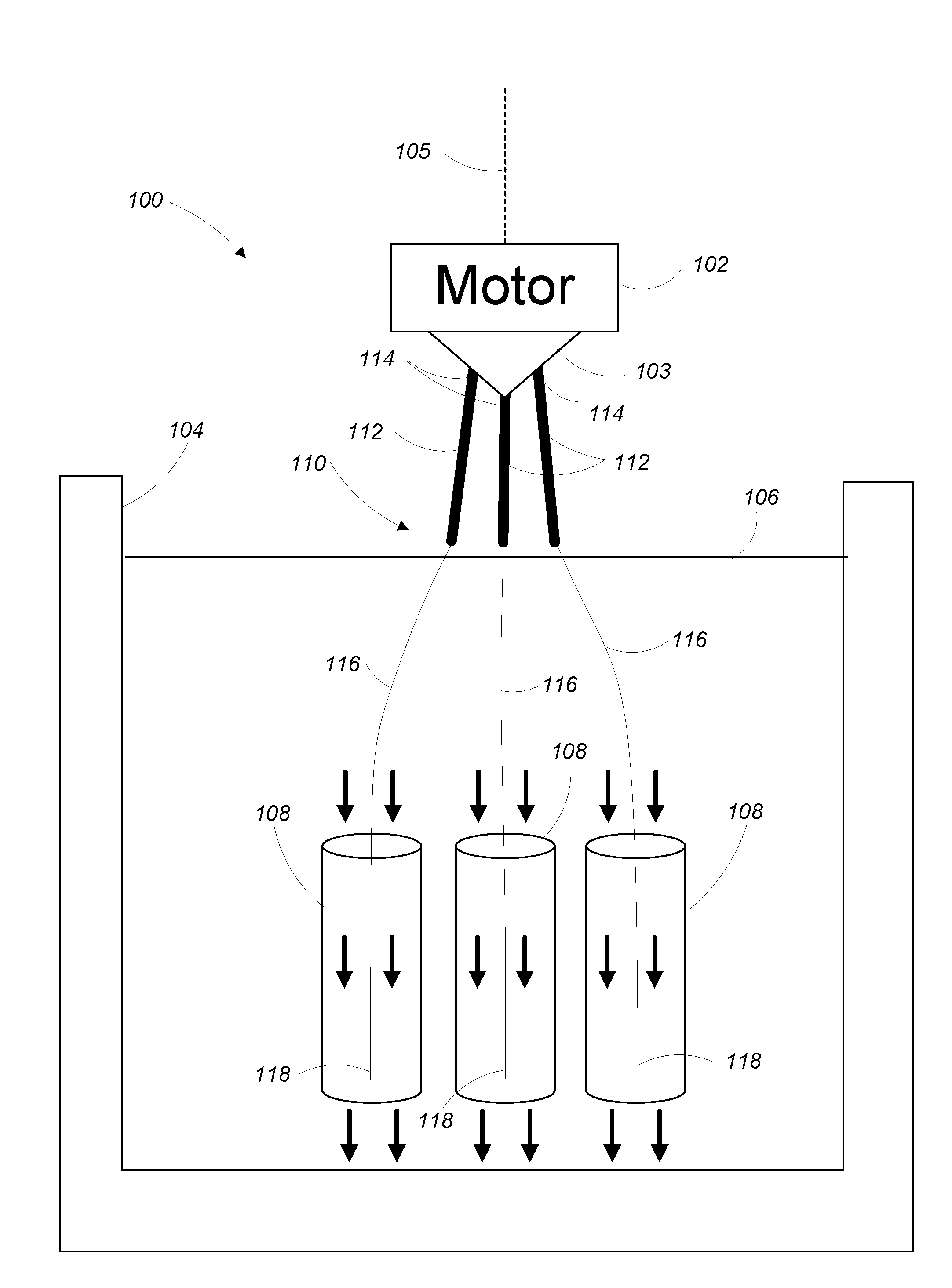
[0025] FIG. 1 is a wire fabrication system.
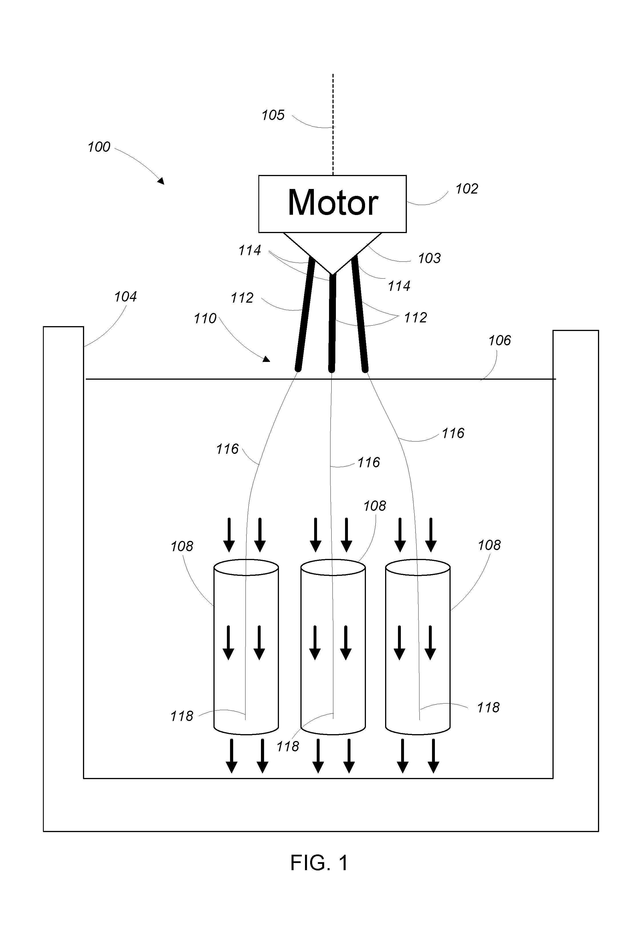
[0026] FIG. 2 shows the wire fabrication system of FIG. 1 with a partially fabricated wire.
[0027] FIG. 3 shows a wire prepared for attachment to the wire fabrication system of FIG. 1.
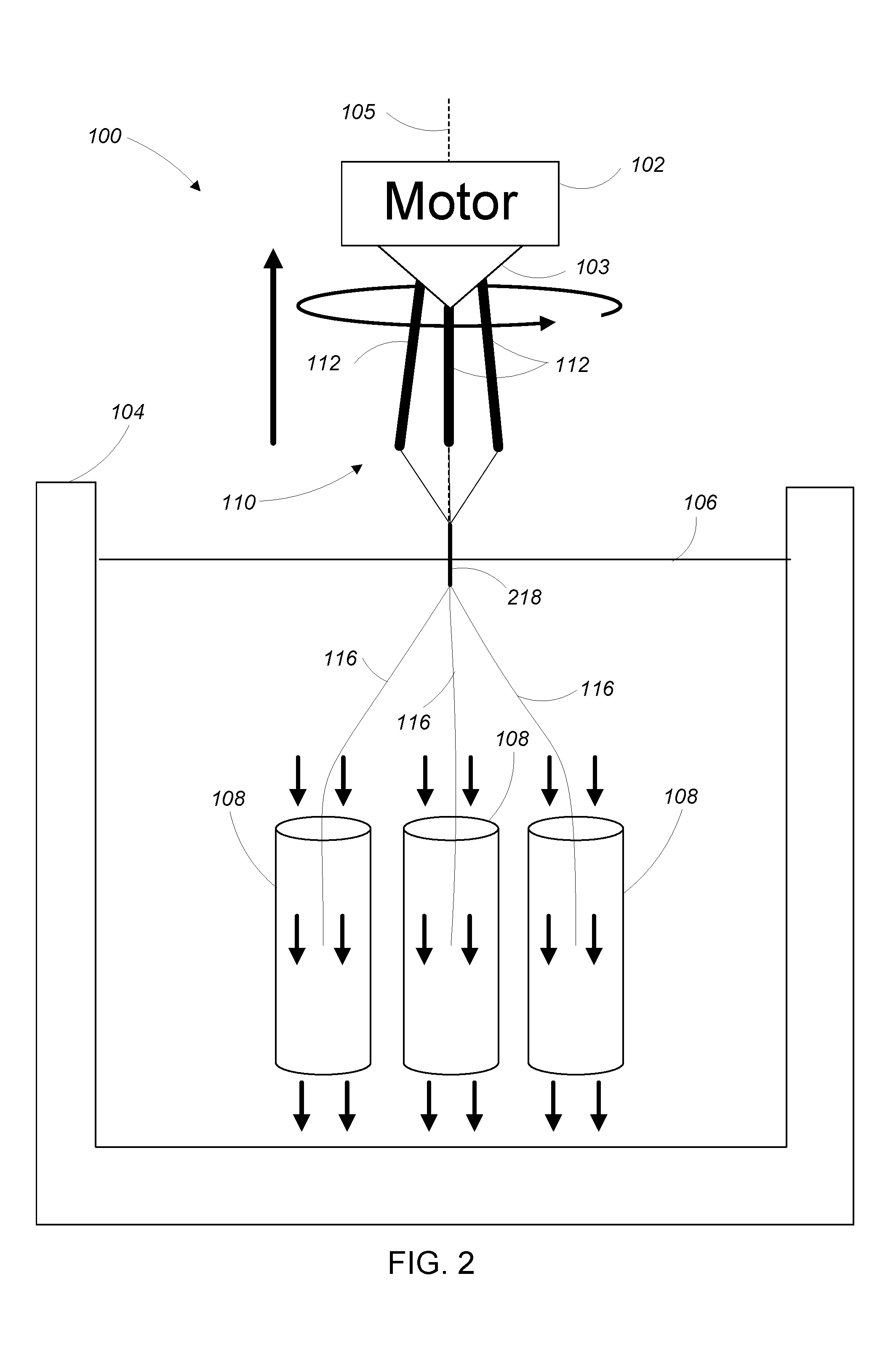
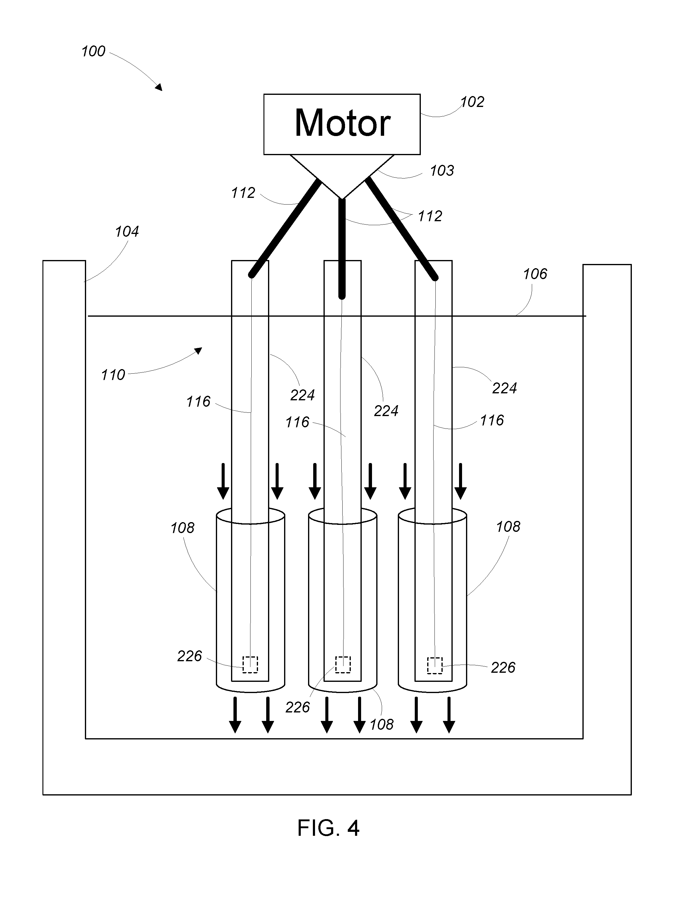
[0028] FIG. 4 shows the prepared wires of FIG. 3 attached to the wire fabrication system of FIG. 1.
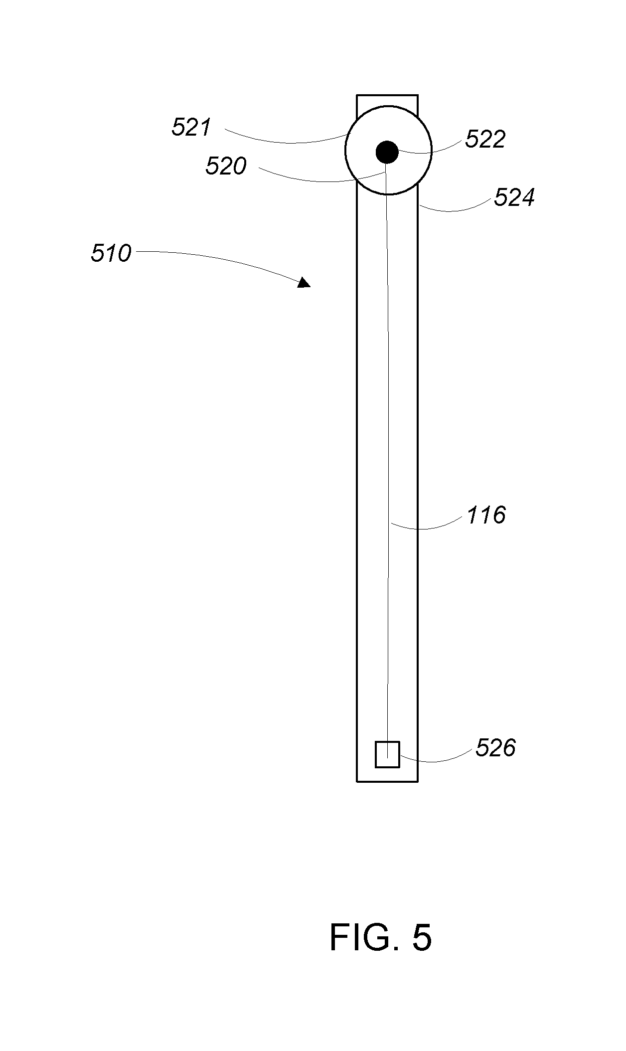
[0029] FIG. 5 shows another wire prepared for attachment to a wire fabrication system.
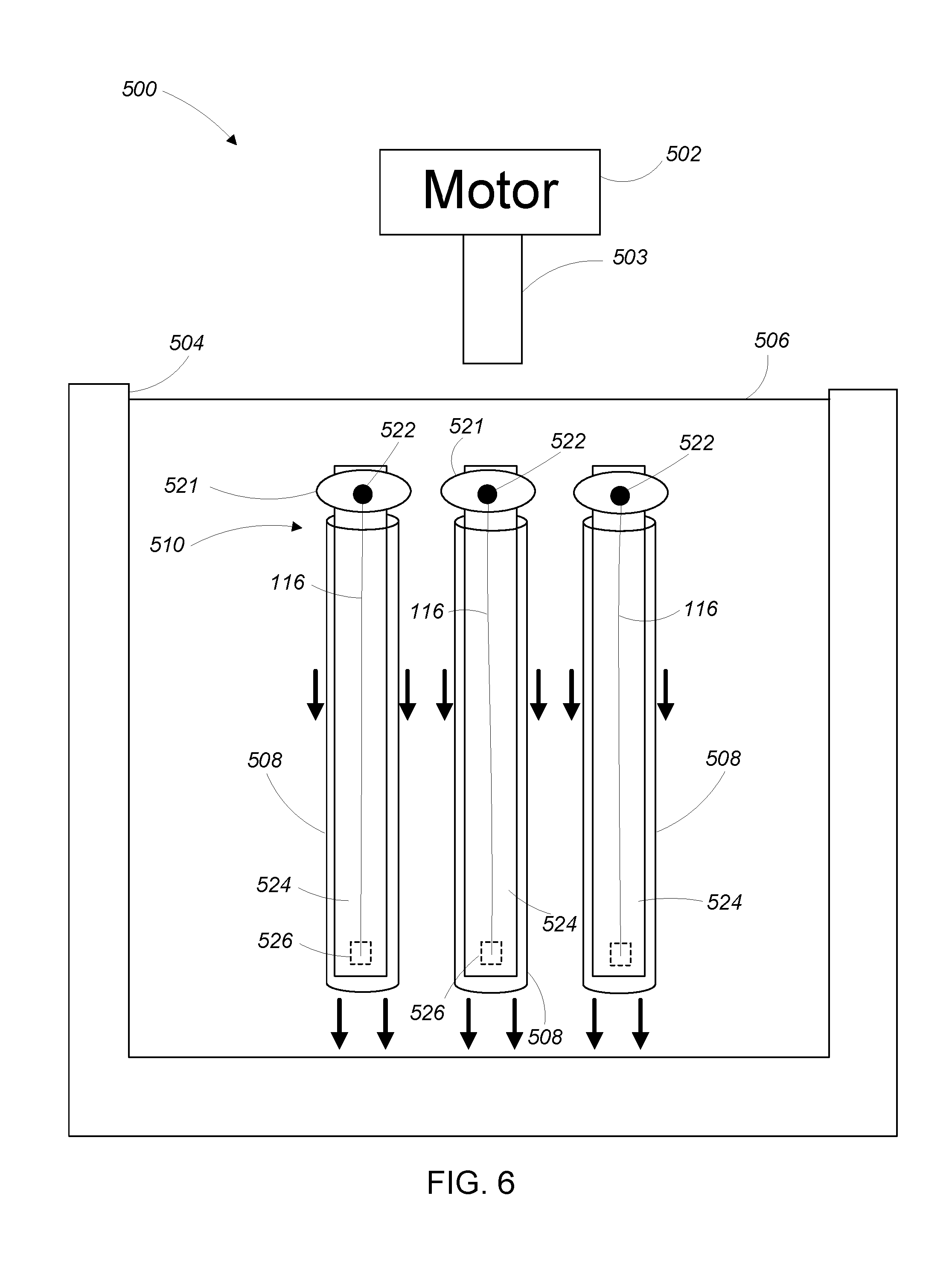
[0030] FIG. 6 shows the prepared wires of FIG. 5 inserted into the fluid channels of another wire fabrication system.
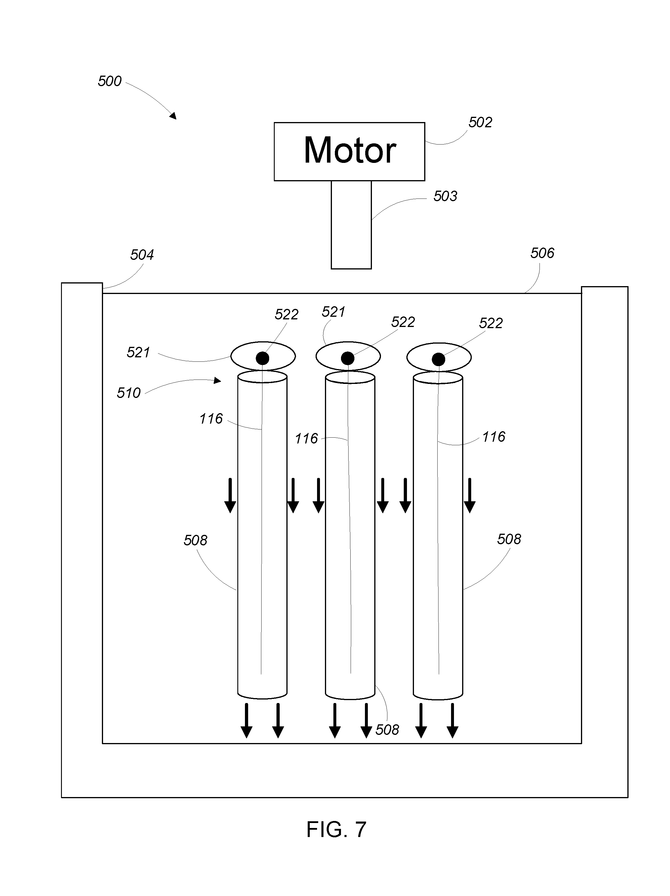
[0031] FIG. 7 shows the prepared wires of FIG. 6 with the substrate removed from the fluid channels of the wire fabrication system.
[0032] FIG. 8 shows the prepared wires of FIG. 7 attached to the wire fabrication system.
DESCRIPTION
[0033] Referring to FIGS. 1 and 2, a wire fabrication system 100 is configured to manipulate individual wires and fibers (sometimes collectively referred to as "wires") to form bundles of multiple wires or fibers.
[0034] The wire fabrication system 100 includes a motor 102 (e.g., a rotary electric motor) positioned above a fluid chamber 104. The motor 102 includes a rotatable spindle 103 (sometimes referred to as an attachment member or attachment point) and is movable along an axis 105 such that a distance between the motor 102 and the fluid chamber 104 can be increased or decreased.
[0035] The fluid chamber 104 is filled with a fluid 106 (e.g., water or oil) and includes a number of fluid channels 108. The fluid 106 in the fluid channels 108 flows in a direction away from the motor 102, as is indicated by the arrows directed away from the motor 102 in FIGS. 1 and 2. In some examples, the flow of fluid through the fluid channels 108 is caused by one or more pumps or propellers (not shown).
[0036] A number of wire assemblies 110 extend from the spindle 103 of the motor 102 and into the fluid channels 108 in the fluid chamber 104. Each wire assembly 110 includes an attachment wire 112 at a first end 114 of the wire assembly 110 and a wire 116 affixed to the attachment wire 112. The wire 116 extends from the attachment wire 112 to a second end 118 of the wire assembly 110.
[0037] When the wire assemblies 110 are placed in the wire fabrication system 100, the attachment wire 112 at the first end 114 of each wire assembly 110 is affixed to the spindle 103 of the motor 102 and at least a portion of the wire 116 the wire assembly 110 is disposed in one of the fluid channels 108 (as is shown in FIGS. 1 and 2).
[0038] The fluid moving through the fluid channels 108 subjects the wires 116 in the fluid channels 108 to an axial drag force that pulls the wires 116 in a direction away from the motor 102. Very generally, the axial drag force is hydrodynamically controlled to maintain tension on the wires 116 without breaking the wires 116.
[0039] In general, the hydrodynamic control of the axial drag force on a given wire 116 is accomplished by varying either the relative velocity between the fluid in the fluid channel 108 and the wire 116, the viscosity of the fluid in the fluid channel 108, or both. The relative velocity between the fluid in the fluid channel 108 and the wire 116 is adjustable by varying the fluid flow rate within the channel or by varying the wire velocity within the channel, or both. The viscosity of the fluid in the fluid channel 108 is adjustable by, for example, varying the type of fluid used, varying a ratio of fluids with different viscosities used in a mixture of fluids, varying a temperature of the fluid, applying an electric field to the fluid, or applying a magnetic field to the fluid.
[0040] Referring to FIG. 2, in operation, the motor 102 rotates the spindle 103 about the axis 105 while the motor 102 is moved along the axis 105 in a direction away from the fluid chamber 104. As the motor 102 moves away from the fluid chamber 104, the wires 116 are pulled through the fluid channels 108 while still under tension, and the rotation of the spindle 103 twists the taut wires 116 to form a twisted (or bundled) section of wire 218. A pitch of the twist in the twisted wire is determined by the ratio of the linear velocity of the motor in the direction away from the fluid chamber 104 and the rotational velocity of the motor 102 (provided that the tension applied to the wires is sufficient to provide the necessary bending force for a desired bend radius).
[0041] The force required for twisting the wires 116 is estimated by modeling the wires using the electrostatics of bending a slender rod. For an approximately 1 .mu.m diameter copper wire, twisting with a pitch of approximately 50 .mu.m requires .mu.N or smaller forces, depending on the point of application of the force. The force on the wires from axial fluid drag can be estimated as Stokes drag using the equation
F.apprxeq.4.pi..mu.lu/ln(l/a)
where .mu. is the dynamic viscosity of the fluid, u is the velocity of the fluid relative to the wire, l is the wire length over which the drag force is operating, and a is the wire radius.
[0042] For example, if the fluid 106 in the fluid chamber 104 is water, the wires can be twisted to a pitch of approximately 50 .mu.m using a fluid velocity of approximately 1 m/min, which is estimated to generate less than 50 nN of force per millimeter of wire. If necessary, larger drag forces can be generated by increasing the flow rate of the fluid, decreasing a cross-sectional area of the fluid channels 108, or using a fluid with a higher viscosity.
[0043] Referring to FIG. 3, in some examples the wire assemblies 110 are prepared prior to being placed in the wire fabrication system. To prepare a wire assembly, a wire 116 is provided with a predetermined length. The wire 116 is then affixed to a carrier substrate 224 (e.g., a 25 mm.times.5 mm.times.1 mm glass substrate) using a soluble adhesive 226 (e.g., a water-soluble adhesive if the fluid 106 includes water). An attachment wire 112 having a greater diameter (e.g., a 100 .mu.m diameter) than the wire 116 is then affixed to first end 220 of the wire 116 using a permanent adhesive 222.
[0044] Referring to FIG. 4, to place the prepared wire assemblies 110 into the wire fabrication system 100, the substrates 224 with the wires 116 affixed thereto are placed into the fluid channels 108. The attachment wires 112 are attached to the spindle 103 of the motor 102. In the presence of the fluid 106 in the fluid channels 108, the soluble adhesive 226 dissolves and the wires 116 are no longer affixed to the substrate 224 (i.e., the wires 116 are freely floating in the fluid channels 108).
[0045] In some examples, the substrates 224 are removed from the fluid channels 108 once the soluble adhesive 226 is dissolved (see FIG. 1). In other examples, the substrates 224 remain in the fluid channels 108 during operation of the wire fabrication system 100.
[0046] Referring to FIGS. 5-7, in another example, rather than attaching an attachment wire to the wire 116, a small (e.g., 2-10 mm diameter.times.about 100 .mu.m thick) mu-metal (or other ferromagnetic metal) disk 521 is attached to the end of the wire 116. In operation, the mu-metal disks are attached to the spindle 103 of the motor 102 by magnetic force.
[0047] Referring now to FIG. 5, in some examples the wire assemblies 510 are prepared prior to being placed in a wire fabrication system 500. To prepare a wire assembly 510, a mu-metal disk 521 is affixed to a carrier substrate 524 using a soluble adhesive (not shown). A wire 116 is provided with a predetermined length. The wire 116 is affixed to the carrier substrate 524 (e.g., a 25 mm.times.5 mm.times.1 mm glass substrate) using a soluble adhesive 526 (e.g., a water-soluble adhesive if the fluid 506 includes water). A first end 520 of wire 116 is affixed to the mu-metal disk 521 using a permanent adhesive 522.
[0048] Referring to FIGS. 6 and 7, to place the prepared wire assemblies 510 into the wire fabrication system 500, the substrates 524 with the wires 116 affixed thereto are placed into the fluid channels 508. In the presence of the fluid 506 in the fluid channels 508, the soluble adhesive 526 attaching the wires 116 and the mu-metal disks 521 to the carrier substrates 524 dissolves such that both the mu-metal disks 521 and the wires 116 are no longer affixed to the substrate 524 (i.e., the mu-metal disks 521 and the wires 116 are freely floating in the fluid channels 508). The mu-metal disks 521 are dimensioned such that they are too large to move into or through the fluid channels 508.
[0049] Referring to FIG. 8, with the wire assemblies 510 in the fluid channels, the motor 502 is positioned in proximity to the mu-metal disks 521 and the spindle 503 of the motor is magnetized (e.g., by inserting a magnet into the spindle or turning on an electromagnet). The magnetized spindle 503 attracts the mu-metal disks 521, attaching the mu-metal disks to the spindle 503. The wire fabrication system 500 then proceeds to draw the wires 116 through the fluid channels 508 while rotating the spindle 503 (as was described in the examples above) to form the twisted wire.
[0050] In some examples, upon completion of wire fabrication, the spindle 503 is demagnetized (e.g., by removing the magnet or turning off the electromagnet) such that the mu-metal disks 521 can be easily removed from the spindle 503. In some examples, the polarity of the electromagnet is reversed to force the mu-metal disks 521 away from the spindle 503, making removal of the mu-metal disks 503 even easier.
[0051] It is to be understood that the foregoing description is intended to illustrate and not to limit the scope of the invention, which is defined by the scope of the appended claims. Other embodiments are within the scope of the following claims.
* * * * *
D00000
D00001
D00002
D00003
D00004
D00005
D00006
D00007
D00008
XML
uspto.report is an independent third-party trademark research tool that is not affiliated, endorsed, or sponsored by the United States Patent and Trademark Office (USPTO) or any other governmental organization. The information provided by uspto.report is based on publicly available data at the time of writing and is intended for informational purposes only.
While we strive to provide accurate and up-to-date information, we do not guarantee the accuracy, completeness, reliability, or suitability of the information displayed on this site. The use of this site is at your own risk. Any reliance you place on such information is therefore strictly at your own risk.
All official trademark data, including owner information, should be verified by visiting the official USPTO website at www.uspto.gov. This site is not intended to replace professional legal advice and should not be used as a substitute for consulting with a legal professional who is knowledgeable about trademark law.