Cleaning Device, Plating Device Including The Same, And Cleaning Method
OHASHI; Hirotaka ; et al.
U.S. patent application number 16/359365 was filed with the patent office on 2019-10-03 for cleaning device, plating device including the same, and cleaning method. This patent application is currently assigned to EBARA CORPORATION. The applicant listed for this patent is EBARA CORPORATION. Invention is credited to Takahiro ABE, Hirotaka OHASHI.
| Application Number | 20190301044 16/359365 |
| Document ID | / |
| Family ID | 68056857 |
| Filed Date | 2019-10-03 |


View All Diagrams
| United States Patent Application | 20190301044 |
| Kind Code | A1 |
| OHASHI; Hirotaka ; et al. | October 3, 2019 |
CLEANING DEVICE, PLATING DEVICE INCLUDING THE SAME, AND CLEANING METHOD
Abstract
There is provided a cleaning device capable of conveying a substrate even when having large warpage. A cleaning device configured to clean a substrate W1 includes a horizontal conveyance mechanism 56 configured to convey the substrate W1 to be subjected to cleaning processing. Furthermore, the cleaning device includes a pressurizing roller 70 provided at a position facing the horizontal conveyance mechanism 56 with the substrate W1 therebetween and configured to press the substrate W1 against the horizontal conveyance mechanism 56, and a roller moving mechanism 72 configured to move the pressurizing roller 70 toward the horizontal conveyance mechanism 56 to cause the pressurizing roller 70 to press the substrate W1 against the horizontal conveyance mechanism 56.
| Inventors: | OHASHI; Hirotaka; (Tokyo, JP) ; ABE; Takahiro; (Tokyo, JP) | ||||||||||
| Applicant: |
|
||||||||||
|---|---|---|---|---|---|---|---|---|---|---|---|
| Assignee: | EBARA CORPORATION Tokyo JP |
||||||||||
| Family ID: | 68056857 | ||||||||||
| Appl. No.: | 16/359365 | ||||||||||
| Filed: | March 20, 2019 |
| Current U.S. Class: | 1/1 |
| Current CPC Class: | C25D 17/00 20130101; C25D 21/12 20130101; C25D 21/08 20130101; C25D 5/48 20130101 |
| International Class: | C25D 5/48 20060101 C25D005/48 |
Foreign Application Data
| Date | Code | Application Number |
|---|---|---|
| Mar 27, 2018 | JP | 2018-060348 |
| Mar 27, 2018 | JP | 2018-060350 |
Claims
1. A cleaning device configured to clean a target object, comprising: a conveyance mechanism configured to convey the target object to be subjected to cleaning processing; a pressurizing roller provided at a position facing the conveyance mechanism with the target object therebetween, the pressurizing roller being configured to press the target object against the conveyance mechanism; and a roller moving mechanism configured to move the pressurizing roller toward the conveyance mechanism to cause the pressurizing roller to press the target object against the conveyance mechanism.
2. The cleaning device according to claim 1, wherein the number of the pressuring rollers is at least four.
3. The cleaning device according to claim 1, further comprising: a drive mechanism configured to rotationally drive the pressurizing roller.
4. A plating device, comprising: the cleaning device according to claim 1.
5. A method for cleaning a target object in a cleaning device configured to clean the target object, the cleaning device comprising a conveyance mechanism configured to convey the target object to be subjected to cleaning processing, a pressurizing roller provided at a position facing the conveyance mechanism with the target object therebetween, the pressurizing roller being configured to press the target object against the conveyance mechanism, and a roller moving mechanism configured to move the pressurizing roller toward the conveyance mechanism to cause the pressurizing roller to press the target object against the conveyance mechanism, the method comprising: a process of mounting the target object on the conveyance mechanism; a process of moving the pressurizing roller toward the conveyance mechanism by the roller moving mechanism to cause the pressurizing roller to press the target object against the conveyance mechanism; and a process of conveying the target object in a state in which the target object is pressed against the conveyance mechanism.
6. A cleaning device configured to clean a target object, comprising: a supporting part configured to support the target object that has been subjected to plating processing and cleaning processing; a pressing part provided at a position facing the supporting part with the target object therebetween, the pressing part being configured to press the target object against the supporting part; a moving mechanism configured to move the pressing part toward the supporting part to cause the pressing part to press the target object against the supporting part; and a film thickness measuring part configured to measure a film thickness of a plated film of the target object.
7. The cleaning device according to claim 6, wherein the supporting part is a conveyance mechanism configured to convey the target object.
8. The cleaning device according to claim 6, wherein the pressing part has a roller, and the roller is configured to press the target object against the supporting part.
9. The cleaning device according to claim 6, wherein the number of the rollers is at least four.
10. The cleaning device according to claim 6, wherein the film thickness measuring part is moved for the measurement to measure a film thickness of a plated film of the target object at a plurality of points of the target object.
11. The cleaning device according to claim 6, wherein a plurality of the film thickness measuring parts are provided.
12. The cleaning device according to claim 6, wherein the film thickness measuring part has an eddy current sensor.
13. The cleaning device according to claim 6, wherein the target object has a resist, and the film thickness measuring part is configured to measure the film thickness of the plated film of the target object having the resist.
14. A plating device, comprising the cleaning device according to claim 6.
15. A method for cleaning a target object in a cleaning device configured to clean the target object, the cleaning device comprising a supporting part configured to support the target object that has been subjected to plating processing and cleaning processing, a pressing part provided at a position facing the supporting part with the target object therebetween, the pressing part being configured to press the target object against the supporting part, a moving mechanism configured to move the pressing part toward the supporting part to cause the pressing part to press the target object against the supporting part, and a film thickness measuring part configured to measure a film thickness of a plated film of the target object, the method comprising: a process of mounting the target object on the supporting part; a process of moving the pressing part toward the supporting part by the moving mechanism to cause the pressing part to press the target object against the supporting part; and a process of measuring the film thickness of the plated film of the target object using the film thickness measuring part in a state in which the target object is pressed against the supporting part.
Description
CROSS REFERENCE TO RELATED APPLICATIONS
[0001] This application claims priority to Japanese Application No. 2018-060348, filed Mar. 27, 2018 and Japanese Application No. 2018-060350, filed Mar. 27, 2018, the entire content of which is hereby incorporated by reference.
TECHNICAL FIELD
[0002] The present invention relates to a cleaning device, a plating device including the same, and a cleaning method.
BACKGROUND ART
[0003] It has been a conventional practice to form wires and bumps (protruded electrodes), for example, on the surface of a substrate such as a semiconductor wafer or a printed board. This formation of wires, bumps, and the like has been performed by a known method called an electrolytic plating.
[0004] A plating device used in the electrolytic plating performs plating processing on a circular substrate such as a wafer typically having a diameter of 300 mm. In addition to such a circular substrate, however, a rectangular substrate has been required to be plated recently. In conventional plating of a circular substrate through a plating device, the plated circular substrate has been cleaned and dried at a spin rinse dryer (SRD). The SRD cleans and dries a substrate while rotating the substrate.
[0005] The size or stiffness of a circular substrate or a rectangular substrate differs between the kinds of product. When having a small stiffness, a rectangular substrate potentially becomes curved. In a cleaning device configured to clean a substrate, when the substrate is conveyed into the cleaning device by conveying rollers, the contact area between the substrate having large warpage and the conveying rollers becomes smaller. For that reason, the conveying rollers rotate idly, and thus potentially unable to convey the substrate.
[0006] Even when the substrate having large warpage can be conveyed, such a substrate interferes with a slit as an inlet to the processing area in the cleaning device, and thus potentially unable to pass through the slit. This is because the width of the slit is designed as narrow as possible to prevent gas and the like in the cleaning device from leaking to the outside of the cleaning device.
[0007] Incidentally, the cleaning device configured to measure the film thickness of a plated film after cleaning the plated film is disclosed in Japanese Patent Laid-Open No. 2005-240108. The size or stiffness of a circular substrate or a rectangular substrate differs between the kinds of product. When having a small stiffness, a rectangular substrate potentially becomes curved. Since the technique disclosed in Japanese Patent Laid-Open No. 2005-240108 does not cover the substrate having warpage, the warpage causes a problem in that the film thickness of the plated film cannot be measured accurately.
[0008] In the technique disclosed in Japanese Patent Laid-Open No. 2005-240108, the resist is removed after plating, and then the film thickness of the plated film is measured. Thus, when the measurement result fails due to small film thickness of the plated film and/or uneven film thickness, it is necessary to apply the resist on a substrate again to perform plating again or to dispose of the substrate. For that reason, there is a problem in that the costs are increased.
CITATION LIST
Patent Literature
[0009] PTL 1: Japanese Patent Laid-Open No. 2018-6404
[0010] PTL 2: Japanese Patent Laid-Open No. 2005-240108
SUMMARY OF INVENTION
Technical Problem
[0011] An embodiment of the present invention is intended to solve the above-described problems, and an object thereof is to provide a cleaning device capable of conveying a substrate even when having large warpage.
[0012] An object of another embodiment of the present invention is to provide a cleaning device capable of measuring a film thickness of a plated film even when a substrate has large warpage.
[0013] An object of another embodiment of the present invention is to provide a cleaning device capable of measuring a film thickness of a plated film without removing the resist.
Solution to Problem
[0014] In order to solve the above-described problems, a first aspect provides a cleaning device configured to clean a target object, the cleaning device comprising a conveyance mechanism configured to convey the target object to be subjected to cleaning processing, a pressurizing roller provided at a position facing the conveyance mechanism with the target object therebetween, the pressurizing roller being configured to press the target object against the conveyance mechanism, and a roller moving mechanism configured to move the pressurizing roller toward the conveyance mechanism to cause the pressurizing roller to press the target object against the conveyance mechanism.
[0015] In the present embodiment, the pressurizing rollers provided at a position facing the conveyance mechanism with the target object therebetween and configured to press the target object against the conveyance mechanism is moved toward the conveyance mechanism by the roller moving mechanism so that the pressurizing rollers press the target object against the conveyance mechanism. Accordingly, even when a substrate (target object) has large warpage, the substrate is pressed against conveying rollers (conveyance mechanism) to prevent the conveying rollers from rotating idly. The substrate pressed by the pressurizing rollers can be conveyed to a processing area by the conveying rollers.
[0016] The pressurizing rollers press the substrate against the conveying rollers, to thereby prevent the substrate whose warpage has been corrected from interfering with a slit as an inlet of the processing area.
[0017] A second aspect provides the cleaning device according to the first aspect in which the number of the pressuring rollers is at least four.
[0018] A third aspect provides the cleaning device according to the first aspect or the second aspect comprising a drive mechanism configured to rotationally drive the pressurizing roller.
[0019] A fourth aspect provides a plating device comprising the cleaning device according to any one of the first aspect to the third aspect.
[0020] A fifth aspect provides a method for cleaning a target object in a cleaning device configured to clean the target object, the cleaning device comprising a conveyance mechanism configured to convey the target object to be subjected to cleaning processing, a pressurizing roller provided at a position facing the conveyance mechanism with the target object therebetween, the pressurizing roller being configured to press the target object against the conveyance mechanism, and a roller moving mechanism configured to move the pressurizing roller toward the conveyance mechanism to cause the pressurizing roller to press the target object against the conveyance mechanism, the method comprising a process of mounting the target object on the conveyance mechanism, a process of moving the pressurizing roller toward the conveyance mechanism by the roller moving mechanism to cause the pressurizing roller to press the target object against the conveyance mechanism, and a process of conveying the target object in a state in which the target object is pressed against the conveyance mechanism.
[0021] In order to solve the above-described problems, a sixth aspect provides a cleaning device configured to clean a target object, the cleaning device comprising a supporting part configured to support the target object that has been subjected to plating processing and cleaning processing, a pressing part provided at a position facing the supporting part with the target object therebetween, the pressing part being configured to press the target object against the supporting part, a moving mechanism configured to move the pressing part toward the supporting part to cause the pressing part to press the target object against the supporting part, and a film thickness measuring part configured to measure a film thickness of a plated film of the target object.
[0022] In the present embodiment, the pressing part can press the target object against the support part, whereby the film thickness can be measured in a state in which the warpage of the substrate has been corrected. Accordingly, the film thickness of the plated film can be measured accurately. According to the present embodiment, there is provided a cleaning device capable of measuring a film thickness of a plated film even when a substrate has large warpage.
[0023] A seventh aspect provides the cleaning device according to the sixth aspect, in which the supporting part is a conveyance mechanism configured to convey the target object.
[0024] An eighth aspect provides the cleaning device according to the sixth aspect or the seventh aspect in which the pressing part has a roller, and the roller is configured to press the target object against the supporting part.
[0025] A ninth aspect provides the cleaning device according to any one of the sixth aspect to the eighth aspect in which the number of the rollers is at least four.
[0026] A tenth aspect provides the cleaning device according to any one of the sixth aspect to the ninth aspect in which the film thickness measuring part is moved for the measurement to measure a film thickness of a plated film of the target object at a plurality of points of the target object.
[0027] An eleventh aspect provides the cleaning device according to any one of the sixth aspect to the tenth aspect in which a plurality of the film thickness measuring parts are provided.
[0028] A twelfth aspect provides the cleaning device according to any one of the sixth aspect to the eleventh aspect in which the film thickness measuring part has an eddy current sensor.
[0029] A thirteenth aspect provides the cleaning device according to any one of the sixth aspect to the twelfth aspect in which the target object has a resist, and the film thickness measuring part is configured to measure the film thickness of the plated film of the substrate having the resist. In the present embodiment, the film thickness of the plated film of the substrate having the resist is measured, thereby eliminating the need for the removal of the resist. According to the present embodiment, there is provided a cleaning device capable of measuring a film thickness of a plated film, without removing the resist.
[0030] When the measurement result fails due to small film thickness of the plated film and/or uneven film thickness, the substrate can be plated again without being applied with the resist again. The substrate can be plated again without disposing of the rejected substrate. Therefore, the costs can be reduced.
[0031] A fourteenth aspect provides a plating device comprising the cleaning device according to any one of the sixth aspect to the thirteenth aspect.
[0032] A fifteenth aspect provides a method for cleaning a target object in a cleaning device configured to clean the target object, the cleaning device comprising a supporting part configured to support the target object that has been subjected to plating processing and cleaning processing, a pressing part provided at a position facing the supporting part with the target object therebetween, the pressing part being configured to press the target object against the supporting part, a moving mechanism configured to move the pressing part toward the supporting part to cause the pressing part to press the target object against the supporting part, and a film thickness measuring part configured to measure a film thickness of a plated film of the target object, the method comprising a process of mounting the target object on the supporting part, a process of moving the pressing part toward the supporting part by the moving mechanism to cause the pressing part to press the target object against the supporting part, and a process of measuring the film thickness of the plated film of the target object using the film thickness measuring part in a state in which the target object is pressed against the supporting part.
BRIEF DESCRIPTION OF DRAWINGS
[0033] FIG. 1 is an entire layout diagram of a plating device including a cleaning device according to the present embodiment;
[0034] FIG. 2 is a schematic sectional side view of the cleaning device; and
[0035] FIG. 3 is a diagram illustrating a problem arising when pressurizing rollers are not provided;
[0036] FIG. 4 is a diagram illustrating a problem arising when the pressurizing rollers are not provided;
[0037] FIG. 5 is a front view illustrating the pressurizing rollers and a roller moving mechanism according to the present embodiment;
[0038] FIG. 6 is a front view illustrating the pressurizing rollers and the roller moving mechanism according to the present embodiment;
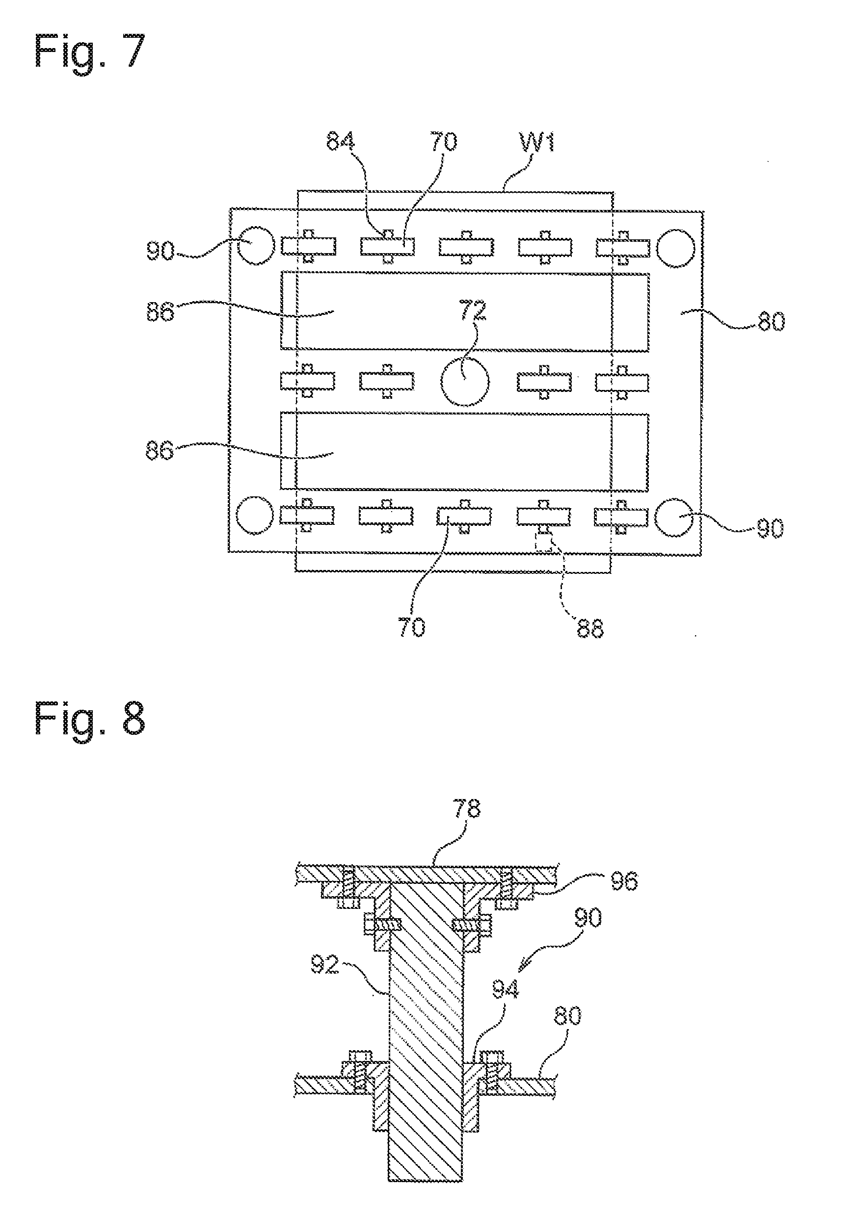
[0039] FIG. 7 is a plan view illustrating the pressurizing rollers and the roller moving mechanism according to the present embodiment;
[0040] FIG. 8 is a schematic sectional side view of a guide part;
[0041] FIG. 9 is a schematic sectional side view of a cleaning device according to another embodiment;
[0042] FIG. 10 is a diagram illustrating a problem arising when pressurizing rollers are not provided;
[0043] FIG. 11 is a front view illustrating a pressing part, a moving mechanism, and a film thickness measuring part according to another embodiment;
[0044] FIG. 12 is a front view illustrating the pressing part, the moving mechanism, and the film thickness measuring part according to another embodiment; and
[0045] FIG. 13 is a schematic sectional side view of a guide part.
DESCRIPTION OF EMBODIMENTS
[0046] The following describes embodiments of the present invention with reference to the accompanying drawings. Note that in each embodiment to be described below, any identical or equivalent members are denoted by an identical reference sign, and duplicate description thereof will be omitted. Features shown in each embodiment are also applicable to the other embodiments unless they are inconsistent with each other. FIG. 1 is an entire layout diagram of a plating device including a cleaning device according to the present embodiment. As illustrated in FIG. 1, this plating device 100 mainly includes a loading/unloading unit 110 configured to load a substrate (corresponding to an exemplary target object) onto a substrate holder and unload the substrate from the substrate holder, a processing unit 120 configured to process the substrate, and a cleaning part 50a. The processing unit 120 includes a preprocessing-postprocessing unit 120A configured to perform preprocessing and postprocessing on the substrate, and a plating processing unit 120B configured to perform plating processing on the substrate. Substrates processed through the plating device 100 include rectangular and circular substrates. The rectangular substrates include rectangular printed boards and any other rectangular plating objects.
[0047] The loading/unloading unit 110 includes two cassette tables 25 and a substrate attaching mechanism 29. A cassette 25a housing a substrate such as a semiconductor wafer or a printed board is mounted on each cassette table 25. The substrate attaching mechanism 29 is configured to attach and detach the substrate to and from a substrate holder (not illustrated). A stocker 30 for housing the substrate holder is provided near (for example, below) the substrate attaching mechanism 29. A substrate conveying device 27 including a conveyance robot configured to convey the substrate between these components 25, 29, and 30 is disposed in the center of the components. The substrate conveying device 27 is configured to be movable by a movement mechanism 28.
[0048] The cleaning part 50a includes a cleaning device 50 configured to clean and dry a substrate that has been subjected to plating processing. The substrate conveying device 27 is configured to convey the substrate that has been subjected to plating processing into the cleaning device 50 and take the cleaned substrate out of the cleaning device 50. The cleaning device 50 will be described in detail with reference to FIG. 2 later.
[0049] The preprocessing-postprocessing unit 120A includes a pre-wet bath 32, a pre-soak bath 33, a pre-rinse bath 34, a blow bath 35, and a rinse bath 36. In the pre-wet bath 32, a substrate is immersed into pure water. In the pre-soak bath 33, an oxide film on the surface of a conductive layer such as a seed layer formed on the surface of the substrate is removed by etching. In the pre-rinse bath 34, the pre-soaked substrate is cleaned by cleaning liquid (for example, pure water) together with a substrate holder. In the blow bath 35, liquid on the cleaned substrate is removed. In the rinse bath 36, the substrate that has been subjected to plating is cleaned by cleaning liquid together with the substrate holder. The pre-wet bath 32, the pre-soak bath 33, the pre-rinse bath 34, the blow bath 35, and the rinse bath 36 are disposed in this order.
[0050] The plating processing unit 120B includes a plurality of plating baths 39 provided with an overflow bath 38. Each plating bath 39 houses one substrate and performs plating such as copper plating on the surface of the substrate being immersed in plating solution stored inside. The plating solution is not limited to a particular kind, but various kinds of plating solution may be applicable depending on usage.
[0051] The plating device 100 includes a substrate-holder conveying device 37 disposed beside these instruments and employing, for example, a linear motor scheme to convey the substrate holder together with the substrate between these instruments. The substrate-holder conveying device 37 is configured to convey the substrate holder between the substrate attaching mechanism 29, the pre-wet bath 32, the pre-soak bath 33, the pre-rinse bath 34, the blow bath 35, the rinse bath 36, and the plating baths 39.
[0052] The following describes the cleaning device 50 illustrated in FIG. 1 in detail. FIG. 2 is a schematic sectional side view of the cleaning device 50. The cleaning device 50 includes an inlet 51 for a substrate W1, a first conveyance path 52, a vertical conveyance path 53, a second conveyance path 54, and an outlet 55 for the substrate W1. As illustrated in FIG. 2, the first conveyance path 52 and the second conveyance path 54 are vertically arranged side by side, and the first conveyance path 52 is positioned below the second conveyance path 54. The first conveyance path 52 is a path that is communicated with the inlet 51 and on which the substrate W1 input through the inlet 51 is conveyed. The second conveyance path 54 is a path on which the substrate W1 is conveyed in a direction opposite to a direction in which the substrate W1 is conveyed on the first conveyance path 52. The second conveyance path 54 is connected with the first conveyance path 52 through the vertical conveyance path 53 and communicated with the outlet 55. The vertical conveyance path 53 is a path extending in the vertical direction to connect the first conveyance path 52 and the second conveyance path 54.
[0053] The inlet 51 is provided with an inlet shutter 51a for opening and closing the inlet 51. The outlet 55 is provided with an outlet shutter 55a for opening and closing the outlet 55. When the cleaning device 50 is mounted on the plating device 100 as in the present embodiment, or is mounted on, for example, a CMP device, particles generated by cleaning float in the cleaning device 50, and thus atmosphere in the cleaning device 50 has been degraded in terms of cleanness as compared to that in the plating device 100 or, for example, the CMP device. When negative pressure is maintained inside the cleaning device 50, reduction can be achieved in flow of particles from the inside of the cleaning device 50 to the outside thereof. However, negative pressure cannot be maintained inside the cleaning device 50, for example, when a pressure adjusting device is failed. In the present embodiment, since the inside and outside of the cleaning device 50 can be separated by the inlet shutter 51a and the outlet shutter 55a, further reduction can be achieved in the external flow of particles from the inside of the cleaning device 50.
[0054] As illustrated in FIG. 2, the first conveyance path 52 is provided with a horizontal conveyance mechanism 56 (conveyance mechanism) including, for example, a plurality of rollers that convey the substrate W1 to the vertical conveyance path 53. The rollers of the horizontal conveyance mechanism 56 may be disposed to only contact a predetermined place of the substrate W1 depending on, for example, the strength and material of the substrate W1. For example, the rollers of the horizontal conveyance mechanism 56 may be disposed to only contact a central part and both edge parts of the substrate W1 in the width direction. An alignment mechanism configured to adjust the position of the substrate W1 input through the inlet 51 may be provided near the inlet 51 of the first conveyance path 52. With this configuration, the substrate W1 input through the inlet 51 can be placed at an appropriate position on the horizontal conveyance mechanism 56.
[0055] When the substrate W1 is placed at an appropriate position on the horizontal conveyance mechanism 56, pressurizing rollers 7 capable of pressing the substrate W1 against the horizontal conveyance mechanism 56 are configured to move downward in the vertical direction toward the horizontal conveyance mechanism 56 to press the substrate W1 against the horizontal conveyance mechanism 56. A roller moving mechanism 72 is configured to move the pressurizing rollers 70 downward in the vertical direction. The pressurizing rollers 70 and the roller moving mechanism 72 will be described in detail later. The substrate W1 is conveyed toward the inside of a processing area 82 by the horizontal conveyance mechanism 56 in a state in which the substrate W1 is pressed against the horizontal conveyance mechanism 56 by the pressurizing rollers 70.
[0056] The first conveyance path 52 is provided with a cleaning unit 57 configured to clean the substrate W1 and a drying unit 58 configured to dry the substrate W1. In an embodiment, the cleaning unit 57 includes a first cleaning unit 57a and a second cleaning unit 57b positioned downstream of the first cleaning unit 57a. The first cleaning unit 57a cleans the substrate W1 by spraying de-ionized water (DIW; corresponding to exemplary cleaning liquid) onto both or one of the surfaces of the substrate W1. The second cleaning unit 57b removes particles on the surface of the substrate W1 by jet-spraying DIW and gas simultaneously onto both or one of the surfaces of the substrate W1. The gas sprayed by the second cleaning unit 57b may be clean dry air or nitrogen. The first cleaning unit 57a and the second cleaning unit 57b are each what is called a non-contacting cleaning unit configured to clean the substrate W1 with liquid or gas. The drying unit 58 is, for example, what is called an air knife configured to spray compressed gas in a thin layer shape out of an elongated slit to remove or dry cleaning liquid adhering to both or one of the surfaces of the substrate W1. The drying unit 58 is what is called a non-contacting drying unit configured to dry the substrate W1 with gas.
[0057] The first cleaning unit 57a, the second cleaning unit 57b, and the drying unit 58 are each enclosed by an independent chamber. Atmosphere in any opening communicating the chambers is separated by, for example, an air curtain (not illustrated). The first cleaning unit 57a and the second cleaning unit 57b are connected with a DIW supply line 59 for supplying DIW to these units. The second cleaning unit 57b and the drying unit 58 are connected with a gas supply line 60 for supplying gas to these units. The DIW supply line 59 is provided with a filter 59a for capturing particles in DIW and a flow meter 59b configured to measure the flow rate of DIW. The gas supply line 60 is provided with a filter 60a for capturing particles in gas.
[0058] The vertical conveyance path 53 is provided with a vertical conveyance mechanism 61 configured to receive the substrate W1 conveyed by the horizontal conveyance mechanism 56 and convey the substrate W1 in the vertical direction from the first conveyance path 52 to the second conveyance path 54. The vertical conveyance mechanism 61 includes, for example, a supporting table that supports the substrate W1, and an elevation mechanism configured to elevate up and down the supporting table. The vertical conveyance mechanism 61 may include a substrate conveying mechanism such as a roller for passing the substrate W1 from the supporting table to a horizontal conveyance mechanism (not illustrated) provided to the second conveyance path 54. When the first conveyance path 52 and the second conveyance path 54 are vertically arranged side by side as in the present embodiment, the substrate W1 can be conveyed from the first conveyance path 52 to the second conveyance path 54 by the vertical conveyance mechanism 61.
[0059] The second conveyance path 54 is provided with a horizontal conveyance mechanism (not illustrated) for horizontally conveying, to the outlet 55, the substrate W1 conveyed by the vertical conveyance mechanism 61. This horizontal conveyance mechanism may be, for example, a roller similarly to the horizontal conveyance mechanism 56, or a well-known robot hand. The second conveyance path 54 is provided with an air-sending unit 62 such as a fun filter unit (FFU) configured to send gas downward from above. In the example illustrated in FIG. 2, the air-sending unit 62 is provided near each of start and end points of the second conveyance path 54. Examples of the gas sent by the air-sending unit 62 include clean dry air and nitrogen. An alignment mechanism configured to adjust the position of the substrate W1 taken out of the outlet 55 may be provided near the outlet 55 of the second conveyance path 54. With this configuration, the substrate W1 can be placed at an appropriate position on the horizontal conveyance mechanism to allow the substrate conveying device 27 illustrated in FIG. 1 to take the substrate W1 out of the outlet 55 by more reliably holding the substrate W1.
[0060] The following describes a process of cleaning the substrate W1 by using the cleaning device 50 described above. First, the substrate conveying device 27 holds the substrate W1 plated in the plating device 100 illustrated in FIG. 1. By this time, the liquid removal has been performed on the substrate W1 at the blow bath 35 illustrated in FIG. 1, but the surface of the substrate W1 may be wet or dried. When the inlet shutter 51a of the cleaning device 50 is opened, the substrate conveying device 27 inputs the substrate W1 into the cleaning device 50 through the inlet 51. When the substrate W1 is input to the cleaning device 50, the inlet shutter 51a is closed.
[0061] The pressurizing rollers 70 are configured to move downward in the vertical direction toward the horizontal conveyance mechanism 56 to press the substrate W1 against the horizontal conveyance mechanism 56. In the inlet 51, the substrate W1 is conveyed by the horizontal conveyance mechanism 56 in a state of being pressed by the pressurizing rollers 70. The horizontal conveyance mechanism 56 of the cleaning device 50 conveys the substrate W1 input through the inlet 51 along the first conveyance path 52. While being conveyed through the first conveyance path 52, the substrate W1 is cleaned by the first cleaning unit 57a and the second cleaning unit 57b in a non-contacting manner Specifically, the substrate W1 is cleaned first by the first cleaning unit 57a spraying DIW onto the surface of the substrate W1, and subsequently by the second cleaning unit 57b spraying cleaning liquid and gas simultaneously onto the surface of the substrate W1. Thereafter, at the drying unit 58, the cleaning liquid on the substrate W1 is removed by the air knife and then the substrate W1 is dried.
[0062] Having passed through the first conveyance path 52, the substrate W1 is received by the vertical conveyance mechanism 61. The vertical conveyance mechanism 61 conveys the substrate W1 in the vertical direction from the first conveyance path 52 to the second conveyance path 54. Having been conveyed onto the second conveyance path 54, the substrate W1 is conveyed along the second conveyance path 54 by the horizontal conveyance mechanism (not illustrated). The air-sending unit 62 sends gas downward from above on the second conveyance path 54. The gas presses particles inside the cleaning device 50 downward to maintain clean atmosphere in the second conveyance path 54.
[0063] When the substrate W1 is conveyed near the outlet 55, the outlet shutter 55a is opened so that the substrate W1 is taken out of the cleaning device 50 through the outlet 55 by the substrate conveying device 27 illustrated in FIG. 1. The substrate conveying device 27 houses the substrate W1 taken out of the cleaning device 50 into the cassette 25a inside the cassette tables 25 illustrated in FIG. 1.
[0064] The pressurizing rollers 70 and the roller moving mechanism 72 will be described in detail with reference to FIGS. 3 to 8, the pressurizing rollers 70 being provided at a position facing the horizontal conveyance mechanism 56 with the substrate W1 therebetween and capable of pressing the substrate W1 against the horizontal conveyance mechanism 56, and the roller moving mechanism 72 being configured to move the pressurizing rollers 70 toward the horizontal conveyance mechanism 56 to cause the pressurizing rollers 70 to press the substrate W1 against the horizontal conveyance mechanism 56.
[0065] First, a problem arising when the pressurizing rollers 70 are not provided will be described with reference to FIGS. 3 and 4. As illustrated in FIG. 3, in the cleaning device 50 configured to clean the substrate W1, when the substrate W1 is conveyed into the cleaning device 50 by the horizontal conveyance mechanism 56, the contact area between the substrate W1 having large warpage and the horizontal conveyance mechanism 56 becomes smaller. For that reason, the horizontal conveyance mechanism 56 rotates idly, and thus is unable to convey the substrate W1.
[0066] As illustrated in FIG. 4, even when the substrate W1 having large warpage can be conveyed by the horizontal conveyance mechanism 56, such a substrate W1 interferes with a slit 76 as an inlet to the processing area 82 in the cleaning device 50, and thus is unable to pass through the slit 76. This is because the width of the slit 76 is designed as narrow as possible to prevent gas and the like in the cleaning device 50 from leaking to the outside of the cleaning device 50.
[0067] FIGS. 5 and 6 each are a front view illustrating the pressurizing rollers 70 and the roller moving mechanism 72 according to the present embodiment. The pressurizing rollers 70 are attached to a frame 80. The roller moving mechanism 72 is attached to the frame 80. The roller moving mechanism 72 is attached to an upper portion 78 of a case of the cleaning device 50 at a place where the inlet 51 is installed. The roller moving mechanism 72 is, for example, an air cylinder, and is configured to drive the frame 80 in the vertical direction. Any other drive mechanism that can drive the frame 80 in the vertical direction can be used as the roller moving mechanism 72.
[0068] FIG. 5 illustrates a state before the pressurizing rollers 70 are pressed against the substrate W1, and FIG. 6 illustrates a state in which the pressurizing rollers 70 are sufficiently pressed against the substrate W1 by being moved downward by the roller moving mechanism 72. The pressurizing rollers 70 are pressed against contactable portions of the substrate W1. The substrate W1 whose warpage has been corrected by the pressurizing rollers 70 is conveyed without interfering with the slit 76 as an inlet of the processing area 82.
[0069] FIG. 7 is a plan view illustrating the pressurizing rollers 70 and the roller moving mechanism 72. In the present embodiment, fourteen pressurizing rollers 70 are provided in the frame 80. The number of the pressurizing rollers 70 is determined by, for example, the kind and size of the substrate so that the pressurizing rollers 70 can correct the warpage of the substrate. One or more pressurizing rollers 70 may be provided depending on the kind of substrate. In the case of a rectangular substrate, it is desirable that the number of pressurizing rollers is at least one at each of four corners of the substrate, that is, four. The surface material of the pressurizing rollers 70 may be metal, plastic, or the like. The arrangement and size of the pressurizing rollers 70 are determined by, for example, the size of space in the inlet 51, and the kind and size of the substrate.
[0070] The contact positions between the pressurizing rollers 70 and the substrate W1 are the contactable portions of the substrate W1. Furthermore, the pressurizing rollers 70 may be disposed to only contact predetermined places of the substrate W1 in consideration of, for example, the strength and material of the substrate W1. For example, as in the present embodiment, the pressurizing rollers 70 may be disposed to only contact a central part and both edge parts of the substrate W1 in the width direction.
[0071] Rotation shafts 84 of the respective pressurizing rollers 70 are attached to the frame 80 through respective bearings. Accordingly, the pressurizing rollers 70 are rotatable. The bearings are not necessarily used. In the present embodiment, a drive mechanism for rotationally driving the pressurizing rollers 70 is not provided, but a drive mechanism 88 indicated by the dotted line may be provided. The number of the drive mechanisms 88 may be set depending on, for example, the size and weight of the frame 80, the number, size, and weight of the pressurizing rollers 70, and the kind and size of the substrate.
[0072] Two openings 86 are provided in the frame 80 for the purpose of weight reduction. The shape, size and number of the openings 86, and the shape and size of the frame 80 may be appropriately set in consideration of the weight reduction, and the strength required for the frame 80. The number of the frames 80 and the number of the roller moving mechanisms 72 each are one in the present embodiment, but they are not limited to particular numbers. A plurality of roller moving mechanisms 72 may be provided on one frame 80, and a plurality of frames 80 may be provided. The number of the frames 80 and the number of the roller moving mechanisms 72 may be set depending on the kind and size of the substrate W1 and the size of the space in the inlet 51. The material of the frame 80 may be metal, plastic, or the like.
[0073] The roller moving mechanism 72 is provided in the central part of the frame 80. The force applied by the roller moving mechanism 72 to the substrate W1 has a magnitude capable of correcting the warpage of the substrate W1, and/or a magnitude capable of preventing idling of the horizontal conveyance mechanism 56, and/or a magnitude to allow the substrate W1 to pass through the slit 76.
[0074] Guide parts 90 for guiding movement of the frame 80 are provided at four corners of the frame 80, respectively. FIG. 8 is a schematic sectional side view of the guide part 90. The guide part 90 includes a shaft 92 and a spline 94. The shaft 92 is fixed to the upper portion 78 by a fixture 96. The frame 80 is disposed around the shaft 92 through the spline 94. The spline 94 is fixed to the frame 80. The shaft 92 and the spline 94 are movable relative to each other in the axial direction, that is, in the vertical direction.
[0075] The spline 94 is generally provided with teeth on a shaft and a mating part of a hole through which the shaft passes. The spline 94 may be a ball spline. The ball spline may be used for the following reason. When the shaft moves in the axial direction, the axial movement with surface contact generates sliding friction, resulting in potentially large sliding resistance. As a countermeasure, the ball spline is used, the ball spline providing the movement with the sliding resistance largely reduced by arranging balls (steel balls) in a part corresponding to the teeth of the spline to generate rolling friction. The spline 94 does not have to be a spline. For example, a simple round bar or square bar may be combined with a simple round hole or square hole. The number of guide parts 90 is four in the present embodiment. The number, arrangement and size of the guide parts 90 are determined depending on, for example, the kind and size of the substrate.
[0076] The arrangements of the roller moving mechanism 72 and the guide parts 90 are not limited to those illustrated in FIG. 7, and for example, the roller moving mechanisms 72 may be provided at four corners of the frame 80 and the guide parts 90 may be provided in the central part and peripheral part of the frame 80. The roller moving mechanism 72, the pressurizing rollers 70 and the frame 80 may be movable horizontally as a whole. For that purpose, for example, the roller moving mechanism 72 and the guide parts 90 may be attached to a member movable horizontally, and a drive part for driving this member horizontally may be provided.
[0077] The method for cleaning the substrate W1 in the cleaning device 50 configured to clean the substrate W1 is performed as follows. The substrate W1 is input into the cleaning device 50 through the inlet 51. The substrate W1 is mounted on the horizontal conveyance mechanism 56. The pressurizing rollers 70 are moved toward the horizontal conveyance mechanism 56 by the roller moving mechanism 72 to press the substrate W1 against the horizontal conveyance mechanism 56 by the pressurizing rollers 70. The substrate W1 is conveyed into the processing area 82 in a state of being pressed by the horizontal conveyance mechanism 56. The substrate W1 is cleaned and dried in the processing area 82.
[0078] Another embodiment of the cleaning device 50 illustrated in FIG. 9 will be described in detail. FIG. 9 is a schematic sectional side view of a cleaning device 50 according to another embodiment. The cleaning device 50 includes an inlet 51 for a substrate W1, a first conveyance path 52, a vertical conveyance path 53, a second conveyance path 54, and an outlet 55 for the substrate W1. As illustrated in FIG. 9, the first conveyance path 52 and the second conveyance path 54 are vertically arranged side by side, and the first conveyance path 52 is positioned below the second conveyance path. The first conveyance path 52 is a path that is communicated with the inlet 51 and on which the substrate W1 input through the inlet 51 is conveyed. The second conveyance path 54 is a path on which the substrate W1 is conveyed in a direction opposite to a direction in which the substrate W1 is conveyed on the first conveyance path 52. The second conveyance path 54 is connected with the first conveyance path through the vertical conveyance path 53 and communicated with the outlet. The vertical conveyance path 53 is a path extending in the vertical direction to connect the first conveyance path 52 and the second conveyance path.
[0079] The inlet 51 is provided with an inlet shutter 51a for opening and closing the inlet 51. The outlet 55 is provided with an outlet shutter 55a for opening and closing the outlet 55. When the cleaning device 50 is mounted on the plating device 100 as in the present embodiment, or is mounted on, for example, a CMP device, particles generated by cleaning float in the cleaning device 50, and thus atmosphere in the cleaning device 50 has been degraded in terms of cleanness as compared to that in the plating device 100 or, for example, the CMP device. When negative pressure is maintained inside the cleaning device 50, reduction can be achieved in flow of particles from the inside of the cleaning device 50 to the outside thereof. However, negative pressure cannot be maintained inside the cleaning device 50, for example, when a pressure adjusting device is failed. In the present embodiment, since the inside and outside of the cleaning device 50 can be separated by the inlet shutter 51a and the outlet shutter 55a, further reduction can be achieved in the external flow of particles from the inside of the cleaning device 50.
[0080] As illustrated in FIG. 9, the first conveyance path 52 is provided with a horizontal conveyance mechanism 56 (conveyance mechanism) including, for example, a plurality of rollers that convey the substrate W1 to the vertical conveyance path 53. The rollers of the horizontal conveyance mechanism 56 may be disposed to only contact a predetermined place of the substrate W1 depending on, for example, the strength and material of the substrate W1. For example, the rollers of the horizontal conveyance mechanism 56 may be disposed to only contact a central part and both edge parts of the substrate W1 in the width direction. An alignment mechanism configured to adjust the position of the substrate W1 input through the inlet 51 may be provided near the inlet 51 of the first conveyance path 52. With this configuration, the substrate W1 input through the inlet 51 can be placed at an appropriate position on the horizontal conveyance mechanism 56.
[0081] The first conveyance path 52 is provided with a cleaning unit 57 configured to clean the substrate W1 and a drying unit 58 configured to dry the substrate W1. In an embodiment, the cleaning unit 57 includes a first cleaning unit 57a and a second cleaning unit 57b positioned downstream of the first cleaning unit 57a. The first cleaning unit 57a cleans the substrate W1 by spraying de-ionized water (DIW; corresponding to exemplary cleaning liquid) onto both or one of the surfaces of the substrate W1. The second cleaning unit 57b removes particles on the surface of the substrate W1 by jet-spraying DIW and gas simultaneously onto both or one of the surfaces of the substrate W1. The gas sprayed by the second cleaning unit 57b may be clean dry air or nitrogen. The first cleaning unit 57a and the second cleaning unit 57b are each what is called a non-contacting cleaning unit configured to clean the substrate W1 with liquid or gas. The drying unit 58 is, for example, what is called an air knife configured to spray compressed gas in a thin layer shape out of an elongated slit to remove or dry cleaning liquid adhering to both or one of the surfaces of the substrate W1. The drying unit 58 is what is called a non-contacting drying unit configured to dry the substrate W1 with gas.
[0082] The first cleaning unit 57a, the second cleaning unit 57b, and the drying unit 58 are each enclosed by an independent chamber. Atmosphere in any opening communicating the chambers is separated by, for example, an air curtain (not illustrated). The first cleaning unit 57a and the second cleaning unit 57b are connected with a DIW supply line 59 for supplying DIW to these units. The second cleaning unit 57b and the drying unit 58 are connected with a gas supply line 60 for supplying gas to these units. The DIW supply line 59 is provided with a filter 59a for capturing particles in DIW and a flow meter 59b configured to measure the flow rate of DIW. The gas supply line 60 is provided with a filter 60a for capturing particles in gas.
[0083] The vertical conveyance path 53 is provided with a vertical conveyance mechanism 61 configured to receive the substrate W1 conveyed by the horizontal conveyance mechanism 56 and convey the substrate W1 in the vertical direction from the first conveyance path 52 to the second conveyance path 54. The vertical conveyance mechanism 61 includes, for example, a supporting table that supports the substrate W1, and an elevation mechanism configured to elevate up and down the supporting table. The vertical conveyance mechanism 61 may include a substrate conveying mechanism such as a roller for passing the substrate W1 from the supporting table to a horizontal conveyance mechanism (not illustrated) provided to the second conveyance path 54. When the first conveyance path 52 and the second conveyance path 54 are vertically arranged side by side as in the present embodiment, the substrate W1 can be conveyed from the first conveyance path 52 to the second conveyance path 54 by the vertical conveyance mechanism 61.
[0084] The second conveyance path 54 is provided with a horizontal conveyance mechanism (not illustrated) for horizontally conveying, to the outlet 55, the substrate W1 conveyed by the vertical conveyance mechanism 61. This horizontal conveyance mechanism may be, for example, a roller similarly to the horizontal conveyance mechanism 56, or a well-known robot hand. The second conveyance path 54 is provided with an air-sending unit 62 such as a fun filter unit (FFU) configured to send gas downward from above. In the example illustrated in FIG. 9, the air-sending unit 62 is provided near each of start and end points of the second conveyance path 54. Examples of the gas sent by the air-sending unit 62 include clean dry air and nitrogen. An alignment mechanism configured to adjust the position of the substrate W1 taken out of the outlet 55 may be provided near the outlet 55 of the second conveyance path 54. With this configuration, the substrate W1 can be placed at an appropriate position on the horizontal conveyance mechanism to allow the substrate conveying device 27 illustrated in FIG. 1 to take the substrate W1 out of the outlet 55 by more reliably holding the substrate W1.
[0085] When the substrate W1 is placed at an appropriate position on the horizontal conveyance mechanism in the outlet 55, a pressing part capable of pressing the substrate W1 against the horizontal conveyance mechanism is configured to move downward in the vertical direction toward the horizontal conveyance mechanism to press the substrate W1 against the horizontal conveyance mechanism. A film thickness of a plated film is measured by a film thickness measuring part in a state in which the substrate W1 is pressed against the horizontal conveyance mechanism by the pressuring part. After the measurement, the substrate W1 is conveyed to the outside of the cleaning device 50 by the substrate conveying device 27. The pressing part, the moving mechanism, and the film thickness measuring part will be described in detail later.
[0086] When the measurement result fails due to small film thickness of the plated film and/or uneven film thickness, the substrate is plated again without being applied with the resist again. That is, the rejected substrate is conveyed to the inlet 51 by the substrate conveying device 27, and is plated again. Note that when the measurement result fails, the substrate W1 may be disposed of without being plated again.
[0087] The following describes a process of cleaning the substrate W1 by using the cleaning device 50 described above. First, the substrate conveying device 27 holds the substrate W1 plated in the plating device 100 illustrated in FIG. 1. By this time, the liquid removal has been performed on the substrate W1 at the blow bath 35 illustrated in FIG. 1, but the surface of the substrate W1 may be wet or dried. When the inlet shutter 51a of the cleaning device 50 is opened, the substrate conveying device 27 inputs the substrate W1 into the cleaning device 50 through the inlet 51. When the substrate W1 is input to the cleaning device 50, the inlet shutter 51a is closed.
[0088] The horizontal conveyance mechanism 56 of the cleaning device 50 conveys the substrate W1 input through the inlet 51 along the first conveyance path 52. While being conveyed through the first conveyance path 52, the substrate W1 is cleaned by the first cleaning unit 57a and the second cleaning unit 57b in a non-contacting manner Specifically, the substrate W1 is cleaned first by the first cleaning unit 57a spraying DIW onto the surface of the substrate W1, and subsequently by the second cleaning unit 57b spraying cleaning liquid and gas simultaneously onto the surface of the substrate W1. Thereafter, at the drying unit 58, the cleaning liquid on the substrate W1 is removed by the air knife and then the substrate W1 is dried.
[0089] Having passed through the first conveyance path 52, the substrate W1 is received by the vertical conveyance mechanism 61. The vertical conveyance mechanism 61 conveys the substrate W1 in the vertical direction from the first conveyance path 52 to the second conveyance path 54. Having been conveyed onto the second conveyance path 54, the substrate W1 is conveyed along the second conveyance path 54 by the horizontal conveyance mechanism (not illustrated). The air-sending unit 62 sends gas downward from above on the second conveyance path 54. The gas presses particles inside the cleaning device 50 downward to maintain clean atmosphere in the second conveyance path 54.
[0090] When the substrate W1 is conveyed near the outlet 55, the outlet shutter 55a is opened so that the substrate W1 is taken out of the cleaning device 50 through the outlet 55 by the substrate conveying device 27 illustrated in FIG. 1. The substrate conveying device 27 houses the substrate W1 taken out of the cleaning device 50 into the cassette 25a inside the cassette tables 25 illustrated in FIG. 1.
[0091] The film thickness of the plated film of the substrate W1 at the outlet 55 will be described in detail with reference to FIGS. 10 to 13. As illustrated in FIG. 11, the cleaning device 50 includes a horizontal conveyance mechanism 102 (supporting part) configured to support the substrate W1 (target object) that has been subjected to plating processing and cleaning processing, a pressing part 104 provided at a position facing the horizontal conveyance mechanism 102 with the substrate W1 therebetween and capable of pressing the substrate W1 against the horizontal conveyance mechanism 102, a moving mechanism 106 configured to move the pressing part 104 toward the horizontal conveyance mechanism 102 to cause the pressing part 104 to press the substrate W1 against the horizontal conveyance mechanism 102, and film thickness measuring parts 108 configured to measure the film thickness of the plated film of the substrate W1.
[0092] Hereinafter, the case will be described in which the pressing part 104, the moving mechanism 106, and the film thickness measuring parts 108 are disposed in the outlet 55. These may be disposed in a place other than the outlet 55. These may be installed in any place such as the vertical conveyance path 53 and the second conveyance path 54 in the cleaning device 50. When the substrate W1 is on the supporting table of the vertical conveyance mechanism 61, the film thickness of the plated film may be measured. The pressing part 104, the moving mechanism 106, and the film thickness measuring parts 108 may be installed on the outside of the cleaning device 50 itself and the inside of the plating device 100 to measure the film thickness.
[0093] First, a problem arising when the pressing part 104 is not provided will be described with reference to FIG. 10. To measure the film thickness after the substrate W1 is plated, the substrate W1 having large warpage is installed on the horizontal conveyance mechanism 102 in the outlet 55 as illustrated in FIG. 10, for example. When the film thickness of the plated film of the substrate W1 is measured, the substrate W1 having large warpage has a warpage size 112 of several millimeters or more. In the film thickness measurement of the plated film, a measured value of the film thickness varies depending on a distance between a film thickness measuring device and the substrate W1. There is a conventional problem in that the warpage size 112 of several millimeters or more makes it impossible to measure the film thickness with necessary accuracy.
[0094] FIG. 11 is a front view illustrating the pressing part 104, the moving mechanism 106, and the film thickness measuring part 108 according to an embodiment of the present invention. FIG. 12 is a plan view viewed from a direction of AA of FIG. 11. In the present embodiment, a supporting part of the substrate W1 is a horizontal conveyance mechanism 102 configured to convey the substrate W1, but any other part that can support the substrate W1 can be used as the supporting part. For example, a fixed supporting part may be used as the supporting part. The horizontal conveyance mechanism 102 includes rollers 114, and rotation shafts 116 that are attached to the respective rollers 114. The rotation shafts 116 are attached to a frame (not illustrated) through respective bearings. The rotation shafts 116 are rotationally driven by a drive mechanism (for example, a motor) (not illustrated). The rollers 114 contact the contactable portions on a back surface of the substrate W1. In the present embodiment, the contactable portions are present on the side parts and the central parts of the back surface of the substrate W1.
[0095] The pressing part 104 can press the substrate W1 against the horizontal conveyance mechanism 102. The pressing part 104 contacts the contactable portion of a front surface of the substrate W1. In the present embodiment, the contactable portion corresponds to a cross-shaped portion on the front surface of the substrate W1 as illustrated in FIG. 12. The pressing part 104 is formed in a cross shape to match the shape of the contactable portion of the substrate W1. The shape of the pressing part 104 is not limited to a cross shape. The shape of the pressing part 104 can be selected in consideration of, for example, a contactable portion, a portion requiring the film thickness measurement, and a pressing portion requiring the warpage correction. The pressing part 104 may be formed to have a polygonal shape, a circular shape, or an elliptical shape, for example.
[0096] The moving mechanism 106 configured to move the pressing part 104 toward the horizontal conveyance mechanism 102 includes a cylinder 118, a sensor supporting plate 122, a shaft 124, and guide parts 90. The cylinder 118 is fixed to an upper frame 128 of the outlet 55 by bolts or the like. Any driving scheme such as a pneumatic cylinder, a hydraulic cylinder, and an electric cylinder may be used as the cylinder 118. The pressing part 104 is attached to a distal end of the shaft 124 of the cylinder 118. The shaft 124 is movable in the vertical direction by the cylinder 118.
[0097] The sensor supporting plate 122 is attached to a middle portion of the shaft 124. The sensor supporting plate 122 is a square flat plate having substantially the same size as the substrate W1 in the present embodiment. The sensor supporting plate 122 may be formed to have a circular shape, a polygonal shape, a frame structure, or the like in addition to the square shape. The shape of the sensor supporting plate 122 is determined depending on, for example, the arrangement of the film thickness measuring parts 108, the arrangement of the guide parts 90 described later, the strength and weight required for the sensor supporting plate 122 itself. The film thickness measuring parts 108 are attached to the sensor supporting plate 122 through respective sensor drive parts 130.
[0098] The sensor drive parts 130 are configured to move the respective film thickness measuring parts 108 to measure the film thicknesses. The film thickness measuring parts 108 are moved to measure the film thicknesses of the plated film of the substrate W1 at a plurality of points of the substrate W1. The material of the sensor supporting plate 122 and the pressing part 104 is metal, plastic or the like. The material is determined in consideration of, for example, the strength, weight, cleanness, and processability required for the sensor supporting plate 122 and the pressing part 104.
[0099] In the present embodiment, four film thickness measuring parts 108 are provided as illustrated in FIG. 12. The number of the film thickness measuring parts 108 is one or more. The film thickness measuring parts 108 may be unable to be moved. The number and arrangement of the film thickness measuring parts 108 and whether to move the film thickness measuring parts 108 are determined in consideration of, for example, the number of portions requiring the film thickness measurement, and the frequency of measurement. In the present embodiment, the film thickness measuring parts 108 are moved on the substrate W1 as indicated by arrows 132 by the sensor drive parts 130 as illustrated in FIG. 12. The arrows 132 each represent the movement in a direction Y.
[0100] The film thickness measuring parts 108 can be moved on the substrate W1 as indicated by arrows 134 by the horizontal conveyance mechanism 102. The arrows 134 each represent the movement in a direction X. The direction X is a direction in which the substrate W1 is conveyed by the horizontal conveyance mechanism 102. The direction Y is a direction substantially perpendicular to the direction X. The direction Y is not limited to the direction substantially perpendicular to the direction X. When the direction Y is different from the direction X, the film thicknesses can be measured over the entire substrate W1.
[0101] In the present embodiment, the movement in the direction X and the movement in the direction Y are performed by separate drive mechanisms, but the movement in the direction X and the movement in the direction Y may be performed by a single drive mechanism. In the present embodiment, the film thickness measuring parts 108 are moved only in the direction X and the direction Y, but the moving direction of the film thickness measuring parts 108 is not limited to these directions. The film thickness measuring parts 108 may be moved on the curved line. For example, the film thickness measuring parts 108 may be moved in such a manner as to draw a circular or polygonal spiral shape.
[0102] The sensor drive part 130 may be a pneumatic drive part, a hydraulic drive part, or an electric (for example, linear motor) drive part. A driving scheme can be selected depending on, for example, the speed, position accuracy, cleanness, power consumption, strength, and weight that are required for the sensor drive part 130.
[0103] The guide parts 90 for guiding the sensor supporting plate 122 are provided at four positions of the sensor supporting plate 122, as illustrated in FIG. 12. In FIG. 12, the guide parts 90 appear to be disposed in the pressing part 104, but the positions of the guide parts 90 illustrated in FIG. 12 are merely shown by projecting the actual positions on the sensor supporting plate 122 onto the pressing part 104.
[0104] FIG. 13 is a schematic sectional side view of the guide part 90. The guide part 90 includes a shaft 92 and a spline 94. The shaft 92 is fixed to the upper portion 128 by a fixture 96. The sensor supporting plate 122 is disposed around the shaft 92 through the spline 94. The spline 94 is fixed to the sensor supporting plate 122. The shaft 92 and the spline 94 are movable relative to each other in the axial direction, that is, in the vertical direction.
[0105] The spline 94 is generally provided with teeth on a shaft and a mating part of a hole through which the shaft passes. The spline 94 may be a ball spline. The ball spline may be used for the following reason. When the shaft moves in the axial direction, the axial movement with surface contact generates sliding friction, resulting in potentially large sliding resistance. As a countermeasure, the ball spline is used, the ball spline providing the movement with the sliding resistance largely reduced by arranging balls (steel balls) in a part corresponding to the teeth of the spline to generate rolling friction. The spline 94 does not have to be a spline. For example, a simple round bar or square bar may be combined with a simple round hole or square hole. The number of guide parts 90 is four in the present embodiment. The number, arrangement and size of the guide parts 90 are determined depending on, for example, the kind and size of the substrate.
[0106] The arrangements of the cylinder 118 and the guide parts 90 are not limited to those illustrated in FIG. 12, and for example, the cylinders 118 may be provided at four corners of the sensor supporting plate 122 and the guide parts 90 may be provided in the central part and peripheral part of the sensor supporting plate 122. The cylinder 118 and the guide parts 90 may be movable horizontally as a whole. For that purpose, for example, the cylinder 118 and the guide parts 90 may be attached to a member movable horizontally, and a drive part for driving this member horizontally may be provided.
[0107] In the embodiment of FIGS. 11 and 12, the pressing part 104 is formed in a plate shape, but the shape of the pressing part is not limited to a plate shape. The pressing part 104 may include rollers and roller mounting parts so that the rollers press the substrate W1 against the horizontal conveyance mechanism 102. It is desirable that the number of rollers is at least four so that the rollers can correct the warpage of the substrate W1. The roller mounting part is a plate or a frame, and the shaft 124 of the moving mechanism 106 is attached to the roller mounting parts. In this case, the moving mechanism 106 presses the substrate W1 via the roller mounting parts and the rollers.
[0108] The film thickness measuring parts 108 may be, for example, eddy current sensors. The eddy current sensor includes an exciting coil and a detection coil. The high frequency alternating current (2 MHz or higher) flows through the exciting coil to generate an alternating current magnetic field. The exciting coil generates an eddy current in an electrically conductive metal surface of the substrate W1 in proximity to the exciting coil due to the alternating current magnetic field. The eddy current flows in a direction that cancels the alternating current magnetic field. The detection coil detects the magnetic field generated by the eddy current. The intensity of the magnetic field detected by the detection coil depends on the film thickness of the substrate W1, thereby enabling the film thickness to be detected. The eddy current sensor detects the intensity of the magnetic field as a current flowing through the detection coil or an impedance of the detection coil.
[0109] The film thickness measuring part 108 is not limited to an eddy current sensor (that is, a sensor for detecting the magnitude of the eddy current induced in the metal surface). Any type of film thickness measuring device that can measure the film thickness of the plated film can be used as the film thickness measuring part 108. For example, as the film thickness measuring part 108, an electromagnetic induction type film thickness measuring device (a film thickness measuring device that utilizes a fact that the voltage of the detection coil changes in response to a slight change in the film thickness using the fact that the reaction (electromagnetic induction) occurs against the exciting coil attracting the magnetic body when the magnetic body moves closer to the distal end of the exciting coil), an electrical resistance type film thickness measuring device (a film thickness measuring device that brings four measuring terminals in contact with the metal surface to measure the degree of the voltage drop between two inner terminals while the current flows from two outer terminals into the two inner terminals), or a magnetic type film thickness measuring device (a film thickness measuring device that utilizes hall effect) may be used.
[0110] In the present embodiment, the substrate W1 has a resist, and the film thickness measuring part 108 measures the film thickness of the plated film of the substrate W1 having a resist. However, the substrate W1 need not have the resist. When the measurement result of the film thickness of the substrate W1 having a resist fails due to small film thickness of the plated film and/or uneven film thickness, the substrate W1 can be plated again without being applied with the resist again. The substrate W1 can be plated again without disposing of the rejected substrate. Therefore, the costs can be reduced.
[0111] In FIG. 12, the number of the film thickness measuring parts 108 is four, but only two film thickness measuring parts 108 including a film thickness measuring part 108a and a film thickness measuring part 108b may be provided. In this case, the film thickness of the entire substrate W1 can be measured by two film thickness measuring parts 108a and 108b using a fact that the substrate W1 is conveyed in the direction X by the horizontal conveyance mechanism 102.
[0112] The sensor supporting plate 122 illustrated in FIG. 12 is not necessarily provided. In this case, the film thickness measuring parts 108 and the sensor drive parts 130 may be directly attached to the upper frame 128 through a cylinder separate from the cylinder 118. The cylinder separate from the cylinder 118 is configured to move the film thickness measuring parts 108 and the sensor drive parts 130 in the vertical direction. Note that when the film thickness measuring parts 108 need not be moved in the horizontal direction, the sensor drive parts 130 are unnecessary.
[0113] The method for cleaning the substrate W1 in the cleaning device 50 configured to clean the substrate W1 is performed as follows. The substrate W1 is input into the cleaning device 50 through the inlet 51. The substrate W1 is conveyed to the processing area 82 in a state in which the substrate W1 is mounted on the horizontal conveyance mechanism 56. The substrate W1 is cleaned and dried in the processing area 82. Thereafter, the substrate W1 is mounted on the horizontal conveyance mechanism 102 of the second conveyance path 54 to be conveyed to the outlet 55. The pressing part 104 is moved toward the horizontal conveyance mechanism 102 by the moving mechanism 106. The substrate W1 is pressed against the horizontal conveyance mechanism 102 by the pressing part 104 to correct the warpage of the substrate W1. The film thickness of the plated film of the substrate W1 is measured using the film thickness measuring parts 108 in a state in which the substrate W1 is pressed against the horizontal conveyance mechanism 102. After the measurement, the substrate W1 is unloaded from the outlet 55.
[0114] The embodiments of the present invention described above are intended to facilitate understanding of the present invention, but not to limit the present invention. The present invention can be changed and modified without departing from the scope of the invention. It should be understood that the present invention includes any equivalent thereof. In addition, any components disclosed in the claims and the specification may be optionally combined or omitted as long as at least part of the above-described problem is solved or at least part of the effect thereof is achieved.
[0115] This application claims priority under the Paris Convention to Japanese Patent Application No. 2018-60348 filed on Mar. 27, 2018 and Japanese Patent Application No. 2018-60350 filed on Mar. 27, 2018. The entire disclosure of Japanese Patent Laid-Open Nos. 2018-6404 and 2005-240108 including specifications, claims, drawings and summaries is incorporated herein by reference in its entirety.
REFERENCE SIGNS LIST
[0116] 50 Cleaning device [0117] 51 Inlet [0118] 52 First conveyance path [0119] 53 Vertical conveyance path [0120] 54 Second conveyance path [0121] 55 Outlet [0122] 56 Horizontal conveyance mechanism [0123] 57 Cleaning unit [0124] 70 Pressurizing roller [0125] 72 Roller moving mechanism [0126] 76 Slit [0127] 80 Frame [0128] 82 Processing area [0129] 90 Guide part [0130] 92 Shaft [0131] 94 Spline [0132] 100 Device [0133] 50a Cleaning part [0134] 102 Horizontal conveyance mechanism [0135] 104 Pressing part [0136] 106 Moving mechanism [0137] 108 Film thickness measuring part [0138] 114 Roller [0139] 118 Cylinder [0140] 122 Sensor supporting plate [0141] 124 Shaft [0142] 130 Sensor drive part
* * * * *
D00000
D00001
D00002
D00003
D00004
D00005
D00006
D00007
D00008
D00009
D00010
D00011
XML
uspto.report is an independent third-party trademark research tool that is not affiliated, endorsed, or sponsored by the United States Patent and Trademark Office (USPTO) or any other governmental organization. The information provided by uspto.report is based on publicly available data at the time of writing and is intended for informational purposes only.
While we strive to provide accurate and up-to-date information, we do not guarantee the accuracy, completeness, reliability, or suitability of the information displayed on this site. The use of this site is at your own risk. Any reliance you place on such information is therefore strictly at your own risk.
All official trademark data, including owner information, should be verified by visiting the official USPTO website at www.uspto.gov. This site is not intended to replace professional legal advice and should not be used as a substitute for consulting with a legal professional who is knowledgeable about trademark law.