Method Of Producing Magnesium Alloy And Magnesium Alloy
MATSUMOTO; Yasunobu ; et al.
U.S. patent application number 16/442881 was filed with the patent office on 2019-10-03 for method of producing magnesium alloy and magnesium alloy. The applicant listed for this patent is Sankyo Tateyama, Inc.. Invention is credited to Yasunobu MATSUMOTO, Akira NAKAGAWA, Masayoshi OGAWA, Naoto SAKAI, Kazunori SHIMIZU.
| Application Number | 20190300984 16/442881 |
| Document ID | / |
| Family ID | 62558213 |
| Filed Date | 2019-10-03 |


| United States Patent Application | 20190300984 |
| Kind Code | A1 |
| MATSUMOTO; Yasunobu ; et al. | October 3, 2019 |
Method Of Producing Magnesium Alloy And Magnesium Alloy
Abstract
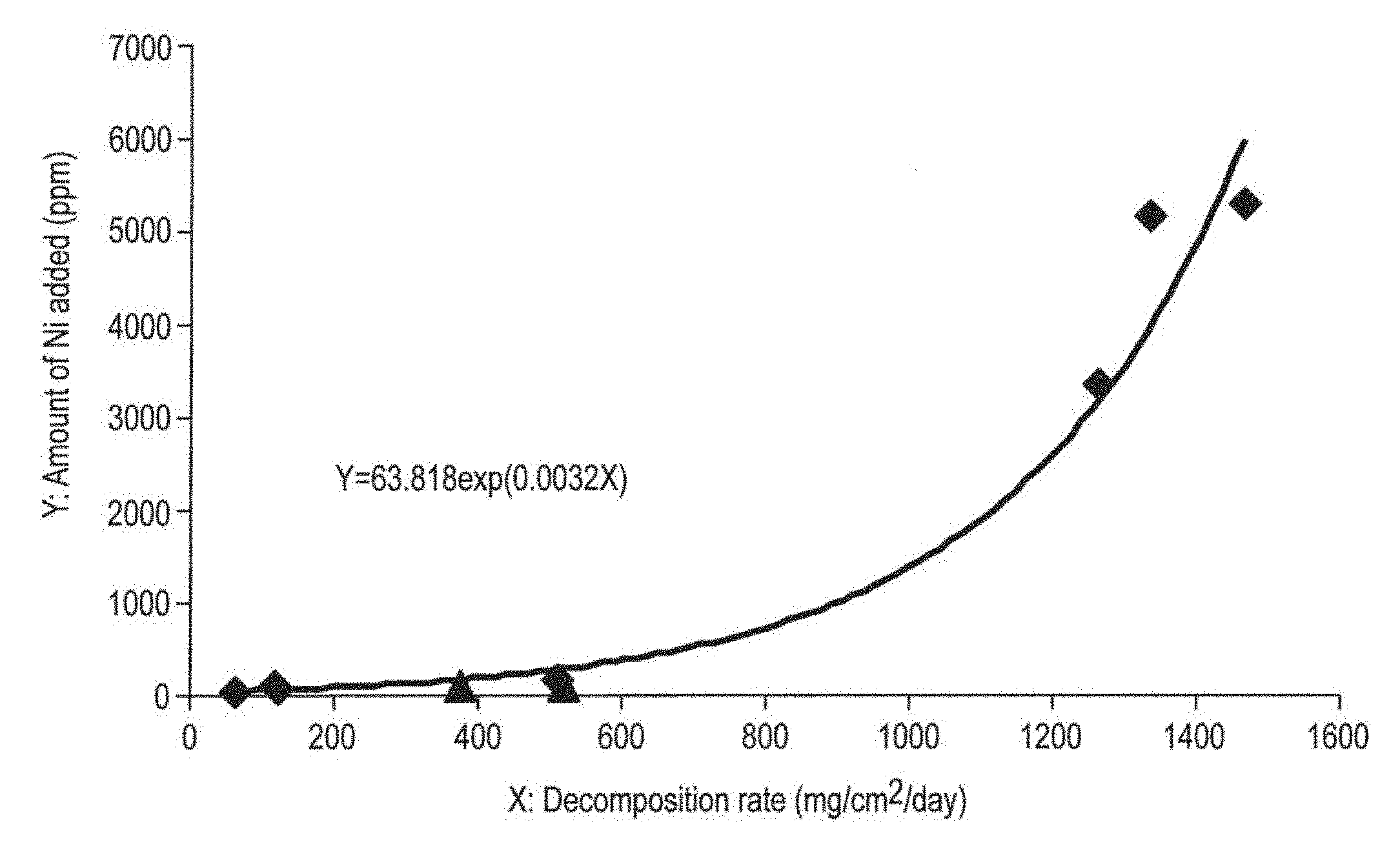
The present invention is a method for producing a magnesium alloy is provided, which is characterized by adding 7.8 to 9.2% by weight of Al, 0.20 to 0.80% by weight of Zn, 0.12 to 0.40% by weight of Mn, and an amount Y [ppm] calculated by formulas provided below, of Ni, (1) when the decomposition rate X is lower than 500 mg/cm.sup.2/day, Y=48.385 Ln(X)-119.64 (Formula 1) (2) when the decomposition rate X is 500 or higher but lower than 1400 mg/cm.sup.2/day, Y=63.818 exp(0.0032X) (Formula 2) and controlling to have a desired decomposition rate.
| Inventors: | MATSUMOTO; Yasunobu; (Takaoka-shi, JP) ; NAKAGAWA; Akira; (Takaoka-shi, JP) ; OGAWA; Masayoshi; (Takaoka-shi, JP) ; SAKAI; Naoto; (Takaoka-shi, JP) ; SHIMIZU; Kazunori; (Takaoka-shi, JP) | ||||||||||
| Applicant: |
|
||||||||||
|---|---|---|---|---|---|---|---|---|---|---|---|
| Family ID: | 62558213 | ||||||||||
| Appl. No.: | 16/442881 | ||||||||||
| Filed: | June 17, 2019 |
Related U.S. Patent Documents
| Application Number | Filing Date | Patent Number | ||
|---|---|---|---|---|
| PCT/JP2016/087674 | Dec 16, 2016 | |||
| 16442881 | ||||
| Current U.S. Class: | 1/1 |
| Current CPC Class: | B21C 23/00 20130101; C22C 23/02 20130101; B21C 23/002 20130101; C22C 1/02 20130101; B22D 21/007 20130101 |
| International Class: | C22C 1/02 20060101 C22C001/02; C22C 23/02 20060101 C22C023/02 |
Claims
1. A method of producing a magnesium alloy characterized by adding: 7.8 to 9.2% by weight of Al, 0.20 to 0.80% by weight of Zn, 0.12 to 0.40% by weight of Mn, and an amount Y [ppm] calculated by formulas provided below, of Ni, (1) when the decomposition rate X is lower than 500 mg/cm.sup.2/day, Y=48.385 Ln(X)-119.64 (Formula 1) (2) when the decomposition rate X is 500 or higher but lower than 1400 mg/cm.sup.2/day, Y=63.818 exp(0.0032X) (Formula 2) and controlling to have a desired decomposition rate.
2. A magnesium alloy controlled to have a desired decomposition rate, characterized by comprising: 7.8 to 9.2% by weight of Al, 0.20 to 0.80% by weight of Zn, 0.12 to 0.40% by weight of Mn, and an amount Y [ppm] calculated by formulas provided below, of Ni, (1) when the decomposition rate X is lower than 500 mg/cm.sup.2/day, Y=48.385 Ln(X)-119.64 (Formula 1) (2) When the decomposition rate X is 500 or higher but lower than 1400 mg/cm.sup.2/day, Y=63.818 exp(0.0032X) (Formula 2).
Description
CROSS-REFERENCE TO RELATED APPLICATIONS
[0001] This application is a Continuation Application of PCT Application No. PCT/JP2016/087674, filed Dec. 16, 2016, the entire contents of which are incorporated herein by reference.
BACKGROUND OF THE INVENTION
1. Field of the Invention
[0002] The invention relate generally to a method of producing a magnesium alloy and the magnesium alloy.
2. Description of the Related Art
[0003] Magnesium alloys are used for various uses because of their advantageous characteristics, for example, as a member which contributes to realization of reducing the weight and a member which improves vibration-damping properties. Moreover, magnesium alloys are used in various fields due to their advantageous characteristics as metal materials of being basic, for example, as a sacrificial electrode member used to prevent corrosion of a structure placed in a soil or sea water, or a civil engineering work member. In recent years, taking advantage of the properties of decomposing in the living body, the applied technology for members for medical treatments, such as stents and plates are being developed.
BRIEF SUMMARY OF THE INVENTION
[0004] However, under various environments or conditions, there is a demand of a magnesium alloy which has performance required as a member to be applied (for example, mechanical properties, such as strength), and still has such properties that it stably dissolves or decomposes in desired time. An object of the present inventions is to provide a method of producing a magnesium alloy controllable to decompose at a desired rate while maintaining predetermined mechanical properties, and such a magnesium alloy.
[0005] The embodiment recited in claim 1 is a method of producing a magnesium alloy is provided, which is characterized by adding: 7.8 to 9.2% by weight of Al, 0.20 to 0.80% by weight of Zn, 0.12 to 0.40% by weight of Mn, and an amount Y [ppm] calculated by formulas provided below, of Ni,
[0006] (1) when the decomposition rate X is lower than 500 mg/cm.sup.2/day,
Y=48.385 Ln(X)-119.64 (Formula 1)
[0007] (2) when the decomposition rate X is 500 or higher but lower than 1400 mg/cm.sup.2/day,
Y=63.818 exp(0.0032X) (Formula 2)
and controlling to have a desired decomposition rate.
[0008] The embodiment recited in claim 2 is a magnesium alloy controlled to have a desired decomposition rate, characterized by comprising: 7.8 to 9.2% by weight of Al, 0.20 to 0.80% by weight of Zn, 0.12 to 0.40% by weight of Mn, and an amount Y [ppm] calculated by formulas provided below, of Ni,
[0009] (1) when the decomposition rate X is lower than 500 mg/cm.sup.2/day,
Y=48.385 Ln(X)-119.64 (Formula 1)
[0010] (2) when the decomposition rate X is 500 or higher but lower than 1400 mg/cm.sup.2/day,
Y=63.818 exp(0.0032X) (Formula 2).
[0011] According to the embodiment of claim 1, a magnesium alloy controlled to have a desired decomposition rate can be produced. The thus produced magnesium alloy, while maintaining a generally required strength, can be dissolved after use to easily vanish.
[0012] According to the embodiment of claim 2, a magnesium alloy controlled to have a desired decomposition rate can be obtained. Such a magnesium alloy, while maintaining a generally required strength, can be dissolved after use to easily vanish.
BRIEF DESCRIPTION OF THE SEVERAL VIEWS OF THE DRAWING
[0013] FIG. 1 is a graph showing a relationship between the decomposition rate of a magnesium alloy and the amount of nickel added.
[0014] FIG. 2 is an expanded graph showing an extracted range of the amount of nickel added from 0 to 600 ppm in FIG. 1.
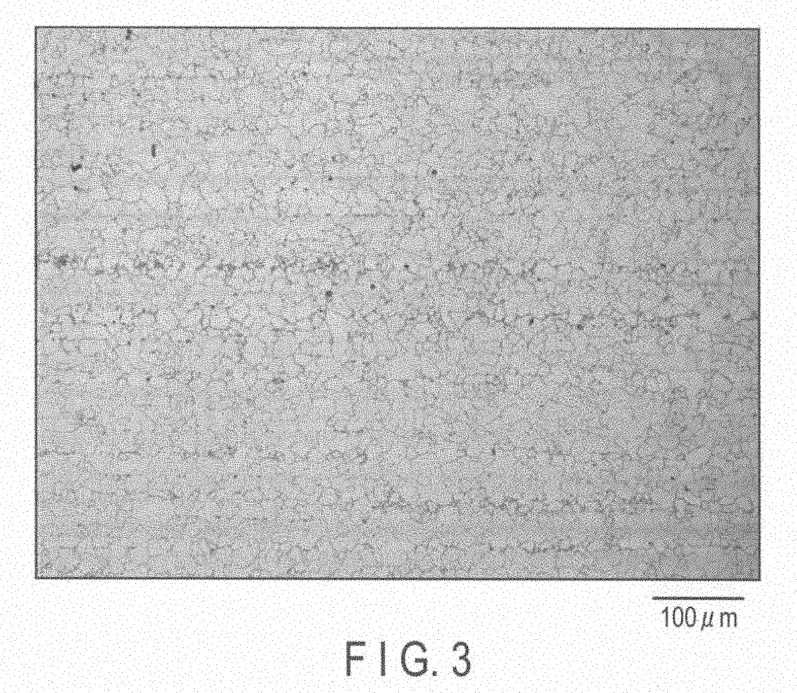
[0015] FIG. 3 is a metallographic microscope photograph of a portion of a magnesium alloy of Experiment 3.
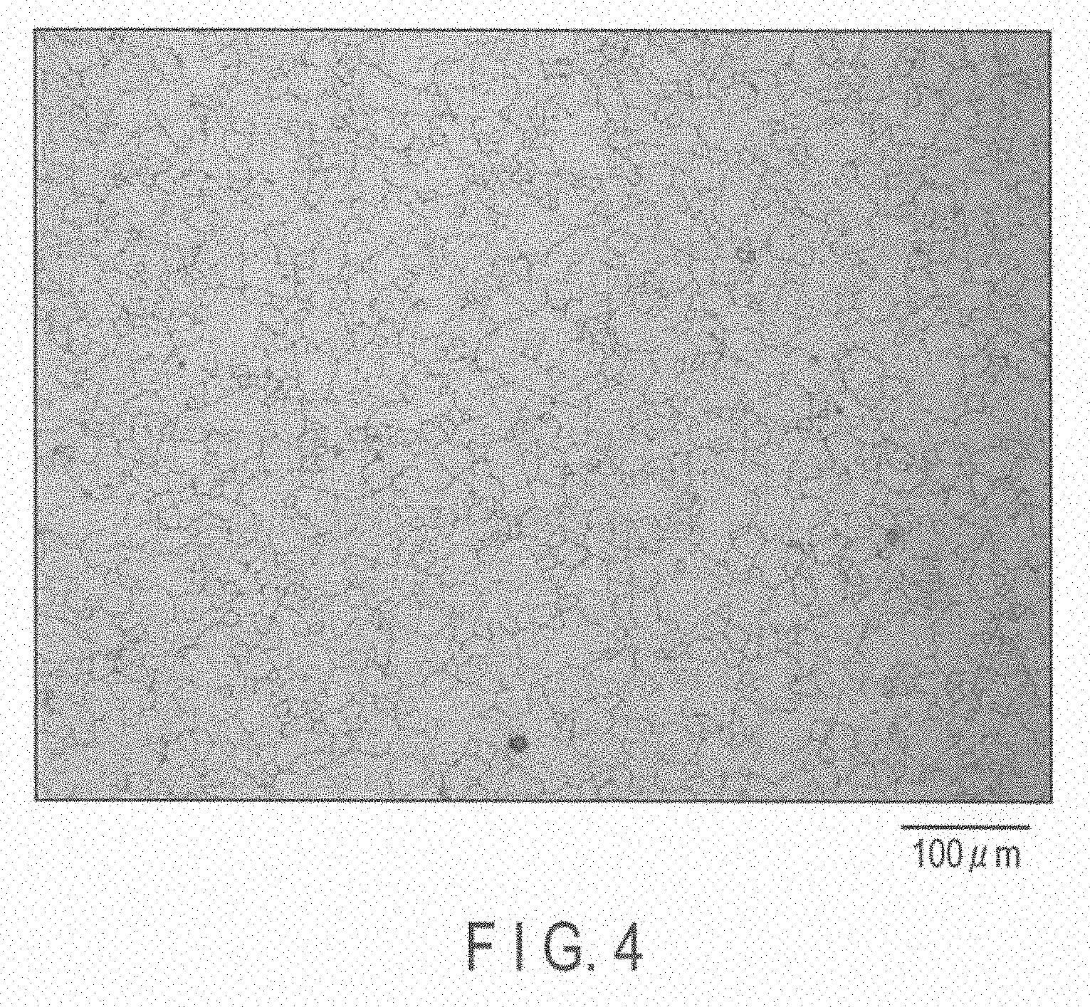
[0016] FIG. 4 is a metallographic microscope photograph of another portion of the magnesium alloy of Experiment 3.
[0017] FIG. 5 is a metallographic microscope photograph of still another portion of the magnesium alloy of Experiment 3.
[0018] FIG. 6 is a metallographic microscope photograph of a magnesium alloy of Experiment 4.
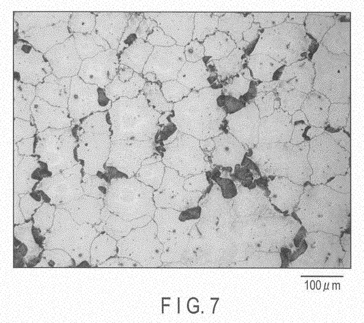
[0019] FIG. 7 is a metallographic microscope photograph of a magnesium alloy of Experiment 8.
[0020] FIG. 8 is a metallographic microscope photograph of a magnesium alloy of Experiment 9.
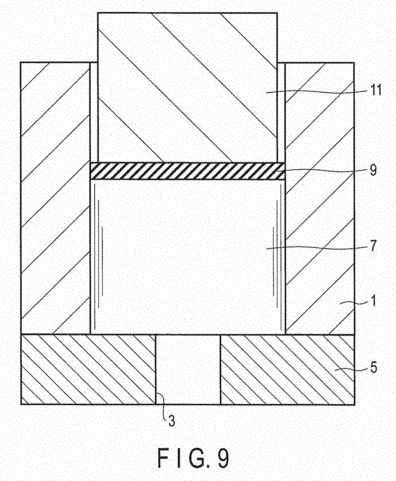
[0021] FIG. 9 is a cross section of a vertical extruder used for hot extrusion processing of the magnesium alloy.
DETAILED DESCRIPTION OF THE INVENTION
[0022] Hereafter, a method of producing a magnesium alloy according to an embodiment will be described in detail.
[0023] In the magnesium alloy production method of the embodiment, 7.8 to 9.2% by weight of Al, 0.20 to 0.80% by weight of Zn, 0.12 to 0.40% by weight of Mn, and an amount Y [ppm] calculated by formulas provided below, of Ni are added, and they are controlled to have a desired decomposition rate [mg/cm.sup.2/day].
[0024] (1) When the decomposition rate X is lower than 500 mg/cm.sup.2/day,
Y=48.385 Ln(X)-119.64 (Formula 1)
[0025] (2) when the decomposition rate X is 500 or higher but lower than 1400 mg/cm.sup.2/day,
Y=63.818 exp(0.0032X) (Formula 2).
[0026] (a) Reason for Setting the Amount of Al to 7.8 to 9.2% by Weight
[0027] When the Al content of the magnesium alloy is up to about 10% by weight, the strength and proof strength of the magnesium alloy improve with the increase in Al content. When the Al content is 10% by weight or more, the extrusion speed of the magnesium alloy significantly decreases. On the other hand, when the Al content is 6.0% by weight or less, precipitation of Mg.sub.17Al.sub.12, which is an intermetallic compound of Mg and Al, is so small in amount that a pinning effect (an effect of suppressing the growth of crystal grains to be able to maintain fine recrystallized grains), cannot be obtained, thereby creating coarse crystal grains.
[0028] For the reasons provided above, the amount of Al is set to 7.8 to 9.2% by weight in order to ensure precipitation of Mg.sub.17Al.sub.12, fineness of the crystal grains achieved thereby, improvement in strength and proof strength, and ensuring extrudability.
[0029] (b) Reason for Setting the Amount of Zn to 0.20 to 0.80% by Weight
[0030] When Zn is added to the magnesium alloy, an effect of improving the proof strength and elongation by solid solution strengthening and promoting the aging precipitation (an effect of precipitating a solid solution or the like with time progress) can be obtained. As the Zn content increases, the tensile strength and proof strength at room temperature improve; however, when the Zn content is excessive, there is a tendency that the toughness and strength decrease.
[0031] Further, based on the experimental results set out below, the amount of Zn is set to 0.20 to 0.80% by weight.
[0032] (c) Reason for Setting the Amount of Mn to 0.12 to 0.40% by Weight
[0033] When Mn is added to the magnesium alloy, an effect of suppressing coarseness of recrystallization and an effect of settling Fe, which is an impurity element, can be obtained, and therefore 0.10% by weight or more of Mn is essential. On the other hand, when the Mn content is excessive, chances are high that the intermetallic compound of Al and Mn becomes coarse, which may give rise to a starting point of fatigue fracture.
[0034] For the reasons provided above, the content of Mn is set to 0.12 to 0.40% by weight.
[0035] (d) Reason for Adding Ni
[0036] Generally, when nickel is added to a magnesium alloy, it becomes easily corrodible; therefore Ni is not added. However, the inventors of the present embodiments carried out numerous experiments, and have found a method of producing a magnesium alloy controlled to have a desired decomposition rate by adjusting the amount of nickel added as indicated by the above-provided formula (1) or (2).
[0037] Hereafter, each experiment will be described with reference to accompanying drawings provided in FIGS. 1 to 9.
[0038] Magnesium alloys were produced and evaluated in Experiments 1 to 9. Note that in the production of the magnesium alloys of Experiments 1 to 9, an AZ-based alloy (Mg--Al--Zn based alloy), AZ80A alloy in the ASTM standard was used as a base metal. This is a magnesium alloy which can contain Al, Zn and Mn in the ranges provided above. The composition ratio of the AZ80A alloy is provided in Table 1 below.
TABLE-US-00001 TABLE 1 Composition ratio of AZ80A alloy Composition ratio (% by weight) Al Zn Mn Si Fe Cu Ni Mg AZ80A alloy 7.8 to 9.2 0.20 to 0.8 0.12 to 0.5 .ltoreq.0.10 .ltoreq.0.005 .ltoreq.0.05 .ltoreq.0.005 Bal.
[0039] For example, the AZ80A alloy of a temper designation of F exhibit mechanical properties of a tensile strength of 295 MPa or higher, a 0.2%-proof strength of 195 MPa or higher, and an elongation of 9% or higher. Note that the temper designation of F indicates a material obtained directly from the manufacturing process which does not include any special adjustment in hardening or heat treatment.
Experiment 1
[0040] An AZ80A alloy was used as the base metal, and 70 ppm of Ni was added thereto. Then, they were melted and subjected to die casting, thus preparing a billet.
[0041] The billet was subjected to a hot extrusion processing described below using a vertical extruder shown in FIG. 9, and thus a magnesium alloy of Experiment 1 was obtained.
[0042] Here, the extrusion processing will be described with reference to FIG. 9. A container 1 and a dice 5 in which a through hole 3 is formed were fixed, and a billet 7 having a diameter of 60 mm and a length of 70 mm was accommodated in the container 1. Next, a fix lock 9 was set on the billet 7, and a stem 11 was set on the fix lock 9. The fix lock 9 was placed to mediate between the billet 7 and the stem 11. Subsequently, the billet 7 was pressurized by the stem 11 at a temperature of 350.degree. C. towards the through hole 3 formed in the dice 5. Then, via the through hole 3, extrusion was carried out at a speed of 0.5 m/min, thereby producing an extruded material having a diameter of 10 mm. Note that in the extrusion, a load of about 400 tons was applied.
Experiment 2
[0043] An AZ80A alloy was used as the base metal, and 100 ppm of Ni was added thereto. Then, they were melted and subjected to die casting, thus preparing a billet.
[0044] The billet was subjected to a hot extrusion processing similar to that of Experiment 1, and thus a magnesium alloy of Experiment 2 was obtained.
Experiment 3
[0045] An AZ80A alloy was used as the base metal, and 120 ppm of Ni was added thereto. Then, they were melted and subjected to die casting, thus preparing a billet.
[0046] The billet was subjected to a hot extrusion processing similar to that of Experiment 1, and thus a magnesium alloy of Experiment 3 was obtained.
Experiment 4
[0047] An AZ80A alloy was used as the base metal, and 180 ppm of Ni was added thereto. Then, they were melted and subjected to die casting, thus preparing a billet.
[0048] The billet was subjected to a hot extrusion processing similar to that of Experiment 1, and thus a magnesium alloy of Experiment 4 was obtained.
Experiment 5
[0049] An AZ80A alloy was used as the base metal, and 3380 ppm of Ni was added thereto. Then, they were melted and subjected to die casting, thus preparing a billet.
[0050] The billet was subjected to a hot extrusion processing similar to that of Experiment 1, and thus a magnesium alloy of Experiment 5 was obtained.
Experiment 6
[0051] An AZ80A alloy was used as the base metal, and 5100 ppm of Ni was added thereto. Then, they were melted and subjected to die casting, thus preparing a billet.
[0052] The billet was subjected to a hot extrusion processing similar to that of Experiment 1, and thus a magnesium alloy of Experiment 6 was obtained.
Experiment 7
[0053] An AZ80A alloy was used as the base metal, and 5300 ppm of Ni was added thereto. Then, they were melted and subjected to die casting, thus preparing a billet.
[0054] The billet was subjected to a hot extrusion processing similar to that of Experiment 1, and thus a magnesium alloy of Experiment 7 was obtained.
Experiment 8 (Comparative Example)
[0055] An AZ80A alloy was used as the base metal, and 120 ppm of Ni was added thereto. Then, they were melted and subjected to die casting, thus preparing a billet.
[0056] To this billet, a hot extrusion processing was not carried out, and thus a magnesium alloy of Experiment 8 was obtained.
Experiment 9 (Comparative Example)
[0057] An AZ80A alloy was used as the base metal, and 140 ppm of Ni was added thereto. Then, they were melted and subjected to die casting, thus preparing a billet.
[0058] To this billet, a hot extrusion processing was not carried out, and thus a magnesium alloy of Experiment 9 was obtained.
[0059] Evaluation 1
[0060] The composition ratio of each of the magnesium alloy of Experiments 1 to 9 was measured based on a high-frequency inductively coupled plasma optical emission spectrometry (ICP optical emission spectrometry). The results of the magnesium alloys of Experiments 1 to 9 in composition ratio are provided in Table 2 below.
TABLE-US-00002 TABLE 2 Composition ratios of magnesium alloys in Experiments 1 to 9 Composition ratio (% by weight) Al Zn Mn Si Fe Cu Ni Mg Experiment 1 9.1 0.64 0.25 0.02 <0.002 <0.002 0.0074 Bal. Experiment 2 8.9 0.60 0.23 0.02 <0.002 <0.002 0.0100 Bal. Experiment 3 8.2 0.56 0.23 0.02 <0.002 <0.002 0.0123 Bal. Experiment 4 8.8 0.59 0.24 0.02 <0.002 <0.002 0.0180 Bal. Experiment 5 7.9 0.58 0.22 0.02 <0.002 <0.002 0.3380 Bal. Experiment 6 8.1 0.59 0.22 0.02 <0.002 <0.002 0.5160 Bal. Experiment 7 7.8 0.52 0.19 0.02 0.001 0.004 0.5300 Bal. Experiment 8 8.2 0.56 0.23 0.02 <0.002 <0.002 0.0123 Bal. (Comparative Example) Experiment 9 8.4 0.61 0.24 0.02 <0.002 <0.002 0.0142 Bal. (Comparative Example)
[0061] Evaluation 2
[0062] The magnesium alloys of Experiments 1 to 9 were immersed in a 2%-KCl solution of 93.degree. C., and the decomposition rates thereof were measured. The results are indicated in Table 3 below.
TABLE-US-00003 TABLE 3 Amount of Ni added and decomposition rate of magnesium alloys Experiments 1 to 9 Amount of Ni added Decomposition rate (ppm) (mg/cm.sup.2/day) Experiment 1 74 58 Experiment 2 100 115 Experiment 3 123 113 Experiment 4 180 501 Experiment 5 3380 1242 Experiment 6 5160 1313 Experiment 7 5300 1441 Experiment 8 123 367 (Comparative Example) Experiment 9 142 507 (Comparative Example)
[0063] Based on the results of Table 3 provided above, a graph was created, in which the results indicated in FIG. 1 were plotted. The correlations between the plots of FIG. 1 mentioned above were analyzed (except for Experiments 8 and 9, which are comparative examples), and as a result, Formula 2, which is an expression indicating the relationship between the amount of nickel added and the decomposition rate was obtained.
[0064] FIG. 2 is an expanded graph extracting the range of the amount of nickel added from 0 to 600 ppm in FIG. 1. In a similar manner to that of FIG. 1, the correlations between the plots of FIG. 2 were analyzed (except Experiments 8 and 9, which are comparative examples), and as a result, Formula 1 was obtained.
[0065] From the above, it can be concluded that in the production of magnesium alloys whose decomposition rate is less than 500 mg/cm.sup.2/day, the amount of nickel added, which corresponds to a desired decomposition rate is calculated using Formula 1, and thus a magnesium alloy controlled to have the desired decomposition rate can be produced. Moreover, in the production of a magnesium alloy having a decomposition rate of 500 or higher but less than 1400 mg/cm.sup.2/day, a magnesium alloy controlled to have a desired decomposition rate can be produced using Formula 2.
[0066] Evaluation 3
[0067] Cross sections of cut Magnesium alloys of Experiments 3, 4, 8 and 9 were observed using a metallographic microscope, and for each case, the crystal grain diameter was measured based on a planimetry of JIS H 0542 (crystal granularity test for magnesium alloy rolled plates). The results are indicated in Table 4 below, and also metallographic microscope photographs are provided.
TABLE-US-00004 TABLE 4 The amount of Ni added, decomposition rate and crystal grain diameter of each of magnesium alloys in experiments 3, 4, 8 and 9 Amount of Decomposition Ni added rate Crystal grain (ppm) (mg/cm.sup.2/day) diameter (.mu.m) Experiment 3 123 113 26, 35, 39 Experiment 4 180 501 15 Experiment 8 123 367 156 (Comparative Example) Experiment 9 142 507 141 (Comparative Example)
[0068] Crystal grain diameters of 26 .mu.m, 35 .mu.m and 39 .mu.m in Experiment 3 shown in Table 4 provided above were measured from metallographic microscope photographs of FIGS. 3, 4 and 5, respectively.
[0069] FIG. 6 is a metallographic microscope photograph showing a cross section of the cut magnesium alloy of Experiment 4, and the crystal grain diameter was 15 .mu.m.
[0070] FIG. 7 is a metallographic microscope photograph showing a cross section of the cut magnesium alloy of Experiment 8, and the crystal grain diameter was 156 .mu.m. The black perlite-like sections are of the Mg.sub.17Al.sub.12 phase, and it can be seen that the phase is unevenly located.
[0071] FIG. 8 is a metallographic microscope photograph showing a cross section of the cut magnesium alloy of Experiment 9, and the crystal grain diameter was 141 .mu.m. As in the case of the magnesium alloy of Experiment 8, the Mg.sub.17Al.sub.12 phase is unevenly located.
[0072] As is clear from Table 4 provided above, a correlation was observed also between the decomposition rate and the crystal grain diameter of the magnesium alloys. More specifically, as compared with the magnesium alloys of Experiments 8 and 9, the magnesium alloys of Experiments 3 and 4, which had smaller crystal grain diameters, exhibited low values in the decomposition rate as well.
[0073] (I) Relationship Between Decomposition Rate and Crystal Grain Diameter
[0074] Magnesium alloys having an Al content of 6% by weight or more, such as of Experiments 1 to 9 consist of a chemically unstable matrix phase, an Mg.sub.17Al.sub.12 phase, which is an intermetallic compound phase which contains a great amount of Al, which is chemically stable, and an Al--Mn phase.
[0075] In such magnesium alloys, progress of decomposition is promoted preferentially from a chemically unstable matrix phase. The progress of decomposition depends on the Mg.sub.17Al.sub.12 phase precipitates to surround crystal grain boundaries mainly. Therefore, the finer the grains are, the more stably, the decomposition becomes controllable.
[0076] On the other hand, as the grains of a magnesium alloy are larger, the more coarsely and unevenly Mg.sub.17Al.sub.12 precipitates, and thus the decomposition rate increases and further it is very much likely that the decomposition rate varies greatly. Therefore, it is difficult to control the decomposition rate.
[0077] As described above, from the view point of stable control of the decomposition rate, it is desirable that the grains of the magnesium alloy be finer in order to distribute the Mg.sub.17Al.sub.12 phase more uniformly. It can be seen from the metallographic microscope photograph of FIG. 5 that the maximum crystal grain diameter of the magnesium alloy of Experiment 3 is 100 .mu.m. On the other hand, the crystal grain diameter of the magnesium alloy of Experiment 4 is 15 .mu.m. Here, as is clear from the results of Experiment 3 indicated in Table 4 provided above, the size of grains varies from one cut section to another, and thus the crystal grain diameter may be 10 .mu.m in some other section. Therefore, the crystal grain diameter of the magnesium alloy should desirably be, 10 to 100 .mu.m, to be specific. Note that the maximum crystal grain diameter described above is meant an arithmetical average of the maximum diameter and the minimum diameter of the largest crystal grain in the metallographic microscope photograph of FIG. 5.
[0078] The Mg.sub.17Al.sub.12 phase preferentially precipitates discontinuously in crystal grain boundaries after dynamic recrystallization occurs in such a magnesium alloy in the process of cooling. Therefore, the finer the grains, the higher the possibility that they are distributed even more uniformly in crystal grain boundaries. Moreover, as the chemically unstable matrix phases become more equal to each other in a fixed size, the variation in decomposition rate can be reduced for control. In consideration of the above, the crystal grain diameter of the magnesium alloy should desirably be 10 to 50 .mu.m, in which they cannot easily form duplex grains.
[0079] (II) Relationship Between Crystal Grain Diameter and Extrusion
[0080] In the magnesium alloys, the crystal grain diameters are made finer by extrusion, and also Mg.sub.17Al.sub.12 precipitates, thus securing the strength of the extruded material. With a great amount of precipitation of Mg.sub.17Al.sub.12, the growth of the crystal grains of the magnesium alloy is suppressed, thus making it possible to maintain fine recrystallized grains.
[0081] Evaluation 4
[0082] The magnesium alloys of Experiments 1, 2, 4 and 7 were subjected to tension test at room temperature to measure mechanical properties, tensile strength, 0.2%-proof strength, and elongation. The tension test was carried out after shaping the magnesium alloys each into that of No. JIS14A test sample piece, at a speed of an initial strain rate (1.times.10.sup.-3[s.sup.-1]) at room temperature. The results of the mechanical properties of the magnesium alloys of Experiments 1, 2, 4 and 7 are indicated in Table 5 below.
TABLE-US-00005 TABLE 5 Mechanical properties of magnesium alloys of Experiments 1, 2, 4 and 7 0.2%-proof Tensile strength strength Elongation (MPa) (MPa) (%) Experiment 1 334 223 10 Experiment 2 340 235 9 Experiment 4 337 219 11 Experiment 7 322 213 18
[0083] As is clearly from Table 5 provided above, the magnesium alloys of the experiments exhibit a tensile strength of 320 MPa or higher, a 0.2%-proof strength of 210 MPa or higher, and an elongation of 9% or higher, and thus have a strength which satisfies the mechanical properties of the AZ80A alloy in the ASTM standards.
[0084] As described above, the magnesium alloys according to the embodiments, such as of those of Experiments 1 to 9, can be dissolved after use and easily vanished. These magnesium alloys can be dissolved and vanished at a desired decomposition rate in accordance with any environment to be employed.
[0085] The present invention is not limited to the above-described embodiments, but can be modified in various ways in a range which it does not fall out of the essence of the invention.
[0086] For example, in the above-described experiments, the magnesium alloys were prepared from an AZ80A alloy as the base metal, but MB3 or MS3, as well, of JIS standards can be used as a base metal. The MB3 and MS3 are magnesium alloys which may contain Al, Zn and Mn in the ranges described above, and the composition ratios of MB3 and MS3 are indicated in Table 6 below.
TABLE-US-00006 TABLE 6 Composition ratios of MB3 and MS3 Composition ratio (% by weight) Al Zn Mn Si Fe Cu Ni Others Mg MB3, MS3 7.5 to 9.2 0.2 to 1.0 0.10 to 0.40 .ltoreq.0.10 .ltoreq.0.005 .ltoreq.0.05 .ltoreq.0.005 .ltoreq.0.30 Bal.
* * * * *
D00000
D00001
D00002
D00003
D00004
D00005
D00006
D00007
D00008
D00009
XML
uspto.report is an independent third-party trademark research tool that is not affiliated, endorsed, or sponsored by the United States Patent and Trademark Office (USPTO) or any other governmental organization. The information provided by uspto.report is based on publicly available data at the time of writing and is intended for informational purposes only.
While we strive to provide accurate and up-to-date information, we do not guarantee the accuracy, completeness, reliability, or suitability of the information displayed on this site. The use of this site is at your own risk. Any reliance you place on such information is therefore strictly at your own risk.
All official trademark data, including owner information, should be verified by visiting the official USPTO website at www.uspto.gov. This site is not intended to replace professional legal advice and should not be used as a substitute for consulting with a legal professional who is knowledgeable about trademark law.