Fluid-controlled Wire Tension Mechanism
Chen; Shun-Tong ; et al.
U.S. patent application number 16/131602 was filed with the patent office on 2019-10-03 for fluid-controlled wire tension mechanism. The applicant listed for this patent is National Taiwan Normal University. Invention is credited to Yen-Chia Chang, Shun-Tong Chen, Ying-Dan Chen, Jia-Jin Zhong.
| Application Number | 20190300324 16/131602 |
| Document ID | / |
| Family ID | 65432003 |
| Filed Date | 2019-10-03 |


| United States Patent Application | 20190300324 |
| Kind Code | A1 |
| Chen; Shun-Tong ; et al. | October 3, 2019 |
FLUID-CONTROLLED WIRE TENSION MECHANISM
Abstract
The present invention relates to a fluid-controlled wire tension mechanism including a sealed container, a control valve, and a delivery spool. The sealed container has a space. The control valve is coupled to the sealed container to control fluid pressure in the space. The delivery spool is coupled to the sealed container with a compression end and a reel. The compression end is placed in the space, and the reel is located outside the sealed container to send out a cutting wire. Wherein, a fluid enters the space and applies pressure on the compression end. The present invention utilizes the fluid pressure to produce the rotating impedance to the delivery spool, so that the component is wear-proof, the line tension is easily controlled and the stream of the cutting wire can be stable for a long time. Therefore, the cutting effect and the shape are more precise.
| Inventors: | Chen; Shun-Tong; (Taipei City, TW) ; Chen; Ying-Dan; (Taipei City, TW) ; Zhong; Jia-Jin; (Taipei City, TW) ; Chang; Yen-Chia; (Taipei City, TW) | ||||||||||
| Applicant: |
|
||||||||||
|---|---|---|---|---|---|---|---|---|---|---|---|
| Family ID: | 65432003 | ||||||||||
| Appl. No.: | 16/131602 | ||||||||||
| Filed: | September 14, 2018 |
| Current U.S. Class: | 1/1 |
| Current CPC Class: | B65H 2701/36 20130101; B65H 59/04 20130101; B65H 59/381 20130101; B65H 2406/00 20130101; B65H 59/38 20130101 |
| International Class: | B65H 59/04 20060101 B65H059/04; B65H 59/38 20060101 B65H059/38 |
Foreign Application Data
| Date | Code | Application Number |
|---|---|---|
| Mar 30, 2018 | TW | 107111264 |
Claims
1. A fluid-controlled wire tension mechanism, adapted to control a tension of a cutting wire by adjusting a fluid pressure generated by a fluid, comprising: a sealed container, having a space for containing the fluid; a control valve, coupled to the sealed container to adjust the fluid pressure in the space; and a delivery spool, coupled to the sealed container, the delivery spool having a compression end and a reel, the compression end being configured in the space and linked with the reel, and the reel being configured outside of the sealed container to send the cutting wire; wherein the tension of the cutting wire is controlled by a fluid damping force corresponding to the fluid pressure applied to the compression end.
2. The fluid-controlled wire tension mechanism of claim 1, wherein the fluid is liquid or gas, and the cutting wire is a metal wire.
3. The fluid-controlled wire tension mechanism of claim 1, further comprising a disk configured on the compression end of the delivery spool to bear the fluid pressure.
4. The fluid-controlled wire tension mechanism of claim 1, further comprising a collecting spool configured to receive the cutting wire, wherein delivery spool is configured to control the tension of the cutting wire, and the collecting spool is configured to control a move speed of the cutting wire.
5. The fluid-controlled wire tension mechanism of claim 1, wherein the cutting wire is wound on the reel, and the reel is detachably coupled to the compression end.
6. The fluid-controlled wire tension mechanism of claim 1, wherein the sealed container further comprises a diversion hole, and the fluid flows into the space via the diversion hole.
7. The fluid-controlled wire tension mechanism of claim 6, wherein the sealed container further comprises an O-ring, a sealing cap and a sealing housing, the sealing housing has the diversion hole; the sealing cap and the sealing housing are sealed by the O-ring to form the space.
8. The fluid-controlled wire tension mechanism of claim 7, wherein the sealed container further comprises a bearing, and the delivery spool is coupled to the sealing cap by the bearing.
9. The fluid-controlled wire tension mechanism of claim 1, further comprising a plurality of delivery spools, wherein the plurality of delivery spools are parallel to each other to form a array, and each of the plurality of delivery spools sends a corresponding cutting wire and controls the tension of the corresponding cutting wire.
10. The fluid-controlled wire tension mechanism of claim 1, wherein the control valve is configured to control a total amount of the fluid in the space, an inflow rate of the fluid into the space, an inflow pressure of the fluid into the space, or a volume of the space.
Description
CROSS-REFERENCE TO RELATED APPLICATIONS
[0001] This application claims the priority benefit of Taiwan Application Serial No. 107111264 filed Mar. 30, 2018 the disclosure of which is incorporated herein by reference.
BACKGROUND OF THE INVENTION
Field of the Invention
[0002] The present invention relates to a wire tension control mechanism, and more particularly, to a non-contact wire tension control mechanism which controls the wire tension by adjusting the fluid pressure.
Description of the Prior
[0003] In recent years, with advances in technologies such as semiconductor, electronic industry, and machinery, most products have been developed to be small and refined. In particular, products in semiconductor industry, display industry, digital content industry and biotechnology industry are all developed toward miniaturization. Industry is in great demand for light, thin, short, and small components such as precision molds, fixtures, cutters, tools, jigs, and probes. The materials used for manufacturing also tend to be selected as hard-to-cut materials, such as tungsten, conductive ceramics, boron-doped polycrystalline composite diamonds, and boron-doped monocrystalline diamonds. All the above requirements can be solved by wire electrical discharge machining (WEDM). That is to say, there is a large market in WEDM field.
[0004] In WEDM technology, the wire tension control is one of the important parameters. The wire tension not only affects the details of the cutting structure and the precision of the machining, but also affects whether the wire electrode is broken. In practice, most of the wire electrodes are used with wheel brake system to control the wire tension. However, it is difficult for the wheel brake system to make little adjustment and control. In addition, since the electrical discharge wire electrode needs to be directly contacted with the wheel brake system, the tension of the wire electrode is difficult to be stably controlled due to the influence of the dynamic material friction coefficient.
[0005] A non-contact control method uses a permanent magnet instead of the wheel brake system used in the contact control method. The wire tension is controlled by adjusting the distance between the permanent magnet and the wire electrode spool. However, the adjustment range of the distance is limited, and the wire tension cannot be accurately controlled. Furthermore, if there are multiple wire electrodes needed to be simultaneously operated for high-efficiency cutting, it is difficult to adjust a plurality of wire tensions of the wire electrodes arranging in an array. Additionally, the hysteresis phenomena may occur to make the wire flow unstable when the wire tension is controlled by the permanent magnet.
[0006] Therefore, a new tension control system is needed to replace the tension control system which has a wheel brake system or a permanent magnet.
SUMMARY OF THE INVENTION
[0007] In response to the above-mentioned problems, the present invention provides a fluid-controlled wire tension mechanism that applies pressure on a delivery spool to generate a rotational resistant on the delivery spool, wherein the delivery spool is configured to send the cutting wire. Under the fixed wire receiving speed conditions, the appropriate tension of the cutting wire can be obtained by controlling the magnitude of the pressure that the fluid applied on the delivery spool.
[0008] The present invention provides a fluid-controlled wire tension mechanism to control a tension of a cutting wire by adjusting a fluid pressure generated by a fluid. The fluid-controlled wire tension mechanism comprises a sealed container, a control valve, and a delivery spool. The sealed container has a space for containing the fluid. The control valve is coupled to the sealed container to adjust the fluid pressure in the space. The delivery spool is coupled to the sealed container, wherein the delivery spool has a compression end and a reel. The compression end is configured in the space and linked with the reel, and the reel is configured outside of the sealed container to send the cutting wire. Wherein the tension of the cutting wire is controlled by a fluid damping force corresponding to the fluid pressure applied to the compression end.
[0009] In an embodiment, the fluid is liquid or gas, and the cutting wire is a metal wire.
[0010] Additionally, the reel is coupled to the cutting wire and linked with the compression end for coupling or winding the cutting wire.
[0011] Furthermore, the reel is detachably coupled to the compression end.
[0012] In an embodiment, the sealed container further comprises a diversion hole, a bearing, a sealing cap, an O-ring and a sealing housing. The sealing cap has the diversion hole, and the diversion hole is used to make the fluid to flow into the space. The sealing cap and the sealing housing are sealed by the O-ring to form the space, and the delivery spool is coupled to the sealing cap by the bearing.
[0013] In one embodiment, the fluid-controlled wire tension mechanism further comprises a disk, and the disk is configured on the compression end of the delivery spool to bear the fluid pressure.
[0014] Besides, the fluid-controlled wire tension mechanism further comprises a collecting spool configured to receive the cutting wire which the reel of the delivery spool sends.
[0015] In addition, the delivery spool is configured to control the tension of the cutting wire, and the collecting spool is configured to control a move speed of the cutting wire.
[0016] In an embodiment, the fluid-controlled wire tension mechanism further comprises a plurality of delivery spools. The plurality of delivery spools are parallel to each other to form an array, and each of the plurality of delivery spools sends a corresponding cutting wire and controls the tension of the corresponding cutting wire.
[0017] Wherein, the control valve is configured to control a total amount of the fluid in the space, an inflow rate of the fluid into the space, an inflow pressure of the fluid into the space, or a volume of the space.
[0018] As mentioned above, the present invention utilizes a fluid to apply pressure on a delivery spool to generate a rotational resistant on the delivery spool, wherein the delivery spool is configured to send a cutting wire. Under the constant receive rate of the collecting spool, the delivery spool is bearing a fluid damping force whose direction is opposite to the wire sending direction. The damping effect on the delivery spool is more pronounced while the fluid pressure increases. Therefore, as the fluid pressure increases, the tension of the cutting wire will become larger, and the cutting wire will also be straighter. Since the fluid pressure does not directly act on the cutting wire, the cutting wire can be maintained in a stable flow, and the tension of the cutting wire can be easily grasped and controlled. Because the fluid-controlled wire tension mechanism of the present invention does not use the friction of the solid contact to generate resistance, the component of the wire tension control mechanism is less prone to wear. Therefore, the fluid-controlled wire tension mechanism of the present invention can maintain stable transmission of the cutting wire for a long time, and the cutting shape can be also more precise.
BRIEF DESCRIPTION OF THE APPENDED DRAWINGS
[0019] Some of the embodiments will be described in detail, with reference to the following figures, wherein like designations denote like members, wherein:
[0020] FIG. 1 shows a perspective view of one embodiment of the fluid-controlled wire tension mechanism in the present invention.
[0021] FIG. 2 shows a schematic view of one embodiment of the fluid-controlled wire tension mechanism in the present invention.
[0022] FIG. 3 shows a schematic view of one embodiment of the delivery spool in the present invention.
[0023] FIG. 4 shows another view of the schematic view of one embodiment of the delivery spool in the present invention.
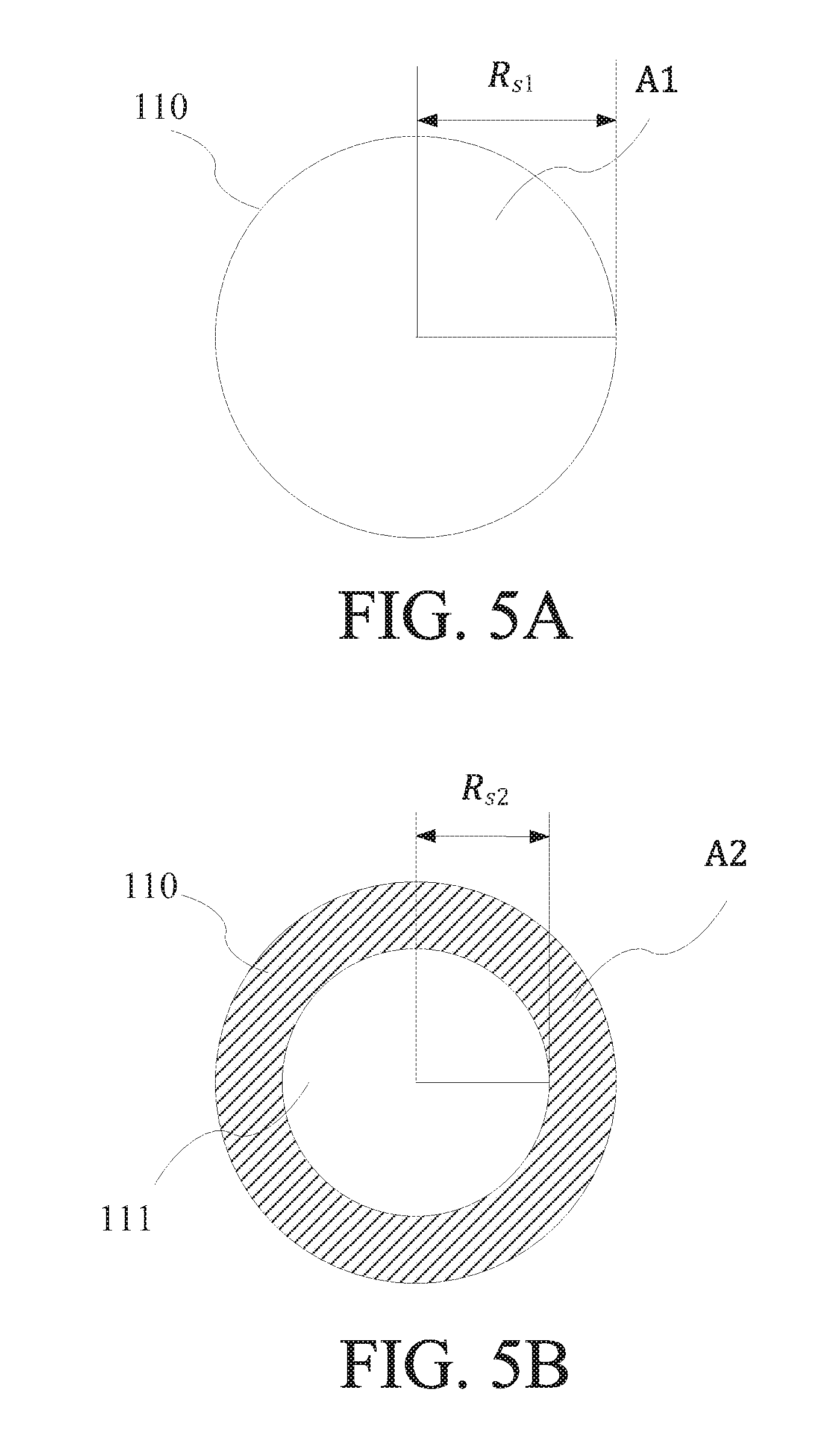
[0024] FIG. 5A shows a schematic view of the compression end as viewed from the end away from the drive shaft.
[0025] FIG. 5B shows a schematic view of the compression end as viewed from the end close to the drive shaft.
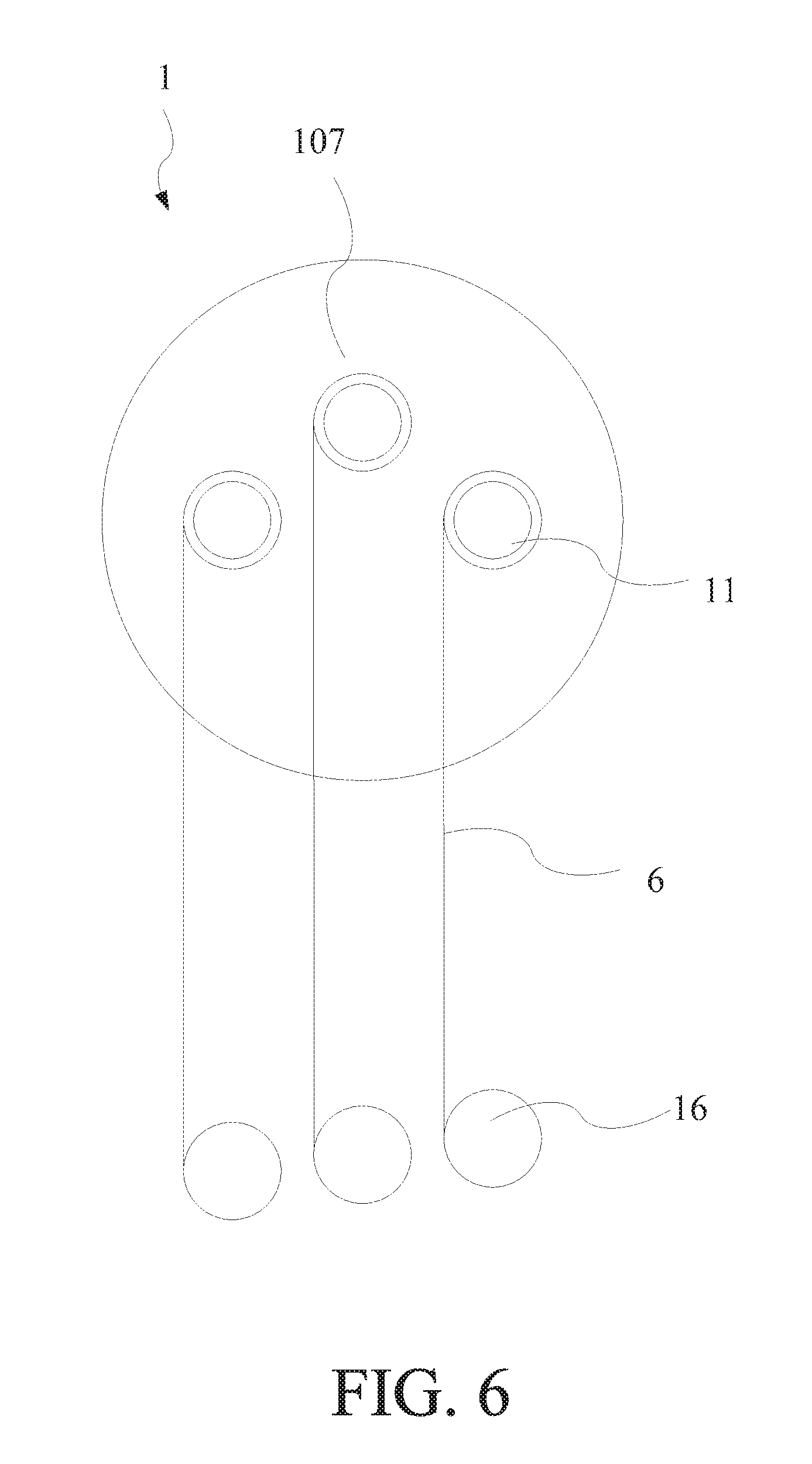
[0026] FIG. 6 shows a schematic view of another embodiment of the fluid-controlled wire tension mechanism in the present invention.
[0027] The advantages, spirits, and features of the present invention will be explained and discussed with embodiments and figures as follows.
DETAILED DESCRIPTION OF THE INVENTION
[0028] A detailed description of the hereinafter described embodiments of the disclosed apparatus and method are presented herein by way of exemplification and not limitation with reference to the Figures. Although certain embodiments are shown and described in detail, it should be understood that various changes and modifications can be made without departing from the scope of the appended claims. The scope of the present invention will in no way be limited to the number of constituting components, the materials thereof, the shapes thereof, the relative arrangement thereof, etc., and are disclosed simply as an example of embodiments of the present invention.
[0029] In the description of the present specification, the terminologies "in an embodiment", "in another embodiment", or "in some embodiments" mean that the specific feature, structure, material or characteristic of the present embodiment is involved in at least one embodiment of the present invention. In the description of the present specification, the schematic representation of the mentioned terminologies does not necessarily refer to the same embodiment. Furthermore, the described specific feature, structure, material or characteristic can be involved in any one or more embodiments in a proper way.
[0030] In the embodiments of the present specification, the terminology "or" includes the combination of part of the listed components, and the combination of all the listed components. For example, the described "A or B" includes only A, only B, and both A and B. Moreover, the terminologies "a" and "the" before the element or component of the present invention do not limit the number of elements or components. Therefore, the terminologies "a" and "the" should be read as "including one" or "at least one". Besides, the singular form of the elements or components also includes the plural form, unless the number clearly refers to the singular form.
[0031] Please refer to FIG. 1 and FIG. 2. FIG. 1 shows a perspective view of one embodiment of the fluid-controlled wire tension mechanism 1 in the present invention. FIG. 2 shows a schematic view of one embodiment of the fluid-controlled wire tension mechanism 1 in the present invention. The fluid-controlled wire tension mechanism 1 in the present invention is used to control a tension of the cutting wire 6 by adjusting a fluid pressure generated by a fluid. The fluid-controlled wire tension mechanism 1 comprises a sealed container 10, a control valve 15, and a delivery spool 11. The sealed container 10 has a space 100 for containing the fluid. The control valve 15 is coupled to the sealed container 10 to adjust the fluid pressure in the space 100. The delivery spool 11 is coupled to the sealed container 10, wherein the delivery spool 11 has a compression end 110 and a reel 116. The compression end 110 is configured in the space 100 and linked with the reel 116, and the reel 116 is configured outside of the sealed container 10 to send the cutting wire 6. Wherein the tension of the cutting wire 6 is controlled by a fluid damping force corresponding to the fluid pressure applied to the compression end 110.
[0032] The fluid pressure in the space 100 will be generated after the fluid enters the space 100. At that time, the compression end 110 in the space 100 will bear the fluid pressure. When the reel 116 rotates for sending the cutting line 6, the compression end 110 will be rotated in synchronization. In addition, the compression end 110 will be affected by a rotational resistant generated by the fluid pressure when the compression end 110 rotates, which will take the other end of the delivery spool 11, such as the reel 116, to slow down the rotational speed. Therefore, a pulling force is generated, wherein the direction of the pulling force is opposite to the direction of sending cutting wire 6. Finally, since the moving speed of the cutting wire 6 does not change, the tension of the cutting wire 6 becomes large.
[0033] The fluid pressure and the rotational resistance applied on the compression end 110 will become larger when the control value 15 is adjusted to increase the fluid pressure in the space 100, which will apply a stronger pulling force on the reel, thereby increasing the tension of the cutting wire 6. Oppositely, the tension of the cutting wire will be reduced when the control value 15 reduces the fluid pressure in the space 100. In one embodiment, the control value 15 controls the fluid pressure in the space 100 by keeping the fluid entering the space. In this case, the sealed container 10 may have a fluid outlet for the fluid to flow out, thereby adjusting the fluid pressure in the sealed container, wherein the fluid outlet may also have an adjustment function. In another embodiment, the control value 15 increases the pressure in the space 100 via a pressurizing device.
[0034] However, the present invention is not limited thereto, wherein the purpose of the control valve 15 is to control the fluid pressure in the space 100. The control valve 15 is capable of achieving this purpose, for example, controlling the total amount of the fluid in the space, controlling the inflow rate when the fluid enters the space, controlling the inflow pressure when the fluid enters the space, controlling the volume in the space, or achieving more than one of above various functions at the same time, which is all within the scope of the present invention.
[0035] In one embodiment, the fluid is liquid, gel, or gas, and the cutting wire 6 is a metal wire. The liquid can be water. Solid or gaseous substances may also be added to the liquid to increase or decrease the fluid damping constant. The solid substances can be selected as sand or dust. The gel state fluid can be paste. The gas can be air, and the metal wire can be a common wire used in cutting process, such as copper wire or zinc wire.
[0036] Addition, the reel 116 can be regarded as a wire bobbin wound with a sufficient amount of metal wire, whereby the cutting wire 6 used for processing is all derived from the reel 116. Furthermore, the reel 116 is detachably coupled to the compression end 110. When the reel 116 sends out all the cutting wire 6 thereon, the reel 116 can be removed to replace a new reel 116. Alternatively, a wire feeding device cooperates with the reel 116, and a metal wire sent by the wire feeding device is attached or wound on the reel 116. Therefore, the delivery spool 11 can be regarded as an element which sends the metal wire and generates a resistant by the fluid pressure.
[0037] In one embodiment, the sealed container 10 further comprises a diversion hole 106 and a sealing cap 107. The diversion hole 106 is used to make the fluid to flow into the space. In one embodiment, the control valve 15 is coupled to the diversion hole 106 or configured outside of sealed container and corresponding to the diversion hole 106, wherein the control valve 15 can easily control the inflow rate of the fluid into the sealed container 10 and the fluid pressure in the sealed container 10. In another embodiment, a valve is external coupled to the diversion hole 106 to adjust the amount of the fluid into and out of the sealed container 10, and the control valve 15 is used to control the fluid pressure in the sealed container 10.
[0038] Additionally, the sealed container 10 includes a bearing 103, and the delivery spool 11 is coupled to the sealing cap 107 by the bearing 103. The reel 116 and the compression end 110 are respectively located on both sides separated by the sealing cap 107 and the bearing 103; therefore, the reel 116 located outside of the sealed container 10 will not directly bear the fluid pressure in the sealed container 10. Further, since the reel 116 is located outside of the sealed container 10, the reel 116 can be easily replaced, and the cutting wire wound on the reel 116 also can be replaced directly. Moreover, the sealed container 10 includes an oil seal 104. The oil seal 104 couples to the sealed cap 107 and surrounds the delivery spool 11. The oil seal 104 is served to prevent fluid from entering or escaping the space 100 via the joint between the delivery spool 11, the bearing 103, and sealed cap 107.
[0039] In addition, the sealed container 10 further comprises an O-ring 109 and a sealing housing 108. The sealing housing 108 has a diversion hole 106, and the sealing cap 107 and the sealing housing 108 are sealed by the O-ring 109 to form the space 100. The sealing cap 107 and the sealing housing 108 can be detachably coupled, so that the component of the compression end 100 in the space 100 can be easily replaced. Furthermore, since the sealing cap 107 is detachably coupled to the sealing housing 108, other components can be added in the sealing housing 108, and also can be replaced with the sealing housing 108 of different capacities to create different geometries of the space. In an embodiment, the geometric size of the space 100 also can be controlled by the control valve 15. Besides, the whole or any part of the control valve 15 may be located in the space 100 to adjust the geometric size of the space 100.
[0040] Please refer to FIG. 3, FIG. 4, FIG. 5A and FIG. 5B. FIG. 3 shows a schematic view of one embodiment of the delivery spool 11 in the present invention. FIG. 4 shows another view of the schematic view of one embodiment of the delivery spool 11 in the present invention. FIG. 5A shows a schematic view of the compression end 110 as viewed from the end away from the drive shaft 111. FIG. 5B shows a schematic view of the compression end 110 as viewed from the end close to the drive shaft 111. In one embodiment, the compression end 110 is formed as a disk shape. But in another embodiment, the fluid-controlled wire tension mechanism 1 further comprises a disk configured on the compression end 110 of the delivery spool 11, wherein the disk is configured to bear the fluid pressure. The area of the disk larger causes the damping force applied on the disk larger. The compression end 110 of the delivery spool 11 is connected and linked with the reel 116 by a drive shaft 111.
[0041] In another embodiment, the compression end 110 is configured with the non-disk shape object, such as another shaped object, an object with blade, or an object with rough surface.
[0042] The compression end 110 in FIG. 5A and FIG. 5B can be a compression end 110 with a disk shape, or a compression end 110 configured with a disk. The total surface area of the compression end 110 should be known before calculating the fluid damping force. In the case of which the diameters of both sides of the disk are the same and the thickness is uniform, the first area A1 is the area of the first surface of the disk, and the second area A2 is the area exposed by the second surface of the disk corresponding to the first surface. The third area A3 is a side surface area of the disk. The total surface area A is the sum of the first area A1, the second area A2, and the third area A3. The first area A1 is .pi..times.R.sub.s1.sup.2 in FIG. 5A, and the second area A2 covered by the oblique line is .pi..times.(R.sub.s1.sup.2-R.sub.s2.sup.2) in FIG. 5B. Therefore, the total surface area which contacts the fluid is
A=.pi.(2R.sub.s1.sup.2-R.sub.s2.sup.2)+2.pi.R.sub.s1t.sub.s
[0043] Wherein, A is the total surface area (mm.sup.2) of the compression end 110, R.sub.s1 is the disk radius (mm) of the compression end 110, R.sub.s2 is the shaft radius (mm) of the drive shaft 111, and is t.sub.s the thickness (mm) of the disk of the compression end 110. In another embodiment, the surface of the portion drive shaft in the space 100 must also be added to the total surface area A.
[0044] Then calculating the fluid damping force applied on the disk according to the total surface area A. The formula is as follows:
F.sub.d=.mu..times.P.times.A
[0045] Wherein, F.sub.d is the fluid damping force (N), .mu. is the fluid damping constant, and P is the fluid pressure (MPa).
[0046] A pulling force applied on the cutting wire 6 is generated by the fluid damping force, that is, the fluid damping force generates a force applied on the reel 116 whose direction is opposite to the wire sending direction. The greater fluid pressure, the greater fluid damping force is generated. At that time, the torque generated by the radius and the wire tension of the reel 116 is equal to the torque generated by the radius of the delivery spool 11 and the damping force, as shown in the following formula:
F.sub.d.times.R.sub.s1=(T.sub.w-F.sub.f).times.R.sub.b
[0047] Wherein, F.sub.d is the fluid damping force (N) calculated above, T.sub.w is the tension of the cutting wire 6, F.sub.f is the bearing rotational friction force of the fluid-controlled wire tension mechanism 1, and R.sub.b is radius of the reel 116. Therefore, the tension of the cutting wire can be calculated by the known fluid damping force, the radius of the disk of the compression end 110, the radius of the coil portion 116, and the friction force of the fluid-controlled wire tension mechanism 1.
[0048] Please refer to FIG. 1 and FIG. 6. FIG. 6 shows a schematic view of another embodiment of the fluid-controlled wire tension mechanism in the present invention. In one embodiment, the fluid-controlled wire tension mechanism 1 further comprises a collecting spool 16 configured to receive the cutting wire 6 sent from the reel 116 of the delivery spool 11. Wherein, the delivery spool 11 is configured to control the tension of the cutting wire 6, and the collecting spool 16 is configured to control a move speed of the cutting wire 6.
[0049] In one embodiment, the fluid-controlled wire tension mechanism 1 further comprises a plurality of delivery spools 11. The plurality of delivery spools 11 are parallel to each other to form an array, and each of the plurality of delivery spools 11 sends a corresponding cutting wire 6 and controls the tension of the corresponding cutting wire 6, wherein there are a plurality of collecting spools 16 for receiving the corresponding cutting wire 6. Further, since the plurality of delivery spools 11 are coupled to a single sealed container 10, the sufficient fluid damping force can be applied on each delivery spool without external amount or pressure of the fluid. Therefore, the present invention can achieve the effect of reducing energy consumption. In another embodiment, one collecting spool 16 can be used to receive a plurality of cutting wire sent from the plurality of delivery spools 11.
[0050] In one embodiment, if each cutting wire 6 has different tension requirements, the disks with different areas can be configured on the corresponding compression end 110 respectively, or the compression end 110 can be directly replaced with different geometries, thereby achieving the effect of different wire tension formed by a single control valve.
[0051] Compare to the prior art, the present invention utilizes a fluid to apply pressure on a delivery spool to generate a rotational resistant on the delivery spool, wherein the delivery spool is configured to send a cutting wire. Under the constant receive rate of the collecting spool, the delivery spool is bearing a fluid damping force whose direction opposite to the wire sending direction. The damping effect on the delivery spool is more pronounced while the fluid pressure increases. Therefore, as the fluid pressure increases, the tension of the cutting wire will become larger, and the cutting wire will also be straighter. Since the fluid pressure does not directly act on the cutting wire, the cutting wire can be maintained in a stable flow, and the tension of the cutting wire can be easily grasped and controlled. Because the fluid-controlled wire tension mechanism of the present invention does not use the friction of the solid contact to generate resistance, the component of the wire tension control mechanism is less prone to wear. Therefore, the fluid-controlled wire tension mechanism of the present invention can maintain stable transmission of the cutting wire for a long time, and the cutting shape is also more precise.
[0052] With the examples and explanations mentioned above, the features and spirits of the invention are hopefully well described. More importantly, the present invention is not limited to the embodiment described herein. Those skilled in the art will readily observe that numerous modifications and alterations of the device may be made while retaining the teachings of the invention. Accordingly, the above disclosure should be construed as limited only by the metes and bounds of the appended claims.
* * * * *
D00000
D00001
D00002
D00003
D00004
D00005
D00006
XML
uspto.report is an independent third-party trademark research tool that is not affiliated, endorsed, or sponsored by the United States Patent and Trademark Office (USPTO) or any other governmental organization. The information provided by uspto.report is based on publicly available data at the time of writing and is intended for informational purposes only.
While we strive to provide accurate and up-to-date information, we do not guarantee the accuracy, completeness, reliability, or suitability of the information displayed on this site. The use of this site is at your own risk. Any reliance you place on such information is therefore strictly at your own risk.
All official trademark data, including owner information, should be verified by visiting the official USPTO website at www.uspto.gov. This site is not intended to replace professional legal advice and should not be used as a substitute for consulting with a legal professional who is knowledgeable about trademark law.