Method And Device For A Vehicle Control Procedure
Stefan; Frederic ; et al.
U.S. patent application number 16/414661 was filed with the patent office on 2019-10-03 for method and device for a vehicle control procedure. The applicant listed for this patent is Ford Global Technologies, LLC. Invention is credited to Erik Alpman, Rainer Busch, Urs Christen, Frederic Stefan.
| Application Number | 20190300019 16/414661 |
| Document ID | / |
| Family ID | 55698493 |
| Filed Date | 2019-10-03 |


| United States Patent Application | 20190300019 |
| Kind Code | A1 |
| Stefan; Frederic ; et al. | October 3, 2019 |
METHOD AND DEVICE FOR A VEHICLE CONTROL PROCEDURE
Abstract
A method for a vehicle control procedure, wherein in the case of this vehicle control procedure a closed loop control of the vehicle velocity is performed on the basis of a predetermined desired value, may comprise the following steps: determining on the basis of at least one predetermined criterion whether in the case of the closed loop control the vehicle velocity leaves a value range that is defined by at least one velocity threshold value while taking into consideration a tolerance range that defines predetermined, permitted deviations from this value range; and implementing a corresponding measure while modifying the vehicle control procedure in dependence upon the result of this determination procedure, wherein the determination procedure is performed on the basis of a signal analysis of at least one measurement signal that describes the movement status of the vehicle.
| Inventors: | Stefan; Frederic; (Aachen, DE) ; Alpman; Erik; (Aachen, DE) ; Christen; Urs; (Aachen, DE) ; Busch; Rainer; (Aachen, DE) | ||||||||||
| Applicant: |
|
||||||||||
|---|---|---|---|---|---|---|---|---|---|---|---|
| Family ID: | 55698493 | ||||||||||
| Appl. No.: | 16/414661 | ||||||||||
| Filed: | May 16, 2019 |
Related U.S. Patent Documents
| Application Number | Filing Date | Patent Number | ||
|---|---|---|---|---|
| 14923901 | Oct 27, 2015 | 10300927 | ||
| 16414661 | ||||
| Current U.S. Class: | 1/1 |
| Current CPC Class: | B60W 2050/0075 20130101; B60W 50/14 20130101; B60W 30/143 20130101; B60W 50/0098 20130101; B60W 2520/10 20130101 |
| International Class: | B60W 50/14 20060101 B60W050/14; B60W 30/14 20060101 B60W030/14; B60W 50/00 20060101 B60W050/00 |
Foreign Application Data
| Date | Code | Application Number |
|---|---|---|
| Oct 27, 2014 | DE | 10 2014 221 835.7 |
Claims
1. A method for controlling a vehicle comprising: by a controller, during an automatic parking maneuver and in response to an engine torque of the vehicle being at an automatic parking maneuver maximum torque threshold for a predefined period of time, interrupting or terminating the automatic parking maneuver and returning full control of the vehicle to a driver of the vehicle.
2. The method of claim 1, wherein the interrupting or terminating is only performed in response to the engine torque being at the automatic parking maneuver maximum torque threshold for the predefined period of time if vehicle speed remains zero for the predefined period of time.
3. The method of claim 1, wherein the interrupting or terminating includes braking the vehicle to bring the vehicle to a standstill.
4. The method of claim 1, wherein the returning includes alerting the driver.
5. A method for controlling a vehicle comprising: by a controller, during an automatic parking maneuver and in response to vehicle speed being less than a minimum speed threshold defined by a desired speed for the parking maneuver for a predefined period of time, braking the vehicle to bring the vehicle to a standstill such that the automatic parking maneuver is interrupted or terminated and returning full control of the vehicle to a driver of the vehicle.
6. The method of claim 5, wherein the returning includes alerting the driver.
7. A method for a vehicle control procedure, wherein in a case of the vehicle control procedure a closed loop control of vehicle velocity is performed on a basis of a predetermined desired value, comprising: determining on a basis of at least one predetermined criterion whether during the closed loop control the vehicle velocity leaves a value range that is defined by at least one velocity threshold value while taking into consideration a tolerance range that defines predetermined, permitted deviations from the tolerance range; and implementing a corresponding measure while modifying the vehicle control procedure in dependence upon a result of the determining, wherein the determining is based on a signal analysis of at least one measurement signal that describes a movement status of a vehicle.
8. The method as claimed in claim 7, wherein a difference between the vehicle velocity and the at least one velocity threshold value is used as the at least one measurement signal that describes the movement status of the vehicle.
9. The method as claimed in claim 7, wherein a time integral of a difference between the vehicle velocity and the at least one velocity threshold value is used as the at least one measurement signal that describes the movement status of the vehicle.
10. The method as claimed in claim 7, wherein the at least one predetermined criterion is that a threshold value is exceeded or not achieved by the at least one measurement signal for a predetermined minimum time period.
11. The method as claimed in claim 7, wherein an engine torque that is exerted in the vehicle is used as the at least one measurement signal that describes the movement status of the vehicle.
12. The method as claimed in claim 7, wherein the measure that is implemented includes interrupting or terminating a driving maneuver that is supported by the vehicle control procedure.
13. The method as claimed in claim 7, wherein the measure that is implemented includes transmitting a query to a driver as to whether a driving maneuver is to be continued or restarted.
14. The method as claimed in claim 7, wherein the vehicle control procedure includes supporting a parking maneuver.
15. The method as claimed in claim 7, wherein the measure that is implemented includes braking the vehicle until it comes to a standstill.
Description
CROSS-REFERENCE TO RELATED APPLICATIONS
[0001] This application is a divisional of application Ser. No. 14/923,901, filed Oct. 27, 2015, which, in turn, claims foreign priority benefits under 35 U.S.C. .sctn. 119(a)-(d) to DE 10 2014 221 835.7, filed Oct. 27, 2014, both of which are hereby incorporated by reference in their entirety.
TECHNICAL FIELD
[0002] This disclosure relates to a method and a device for a vehicle control procedure. Although some embodiments can be used advantageously in particular in connection with a parking assistance system or when supporting a parking procedure, these and other embodiments can generally also be implemented in connection with any vehicle control procedure that involves a closed loop control of the longitudinal velocity of a vehicle.
BACKGROUND
[0003] Future parking assistance systems that are coming onto the market in the next few years will be able to park a motor vehicle automatically by virtue of the fact that they perform the lateral control (by means of steering) and the longitudinal control (by means of braking, actuating the gas pedal or actuating the gear switching lever) of the vehicle. These types of advanced driver assistance systems (ADAS="Advanced Driver Assistance Systems") are generally controlled by a controller or scheduler that coordinates the lateral control procedure and longitudinal control procedure.
[0004] The ADAS controller requires a defined vehicle velocity that is to be provided by the longitudinal control procedure. The ADAS controller monitors simultaneously whether the vehicle remains in a defined corridor with respect to an upper and lower threshold value for the vehicle velocity and also monitors the status of the longitudinal control procedure.
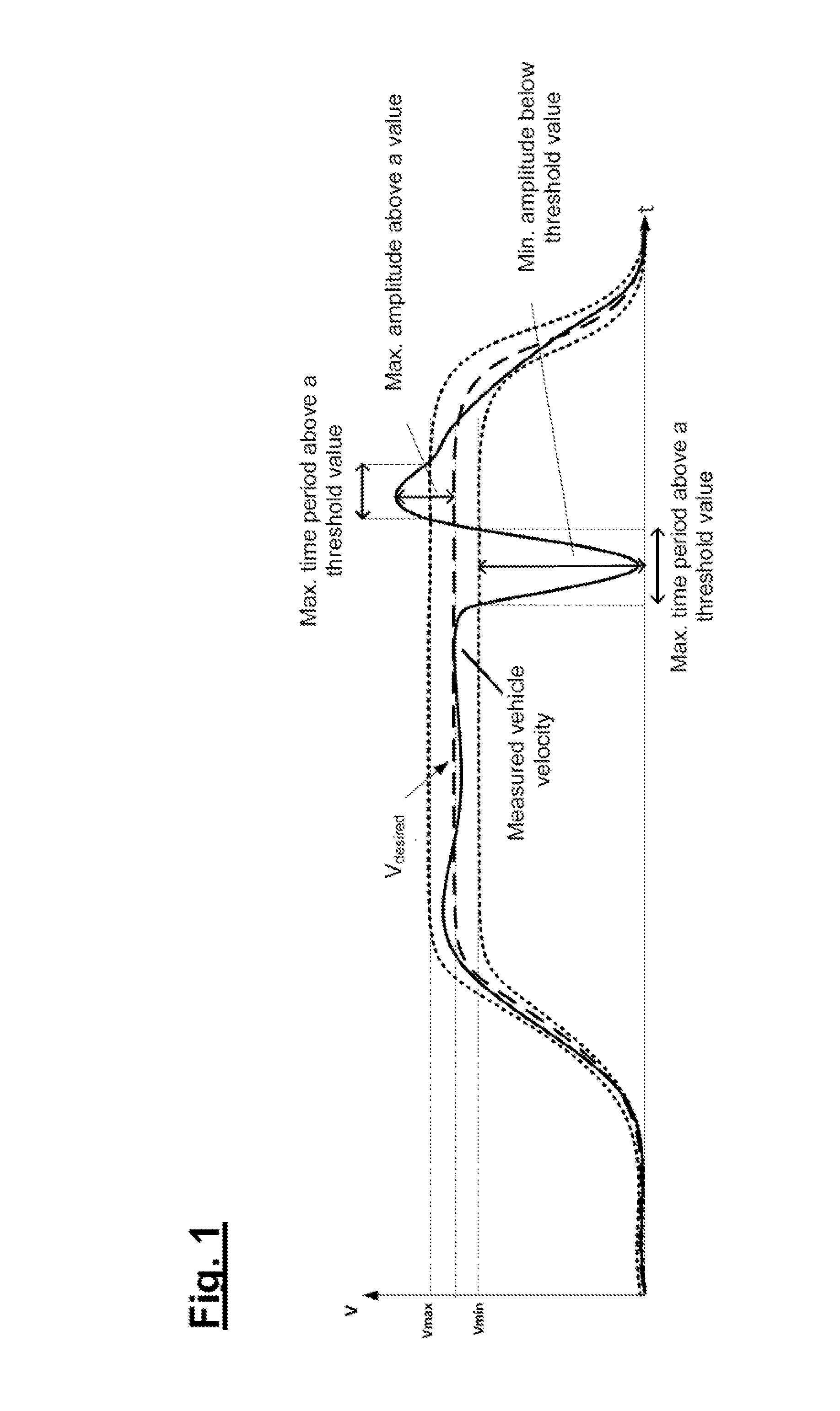
[0005] The longitudinal control procedure is designed or configured so as to maintain the vehicle velocity (V) in a predetermined value range (V.sub.min . . . V.sub.max). It is possible to allow for the vehicle velocity values that lie in this range to be exceeded or for said values not to be achieved in each case for short time periods in order to render it possible for example to perform a maneuver at a curb side, as is illustrated in FIG. 1. However, in the event of these short time periods being exceeded, an appropriate reaction of the system is required.
[0006] DE 10 2009 058 139 A1 discloses inter alia a method and a device for a vehicle control procedure with respect to an object, wherein in order to approach the object more accurately the vehicle is moved up to a first distance from the object at a parking velocity that corresponds to the maximum driving velocity that can be achieved at the idling rotational speed, the vehicle is then maintained at this velocity and, after achieving the distance up to a second distance that corresponds to the stopping distance, said vehicle is braked until it comes to a standstill using a braking device.
[0007] EP 1 327 553 B1 discloses inter alia a parking assistance system and a method for the closed loop control of a parking assistance system, wherein the incline of a road surface is determined and wherein on the basis of the result of this determination the parking assistance is cancelled if the angle of inclination of the road surface is too steep.
[0008] With regard to further prior art, reference is made merely by way of example to U.S. Pat. No. 6,018,692 and EP 2 266 856 B1.
SUMMARY
[0009] It is an object to provide a method and a device for a vehicle control procedure, which renders it possible to reliably detect unexpected situations in which the vehicle control procedure is no longer able to maintain the desired vehicle velocity values, and also to render it possible where necessary to initiate corresponding suitable measures with a small outlay in relation to the apparatus.
[0010] The method for a vehicle control procedure, wherein in the case of this vehicle control procedure a closed loop control of the vehicle velocity is performed on the basis of a predetermined threshold value, comprises the following steps:
determine on the basis of at least one predetermined criterion whether in the case of the closed loop control the vehicle velocity leaves a value range that is defined by at least one velocity threshold value while taking into consideration a tolerance range that defines predetermined, permitted deviations from this value range; and implement a corresponding measure while modifying the vehicle control procedure in dependence upon the result of this determination procedure; wherein the determination procedure is performed on the basis of a signal analysis of least one measurement signal that describes the movement status of the vehicle.
[0011] Certain embodiments in particular the concept of detecting defined operating states merely on the basis of a signal analysis at least of one measurement signal that describes the movement status of the vehicle. This can be performed by way of example with the aid of the deviations between a vehicle velocity desired value and the prevailing vehicle velocity value, the respective time integral of corresponding difference signals, etc.
[0012] In the case of the method, data from external sensors (for example with respect to distance information) is not required for this purpose. As soon as a defined operating status is verified in which the vehicle control procedure is no longer able to maintain the desired vehicle velocity values, the higher-level control procedure can propose or initiate a suitable counter measure (for example interrupt or terminate the respective maneuver, such as for example a parking maneuver, which is being supported by the vehicle control procedure).
[0013] One typical operating status that can be verified is the maneuvering of the vehicle against an unavoidable obstacle that had not been detected for example either by the driver or by the sensors.
[0014] In accordance with one embodiment, the difference between the vehicle velocity and the velocity threshold value is used as the measuring signal that describes the movement status of the vehicle.
[0015] In accordance with one embodiment, a time integral of the difference between the vehicle velocity and the velocity threshold value is used as the measurement signal that describes the movement status of the vehicle.
[0016] In accordance with one embodiment, the predetermined criterion includes the fact that a threshold value is exceeded or not achieved by means of the measurement signal for a predetermined minimum time period.
[0017] In accordance with one embodiment, an engine torque that is exerted in the vehicle is used as the measurement signal that describes the movement status of the vehicle.
[0018] In accordance with one embodiment, the measure that is implemented includes interrupting or terminating a driving maneuver that is supported by means of the vehicle control procedure.
[0019] In accordance with one embodiment, the measure that is implemented includes furthermore transmitting a query to the driver requesting whether the driving maneuver is to be continued or restarted.
[0020] In accordance with one embodiment, the vehicle control procedure includes assisting a parking maneuver.
[0021] In accordance with one embodiment, the measure that is implemented includes braking the vehicle until it comes to a standstill.
[0022] Some embodiments relate to a device for controlling the vehicle, wherein in the case of this vehicle control procedure a closed loop control of the longitudinal velocity of a vehicle is performed on the basis of a predetermined desired value for the vehicle velocity, wherein the device is designed so as to perform a method having the above described features.
BRIEF DESCRIPTION OF THE DRAWINGS
[0023] FIG. 1 illustrates a diagram in which are plotted in an exemplary scenario permissible variations of the vehicle velocity about the desired value for the vehicle velocity; and
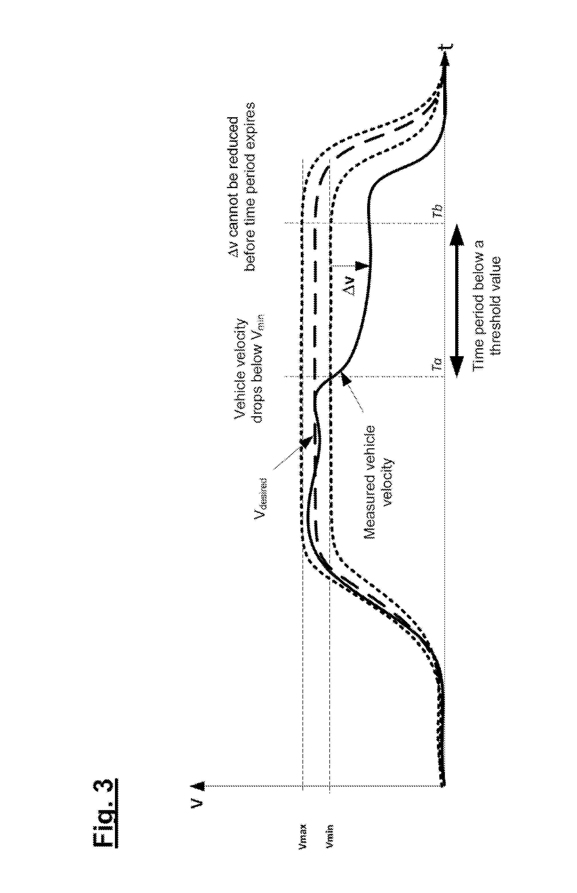
[0024] FIGS. 2-4 illustrate diagrams for explaining different scenarios in which the vehicle velocity leaves a defined value range (V.sub.min . . . V.sub.max) for a time period that is above a defined value.
DETAILED DESCRIPTION
[0025] Furthermore, different scenarios are described with reference to FIGS. 2-4 and table 1, in which the vehicle velocity leaves a defined value range (V.sub.min . . . V.sub.max) for a time period that is above a defined value. Table 1 also illustrates possible reactions of the system and also exemplary maneuvers in which the relevant situation can occur.
[0026] These scenarios have in common that in each case an operating status is detected in which an unexpected situation in which the vehicle control procedure is no longer able to maintain desired vehicle velocity values merely on the basis of a signal analysis at least of one measurement signal that describes the movement status of the vehicle and where necessary a suitable measure is initiated accordingly. This signal analysis can include by way of example the analysis of the deviation between a vehicle velocity desired value and the prevailing vehicle velocity value or the analysis of a time integral of corresponding difference signals.
[0027] In each case, a lower limit value V.sub.min for the vehicle velocity and/or an upper limit value V.sub.max for the vehicle velocity are predetermined to be constant or situation-dependent or also dependent upon the respective vehicle velocity (for example in a reference table as a percentage of the desired value for the vehicle velocity, etc.). The predefined time periods mentioned in each case in Table 1 can be listed in a reference table in dependence upon the prevailing vehicle velocity.
TABLE-US-00001 TABLE 1 Situation Verification Method Possible Reaction Exemplary Maneuver 1 V = 0 km/h and V.sub.desired > The parking The vehicle maneuvers Threshold value for maneuver is against a low-standing defined time period. interrupted and object that has not been V is below V.sub.min and the driver is detected or could not be D = .intg..sub.Ta.sup.Tb(V - V.sub.min)dt requested to check detected by the parking is below a threshold the situation sensors and was difficult value, D is reset each wherein the driver for the driver to detect time if V exceeds the can decide (for example large stone, value V.sub.min. whether to restart low wall, low metal Maximum permissible or terminate the railings etc.). engine torque (during maneuver. parking maneuver) is The parking exerted for a defined maneuver is time period and V = 0 terminated and the km/h. full control of the Integral of the torque vehicle is returned exceeds threshold value. to the driver. 2 0 < V < V.sub.min for The parking The vehicle is heavily defined time period. maneuver is laden and the maneuver is V - V.sub.min is below a interrupted and performed on a steep threshold value for a the driver is asked incline (for example, defined time period. if he still wishes slope, curb stone, uneven V is below V.sub.min to continue with ground etc.). and D = .intg..sub.Ta.sup.Tb(V - V.sub.min)dt the maneuver. is below a threshold The parking value, D is reset each maneuver is time if V exceeds the terminated (i.e. Value V.sub.min. the vehicle is Maximum permissible braked until it engine torque (during comes to a the parking maneuver) standstill) and the is exerted for a defined full control of the time period. vehicle is returned Integral of the torque to the driver. exceeds threshold value. No special reaction of the system, the maneuver is continued since the vehicle is still capable of moving. 3 V > V.sub.max for a defined The parking The vehicle is heavily time period. maneuver is laden and the maneuver is V is above V.sub.max and terminated (i.e. performed driving down a D = .intg..sub.Ta.sup.Tb(V - V.sub.max)dt the vehicle is hill with a steep gradient is below a threshold braked until it (for example a sloping value, D is reset each comes to a road, curb stone, holes in time if V is below the standstill) and the the road etc.). value V.sub.max. full control of the V - V.sub.max is above the vehicle is returned threshold value for a to the driver. defined time period. Integral of the torque exceeds threshold value and V > V.sub.max.
* * * * *
D00001
D00002
D00003
D00004
XML
uspto.report is an independent third-party trademark research tool that is not affiliated, endorsed, or sponsored by the United States Patent and Trademark Office (USPTO) or any other governmental organization. The information provided by uspto.report is based on publicly available data at the time of writing and is intended for informational purposes only.
While we strive to provide accurate and up-to-date information, we do not guarantee the accuracy, completeness, reliability, or suitability of the information displayed on this site. The use of this site is at your own risk. Any reliance you place on such information is therefore strictly at your own risk.
All official trademark data, including owner information, should be verified by visiting the official USPTO website at www.uspto.gov. This site is not intended to replace professional legal advice and should not be used as a substitute for consulting with a legal professional who is knowledgeable about trademark law.