Polishing Apparatus And Substrate Processing Apparatus
SONE; Tadakazu ; et al.
U.S. patent application number 16/366546 was filed with the patent office on 2019-10-03 for polishing apparatus and substrate processing apparatus. The applicant listed for this patent is EBARA CORPORATION. Invention is credited to Hideo AIZAWA, Hiroshi AONO, Ryuichi KOSUGE, Kenji SHINKAI, Tadakazu SONE.
| Application Number | 20190299360 16/366546 |
| Document ID | / |
| Family ID | 68057572 |
| Filed Date | 2019-10-03 |


| United States Patent Application | 20190299360 |
| Kind Code | A1 |
| SONE; Tadakazu ; et al. | October 3, 2019 |
POLISHING APPARATUS AND SUBSTRATE PROCESSING APPARATUS
Abstract
A polishing apparatus includes a polishing table supplied with liquid on a upper surface and rotating around a central axis, a liquid receiver having an annular shape and disposed below a peripheral portion of the polishing table, and a drain member having a tubular shape, attached to a peripheral portion of the polishing table, and including a lower end portion extending toward the liquid receiver.
| Inventors: | SONE; Tadakazu; (Tokyo, JP) ; KOSUGE; Ryuichi; (Tokyo, JP) ; SHINKAI; Kenji; (Tokyo, JP) ; AONO; Hiroshi; (Tokyo, JP) ; AIZAWA; Hideo; (Tokyo, JP) | ||||||||||
| Applicant: |
|
||||||||||
|---|---|---|---|---|---|---|---|---|---|---|---|
| Family ID: | 68057572 | ||||||||||
| Appl. No.: | 16/366546 | ||||||||||
| Filed: | March 27, 2019 |
| Current U.S. Class: | 1/1 |
| Current CPC Class: | B24B 55/03 20130101; B24B 37/013 20130101; B24B 57/00 20130101; B24B 37/16 20130101; B24B 37/22 20130101; B24B 37/24 20130101; B24B 37/10 20130101; B24B 53/017 20130101; B24B 37/015 20130101; B24B 57/02 20130101 |
| International Class: | B24B 57/00 20060101 B24B057/00; B24B 37/24 20060101 B24B037/24; B24B 37/22 20060101 B24B037/22 |
Foreign Application Data
| Date | Code | Application Number |
|---|---|---|
| Apr 2, 2018 | JP | 2018-070919 |
| Apr 18, 2018 | JP | 2018-080025 |
Claims
1. A polishing apparatus comprising: a polishing table supplied with liquid on an upper surface and rotating around a central axis; a liquid receiver having an annular shape and disposed below a peripheral portion of the polishing table; and a drain member having a tubular shape, attached to a peripheral portion of the polishing table, and comprising a lower end portion extending toward the liquid receiver.
2. The polishing apparatus according to claim 1, wherein: the liquid receiver comprises an inner peripheral wall disposed radially inward of the lower end portion of the water drain member; and the lower end portion of the drain member extends downward from an upper end portion of the inner peripheral wall.
3. The polishing apparatus according to claim 1, wherein: a step to which the water drain member is attached is formed in the peripheral edge portion of the polishing table; the water drain member is attached to a bottom surface of the step via a bolt; a first seal member sealing a gap between the water drain member and a side surface of the stepped portion in the radial direction is provided; and a second seal member sealing an insertion hole of the water drain member through which the bolt is inserted is provided.
4. The polishing apparatus according to claim 1, further comprising: a cover member disposed radially outward of the water drain member and having a gradually decreasing gap in the radial direction with respect to the water drain member toward the upper surface of the polishing table; and a gas-liquid separation device sucking gas via the liquid receiver and separating liquid included in the gas, wherein a suction path of the gas-liquid separation device is a gap formed between the water drain member and the cover member.
5. The polishing apparatus according to claim 4, wherein: the cover member is disposed with a clearance from an outer peripheral wall of the liquid receiver; and a gap dimension between the cover member and the outer peripheral wall is smaller than a gap dimension between the cover member and an upper end portion of the water drain member.
6. The polishing apparatus according to claim 4, wherein the cover is vertically movable.
7. A polishing apparatus comprising a polishing table in which a substrate is pressed against an upper surface of the polishing table and which rotates around a central axis, wherein the polishing table comprises: a table forming the upper surface and comprising a heat medium flow path in an internal portion; and a table base detachably supporting the table.
8. The polishing apparatus according to claim 7, further comprising: a plurality of bolts detachably fixing a first peripheral portion of the table to a second peripheral portion of the table base; and in the radially inward of the plurality of bolts, one or more knock pins positioning the table with respect to the table base.
9. The polishing apparatus according to claim 8, comprising a drain member having a tubular shape and covering the table and a dividing surface of the table base from outside in the radial direction, wherein the water drain member is detachably attached to a peripheral portion of the polishing table by the plurality of bolts.
10. The polishing apparatus according to claim 7, wherein: a flange having a tubular shape and rotatably driven by a motor is connected to a lower surface side of the table base; and the flange forms a space for attaching a film thickness measurement device on the lower surface side of the table base that measures a film thickness of the substrate.
11. The polishing apparatus according to claim 7, wherein on a lower surface side of a peripheral portion of the table base, a drain protrusion having an annular shape protruding downward is formed.
12. The polishing apparatus according to claim 8, wherein a coating layer to which a polishing pad is peelably adhered is formed on an upper surface of the table.
13. The polishing apparatus according to claim 12, wherein the coating layer is a fluororesin coating layer.
14. The polishing apparatus according to claim 12, wherein the coating layer is a glass coating layer.
15. The polishing apparatus according to claim 12, wherein the coating layer is a ceramic coating layer.
16. The polishing apparatus according to claim 12, wherein the coating layer is a diamond coating layer.
17. A substrate processing apparatus comprising: a polishing portion polishing a substrate; and a cleaning portion cleaning the substrate polished by the polishing portion, wherein the polishing portion comprises the polishing apparatus according to claim 1.
Description
CROSS REFERENCE TO RELATED APPLICATION
[0001] The present application claims priority based on Japanese Patent Application No. 2018-070919 filed on Apr. 2, 2018 and Japanese Patent Application No. 2018-080025 filed Apr. 18, 2018, and the contents of which are incorporated herein by reference.
BACKGROUND OF THE INVENTION
Field of the Invention
[0002] The present invention relates to a polishing apparatus and a substrate processing apparatus.
Background Art
[0003] Conventionally, as one of substrate processing apparatuses for processing a substrate such as a silicon wafer, Chemical Mechanical Polishing (CMP) apparatus is known. This substrate processing apparatus includes a polishing portion (polishing apparatus) for polishing a substrate and a cleaning portion for cleaning the substrate. As disclosed in Japanese Unexamined Patent Application, First Publication No. 2017-18930, the polishing apparatus includes a polishing table and a polishing head also called a top ring. A polishing pad is attached to the rotating upper surface of the polishing table.
[0004] In such a polishing apparatus, a polishing liquid (liquid) including abrasive grains such as silica (SiO.sub.2) and ceria (CeO.sub.2) is supplied from a polishing liquid nozzle onto a rotation polishing table affixed with a polishing pad. In addition, the substrate held on the lower surface of the polishing head is pressed while rotating on the polishing table (polishing pad). Due to this pressing, the substrate surface abutting against the polishing pad surface is formed on a desired flat surface by both rotations of the polishing table and the polishing head in the presence of the polishing liquid.
[0005] The substrate formed on the desired flat surface is transferred to the cleaning portion and subjected to cleaning processing. A gas mixture including an inert gas such as nitrogen gas is supplied from the atomizer nozzle onto the upper surface of the polishing pad after the substrate has been transferred. As a result, the polishing pad surface is cleaned and used for polishing the next substrate.
[0006] In the polishing process described above, there are polishing liquid supplied from the polishing liquid nozzle, gas mixture supplied from the atomizer nozzle, and polishing waste generated by polishing on the polishing table. In order to process the liquid including the polishing waste, the polishing apparatus is provided with a drainage and exhaust structure.
[0007] The drainage and exhaust structure provided in the polishing apparatus of Japanese Unexamined Patent Application, First Publication No. 2017-18930 includes a polishing liquid reception pan (liquid receiver) and a gas-liquid separator. The polishing liquid reception pan is provided near the outer periphery of the polishing table and is configured to be able to receive the dropping liquid due to the rotation of the polishing table. In addition, the gas-liquid separator is configured to introduce the liquid received in the polishing liquid reception pan and to separate the gas and liquid during the dropping of the introduced liquid.
[0008] In addition, in the polishing process described above, the temperature of the polishing table rises due to generation of frictional heat due to polishing. Therefore, in the polishing table, as shown in Japanese Unexamined Patent Application, First Publication No. 2007-222965, a heat medium flow path for passing a heat medium such as water adjusting the temperature is formed.
[0009] A heat medium is supplied to one end side of the heat medium flow path via the shaft portion of the polishing table, and the supplied heat medium flows toward the other end side of the heat medium flow path. Therefore, the polishing table can be cooled or heated while the heat medium flows through the heat medium flow path. The heat medium having undergone such temperature adjustment is discharged from the other end side of the heat medium flow path and taken out to the outside via the shaft portion.
[0010] As shown in, for example, Japanese Unexamined Patent Application, First Publication No. 2016-16491, the heat medium is taken in and out from the polishing table by using a pipe provided in the rotation shaft of the polishing table and provided with a rotary joint at the lower portion. That is, a heat-medium supply pipe and a heat medium return pipe are attached to the pipe, and the heat medium is configured to be taken in or out through the rotary joint to the heat-medium supply pipe and the heat medium return pipe. The pipe is also used for power supply of a sensor provided at the lower portion of the polishing table and for piping of leads of signals.
[0011] However, in the conventional drainage and exhaust structure, a polishing liquid reception pan is provided near the outer periphery of the polishing table so that the polishing liquid reception pan can simply accept liquid including polishing waste which moves and drops due to rotation of the polishing table. For this reason, it has been desired to be able to more actively discharge the liquid from the polishing table to the polishing liquid reception pan. If the liquid can be more actively discharged from the polishing table, the mist and the like existing around the polishing table can be promptly discharged, and the cleanness around the polishing table can be improved.
[0012] In addition, the optimum temperature of the upper surface of the polishing table varies depending on the type of the substrate and the polishing rate, and there are cases where it is desired to change the heat medium flow path in the polishing table or the polishing table itself according to specifications thereof. In the conventional polishing table, from the upper surface side where the heat medium flow path is formed to the lower surface side connected to the motor, they are integrated, and it is necessary to replace the entire polishing table. For this reason, there is a disadvantage in that the manufacturing cost increases.
SUMMARY
[0013] The present invention has been made in view of the above circumstances, and provides a polishing apparatus capable of actively discharging liquid existing on a polishing table, and a substrate processing apparatus including such a polishing apparatus.
[0014] The present invention has been made further in view of the above circumstances, and provides a polishing apparatus capable of changing the specification of a polishing table at a low cost based on the purpose of temperature control, and a substrate processing apparatus including such polishing apparatus.
[0015] (1) A polishing apparatus according to one aspect of the present invention includes a polishing table supplied with liquid on an upper surface and rotating around a central axis, a liquid receiver having an annular shape and disposed below a peripheral portion of the polishing table, and a drain member having a tubular shape, attached to a peripheral portion of the polishing table, and including a lower end portion extending toward the liquid receiver.
[0016] (2) In the polishing apparatus described in the above aspect (1), it is preferable that the liquid receiver includes an inner peripheral wall disposed radially inward of the lower end portion of the water drain member, and the lower end portion of the drain member extends downward from an upper end portion of the inner peripheral wall.
[0017] (3) In the polishing apparatus described in the above aspect (1) or (2), it is preferable that a step to which the water drain member is attached is formed in the peripheral edge portion of the polishing table, the water drain member is attached to a bottom surface of the step via a bolt, a first seal member sealing a gap between the water drain member and a side surface of the stepped portion in the radial direction is provided, and a second seal member sealing an insertion hole of the water drain member through which the bolt is inserted is provided.
[0018] (4) In the polishing apparatus described in any one of the above aspects (1) to (3), it is preferable that the polishing apparatus further includes a cover member disposed radially outward of the water drain member and having a gradually decreasing gap in the radial direction with respect to the water drain member toward the upper surface of the polishing table, and a gas-liquid separation device sucking gas via the liquid receiver and separating liquid included in the gas. A suction path of the gas-liquid separation device is a gap formed between the water drain member and the cover member.
[0019] (5) In the polishing apparatus described in the above aspect (4), it is preferable that the cover member is disposed with a clearance from an outer peripheral wall of the liquid receiver, and a gap dimension between the cover member and the outer peripheral wall is smaller than a gap dimension between the cover member and an upper end portion of the water drain member.
[0020] (6) In the polishing apparatus described in the above aspect (4) or (5), it is preferable that the cover is vertically movable.
[0021] (7) A polishing apparatus according to one aspect of the present invention includes a polishing table in which a substrate is pressed against an upper surface of the polishing table and which rotates around a central axis. The polishing table includes a table forming the upper surface and including a heat medium flow path in an internal portion, and a table base detachably supporting the table.
[0022] (8) In the polishing apparatus described in the above aspect (7), it is preferable that the polishing apparatus further includes a plurality of bolts detachably fixing a first peripheral portion of the table to a second peripheral portion of the table base, and in the radially inward of the plurality of bolts, one or more knock pins positioning the table with respect to the table base.
[0023] (9) In the polishing apparatus described in the above aspect (8), it is preferable that the polishing apparatus includes a drain member having a tubular shape and covering the table and a dividing surface of the table base from outside in the radial direction, and the water drain member is detachably attached to a peripheral portion of the polishing table by the plurality of bolts.
[0024] (10) In the polishing apparatus described in any one of the above aspects (7) to (9), it is preferable that a flange having a tubular shape and rotatably driven by a motor is connected to a lower surface side of the table base, and the flange forms a space for attaching a film thickness measurement device on the lower surface side of the table base that measures a film thickness of the substrate.
[0025] (11) In the polishing apparatus described in any one of the above aspects (7) to (10), it is preferable that on a lower surface side of a peripheral portion of the table base, a drain protrusion having an annular shape protruding downward is formed.
[0026] (12) In the polishing apparatus described in any one of the above aspects (7) to (11), it is preferable that a coating layer to which a polishing pad is peelably adhered is formed on an upper surface of the table.
[0027] (13) In the polishing apparatus described in the above aspect (12), it is preferable that the coating layer is a fluororesin coating layer.
[0028] (14) In the polishing apparatus described in the above aspect (12), it is preferable that the coating layer is a glass coating layer.
[0029] (15) In the polishing apparatus described in the above aspect (12), it is preferable that the coating layer is a ceramic coating layer.
[0030] (16) In the polishing apparatus described in the above aspect (12), the coating layer is a diamond coating layer.
[0031] (17) A substrate processing apparatus according to one aspect of the present invention includes a polishing portion polishing a substrate, and a cleaning portion cleaning the substrate polished by the polishing portion. The polishing portion includes the polishing apparatus described in any one of the above aspects (1) to (16).
[0032] According to the aspect of the present invention described above, since the cylindrical water drain member in which the lower end portion extends toward the liquid receiver is provided at the peripheral edge portion of the polishing table, it is possible to efficiently guide the liquid from the upper surface of the polishing table to the liquid receiver, and the cleanness around the polishing table can be improved.
[0033] Furthermore, according to the aspects of the present invention, since the table having the heat medium flow path is detachably supported on the table base, only the portion of the table having the heat medium flow path is replaced based on the purpose of temperature control, and the specification of the polishing table can be changed at low cost.
BRIEF DESCRIPTION OF THE DRAWINGS
[0034] FIG. 1 is a configuration diagram of a polishing table and a peripheral structure thereof included in a polishing apparatus according to the first embodiment of the present invention.
[0035] FIG. 2 is an enlarged view of a portion A in FIG. 1.
[0036] FIG. 3 is a perspective view of a polishing liquid receiver provided in a polishing apparatus according to the first embodiment of the present invention.
[0037] FIG. 4 is a cross-sectional view of a gas-liquid separator included in the polishing apparatus according to the first embodiment of the present invention.
[0038] FIG. 5 is a plan view showing the overall configuration of a substrate processing apparatus according to a first embodiment of the present invention.
[0039] FIG. 6 is a configuration diagram of a polishing table and a peripheral structure thereof included in a polishing apparatus according to the second embodiment of the present invention.
[0040] FIG. 7 is a plan view of a polishing table according to the second embodiment of the present invention.
[0041] FIG. 8 is an explanatory view showing an internal structure of a shaft according to the second embodiment of the present invention.
[0042] FIG. 9 is a schematic perspective view showing an entire structure of a polishing unit shown in FIG. 5.
[0043] FIG. 10 is a cross-sectional view showing the attachment structure of a polishing pad according to the second embodiment of the present invention.
DESCRIPTION OF THE PREFERRED EMBODIMENTS
[0044] Hereinafter, a polishing apparatus and a substrate processing apparatus according to an embodiment of the present invention will be described with reference to the drawings. In order to better understand the gist of the invention, the following embodiments are described by way of examples and do not limit the present invention unless otherwise specified. Further, in the drawings used in the following description, in order to make the features of the present invention easy to understand, there are cases where the main portion is enlarged for the sake of convenience, and the dimensional ratio of each component is not necessarily the same as the actual dimension. Further, for the sake of easy understanding of the features of the present invention, there are omitted portions for convenience.
First Embodiment
(Polishing Apparatus)
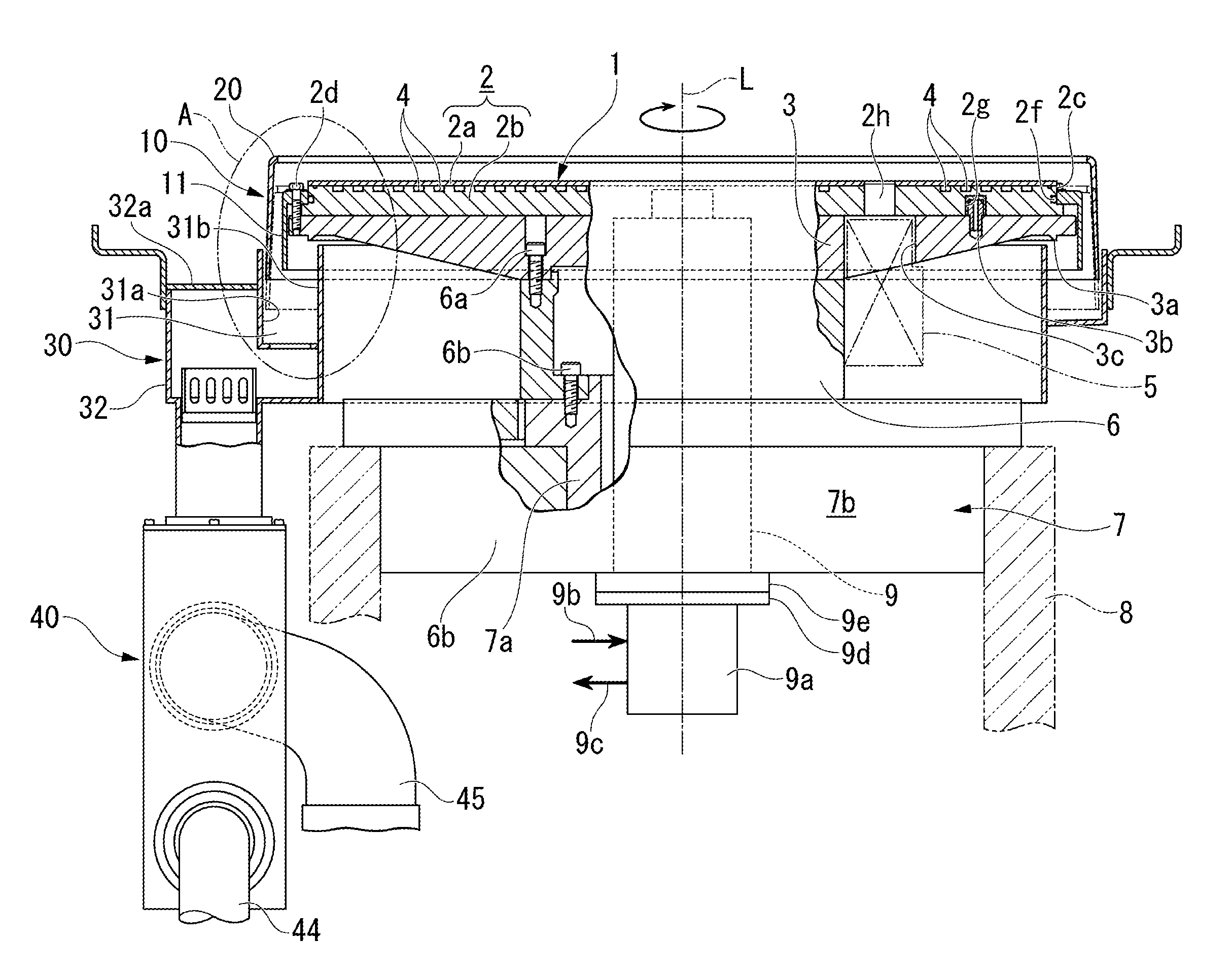
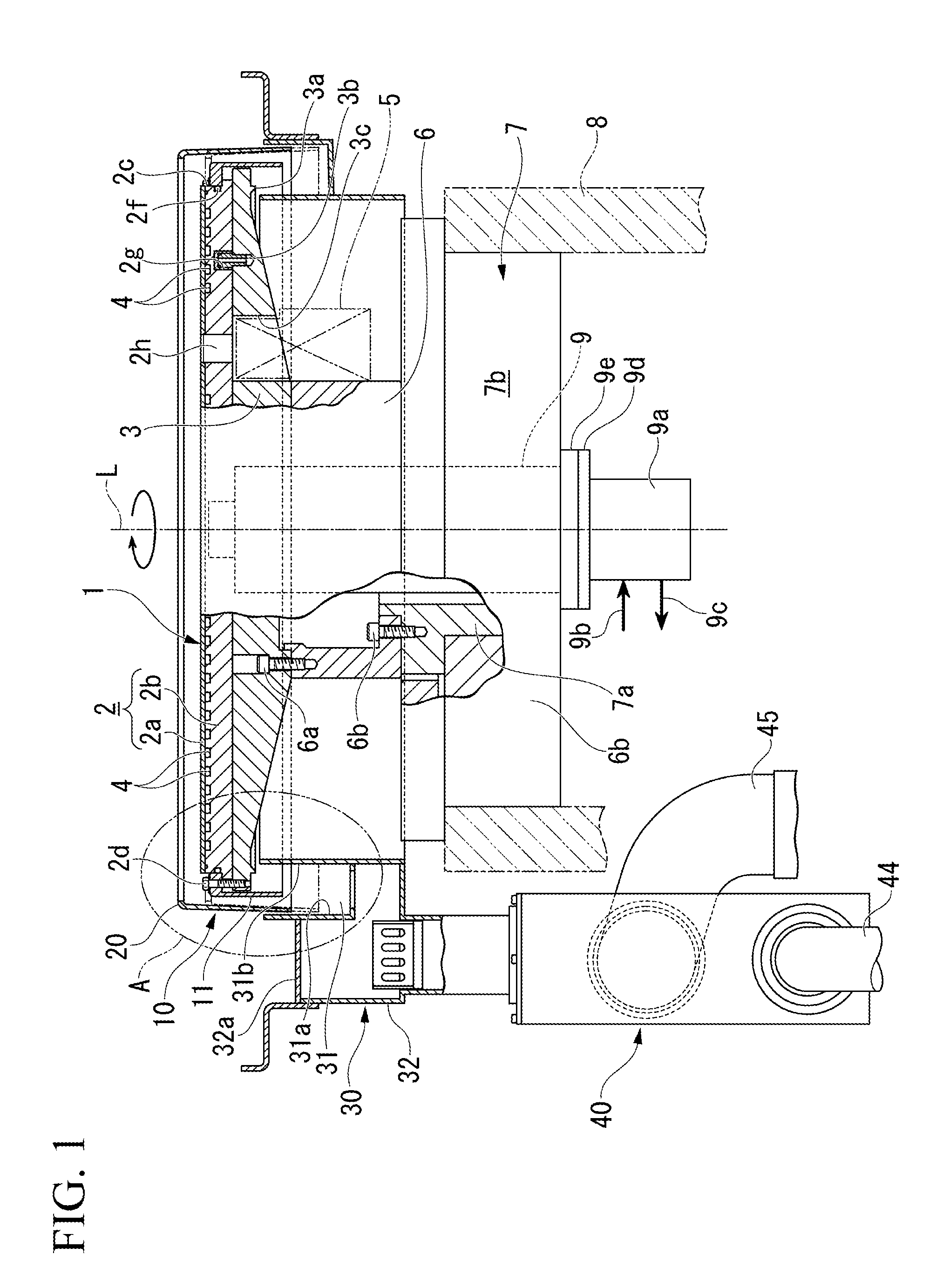
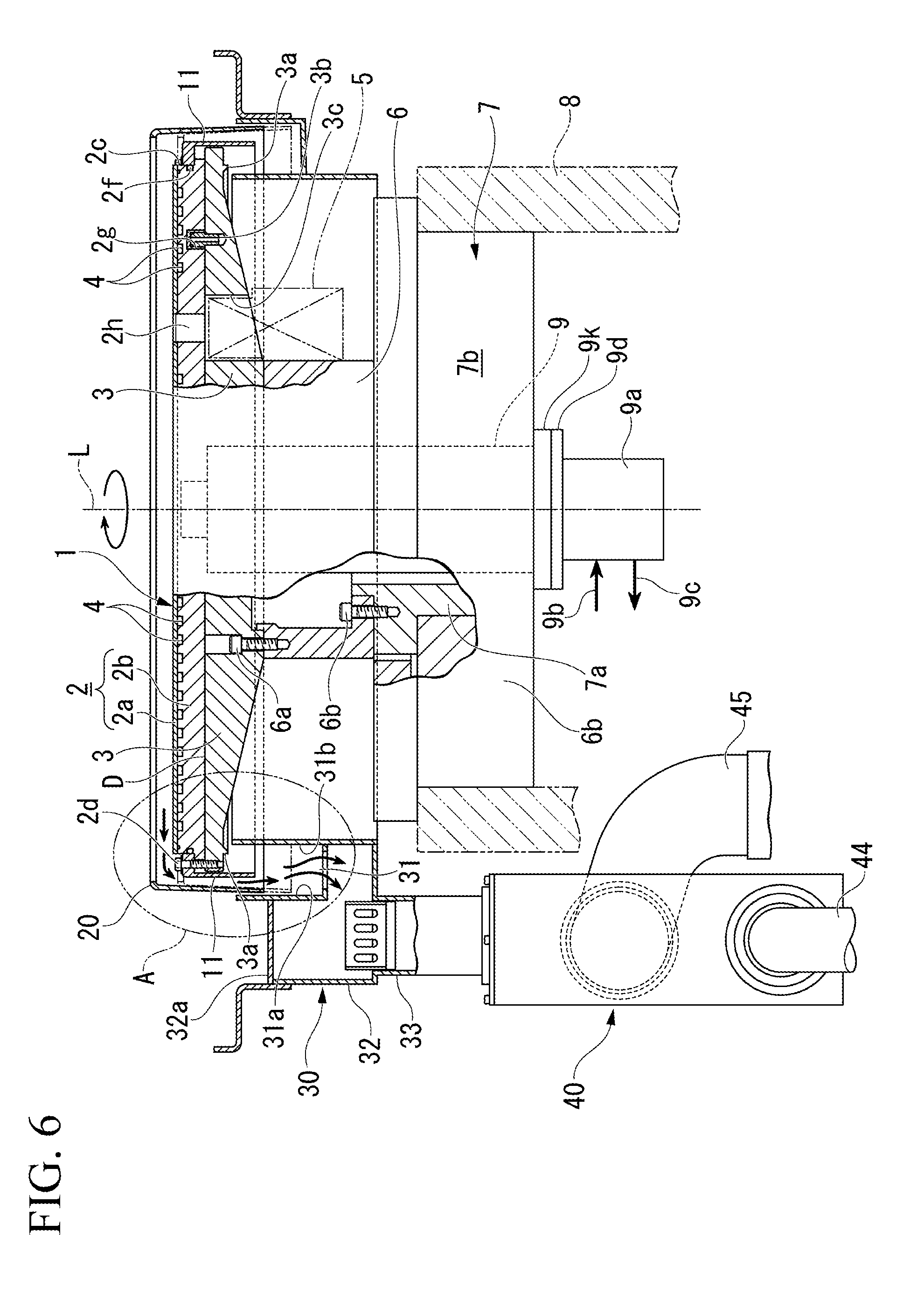
[0045] FIG. 1 is a configuration diagram of a polishing table 1 included in a polishing apparatus according to one embodiment and its peripheral structure. FIG. 2 is an enlarged view of a portion A of FIG. 1.
[0046] This polishing apparatus is incorporated in a portion of a substrate processing apparatus (described later) for processing a semiconductor substrate such as a silicon wafer. The polishing apparatus is configured to include a polishing table 1 and a top ring; however, here only the polishing table 1 is shown.
[0047] In the following description, before describing the substrate processing apparatus, the polishing table 1 of the polishing apparatus and its peripheral structure (drainage and exhaust structure 10) which is a main portion of the present invention will be described.
[0048] In the polishing table 1 shown in FIG. 1, the planar shape of the upper surface is formed in a circular shape and rotates around a central axis L passing through the center of the circular shape. This polishing table 1 has a table 2 positioned on the upper surface side and a table base 3 on which the table 2 is stacked. A polishing pad is attached to the upper surface of the table 2; however, it is omitted here. An opening corresponding to the sensor hole 2h provided in a table 2 described later is formed in the polishing pad.
[0049] The material of the table 2 is selected from a viewpoint of heat conductivity, ease of processing, and the like, and is made of stainless steel, ceramics, or aluminum alloy, for example. The table 2 is formed by vertically joining a first table portion 2a located on the upper side and a second table portion 2b located on the lower side of the first table portion 2a.
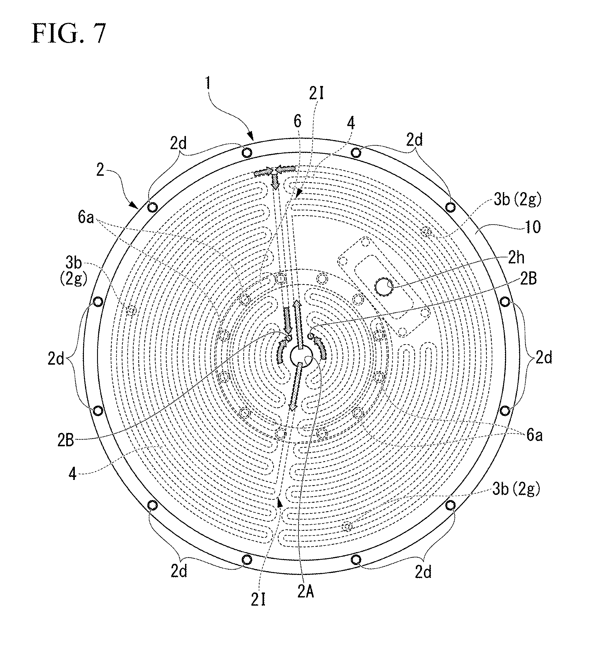
[0050] In the second table portion 2b, a heat medium flow path 4 is formed. The heat medium flow path 4 is a recess groove formed on the upper surface of the second table portion 2b so as to substantially cover the entire upper surface thereof. The first table portion 2a is a plate member (lid member) joined to the upper surface of the second table portion 2b and closing the upper surface opening of the recess groove of the heat medium flow path 4. A heat medium (temperature-controlled water or the like) is supplied to the heat medium flow path 4 from the rotary joint 9a side to be described later via the shaft 9.
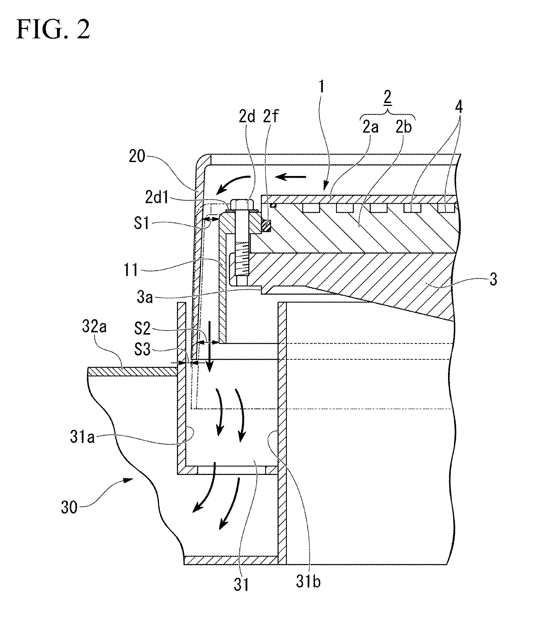
[0051] On the upper surface side of the peripheral portion of the table 2, a step 2c is provided. The depth of the step 2c is determined such that a sum of the thickness of the flinger (water drain member) 11 and the head height of the bolt 2d for attaching the flinger 11 and the table 2 to the table base 3 is below an upper surface position of the first table portion 2a. In the present embodiment, the flinger 11 is one of the constituent members of the drainage and exhaust structure 10.
[0052] As shown in FIG. 2, a seal washer 2d1 (second seal member) is sandwiched between the head portion of the bolt 2d and the flinger 11. The seal washer 2d1 prevents the liquid on the table 2 from entering the table base 3 side through the insertion hole of the flinger 11 through which the bolt 2d is inserted.
[0053] On the side surface of the step 2c provided on the table 2, a recess groove recessed radially inward is provided, and an O ring 2f (first seal member) is disposed in the recess groove. The 0 ring 2f abuts against the inner end face of the flinger 11 attached to the step 2c. The 0 ring 2f seals a gap in the radial direction between the flinger 11 and the side face of the step 2c and prevents the liquid on the table 2 from entering the table base 3 side through the gap.
[0054] Returning to FIG. 1, on the lower surface of the table 2, one or a plurality of knock pin holes 2g is provided with a predetermined interval therebetween on the same radius. In FIG. 1, only one knock pin hole 2g is shown out of a plurality (for example, three) of knock pin holes 2g. The installation position of the knock pin hole 2g corresponds to the installation position of the knock pin 3b provided on the table base 3 described later. In the table 2, a sensor hole 2h penetrating in the vertical direction is provided at a position radially away from the central axis L.
[0055] The table base 3 can be made of a material having sufficient rigidity, for example, made of the aforementioned SUS 304 or ceramics. If made of ceramic, it may become expensive. In addition, it can also be made of, for example, an aluminum alloy from the viewpoint of density, ease of processing, and the like. For example, the aforementioned aluminum alloy for forging of A6061P or aluminum alloy casting with AC4CH is suitable.
[0056] The upper surface of the table base 3, that is, the surface in contact with the bottom surface (lower surface) of the table 2 is formed in a circular shape similar to that of the table 2. When viewed from the front side of the table base 3, it is formed in an inverted trapezoidal shape. An annular drain protrusion 3a protruding downward is integrally formed on the bottom surface side of the peripheral portion of the table base 3 and radially inward of the fastening position of the bolt 2d.
[0057] On the upper surface of the table base 3, as shown in FIG. 2, a plurality of knock pins 3b are implanted so as to protrude toward the table 2 with one or the same radius kept at a predetermined interval from each other on the radially inner side than the bolt 2d. In FIG. 1, only one knock pin 3b among a plurality (for example, three) of knock pins 3b is shown. The knock pins 3b are provided so as to face the knock pin holes 2g provided in the above-described table 2. The table 2 and the table base 3 are positioned by inserting the knock pin 3b into the knock pin hole 2g and are fastened together with the flinger 11 by bolts 2d so as to be rotatable integrally around the central axis L.
[0058] Further, the table base 3 is provided with a sensor mounting portion 3c. In the sensor mounting portion 3c, when the knock pins 3b of the table base 3 are inserted into the knock pin holes 2g of the table 2 and both are positioned and laminated, the sensor mounting portion 3c is positioned at a position facing the sensor hole 2h provided in the table 2. To the sensor attachment portion 3c, the wafer thickness detector (thickness measurement device) 5 is mounted to detect the flat surface state of the substrate (not shown) to be polished with the polishing table 1. The wafer film thickness detector 5 is in watertight contact with the sensor hole 2h.
[0059] A flange 6 is connected to the central portion of the bottom surface of the table base 3. The flange 6 is made of a cylindrical body, and its upper end portion is fixed to the table base 3 by using bolts 6a. The length in the axial direction of the flange 6 is determined to a length that extends to below the lower end position of the wafer thickness detector 5 attached to the table base 3. Therefore, the flange 6 also has a role to secure a space to mount the wafer thickness detector 5 in the table base 3.
[0060] A motor 7 is connected to the lower end portion of the flange 6. The motor 7 has a hollow motor rotation shaft 7a, and the upper end portion of the motor rotation shaft 7a is fixed by using the lower end portion of the flange 6 and the bolt 6b. The motor casing 7b of the motor 7 is fixed to a frame 8 on the stationary side of the polishing apparatus. That is, the polishing table 1 is supported by the frame 8 via the motor 7 and the flange 6. Then, when the motor 7 is driven to rotate, the polishing table 1 can rotate the table 2 around the central axis L through, the motor 7, the flange 6, the table base 3, and the bolt 2d fixing the knock pins 3b and flinger 11.
[0061] The upper end portion of the shaft 9 passing through the hollow motor rotation shaft 7a of the motor 7 is connected to the center of the bottom surface portion of the polishing table 1. The lower end portion of the shaft 9 is connected to the rotary joint rotation axis 9d of the rotary joint 9a via a cooling water flange 9e fixed to the lower end portion of the motor rotation shaft 7a. Therefore, the shaft 9 above the rotary joint 9a can rotate with the table 2.
[0062] The rotary joint 9a is connected to a heat-medium supply pipe 9b for supplying a heat medium to the shaft 9 side and a heat medium return pipe 9c for returning the heat medium discharged from the shaft 9 side. Although not shown in the drawing, a pipe line for supplying the heat medium supplied to the shaft 9 to one end of the heat medium flow path 4 in the table 2 and a pipe line for returning the heat medium discharged from the other end of the heat medium flow path 4 to the side of the rotary joint 9a are formed inside the shaft 9.
[0063] Therefore, when a heat medium is supplied to the heat-medium supply pipe 9b of the rotary joint 9a, the supplied heat medium passes through the heat medium flow path 4 in the table 2 and again returns to the heat-medium returning pipe 9c of the rotary joint 9a. In this manner, by supplying the heat medium via the rotary joint 9a, the upper surface of the table 2 can be adjusted to a desired temperature even if the table 2 is rotating.
[0064] Next, the drainage and exhaust structure 10 will be described with reference to FIGS. 3 and 4.
[0065] As shown in FIG. 2, the drainage and exhaust structure 10 includes a flinger 11 (water drain member), a cover 20 (cover member), a polishing liquid receiver 30 (liquid receiver), a gas-liquid separating device 40 (see FIG. 1).
[0066] As described above, the flinger 11 shown in FIG. 1 is provided in the step 2c of the table 2, and its overall shape is formed into a cylindrical shape that can cover the entire side surface of the table 2. The vertical cross-sectional shape of the flinger 11 is such that the L-shaped top and bottom are reversed, and the upper bent portion of that form is attached to the step 2c of the table 2. The length of the portion vertically descending from the bent portion is determined so as to extend downwardly from the lower end position of the water drain protrusion 3a provided on the table base 3.
[0067] Next, the cover 20, the polishing liquid receiver 30, and the gas-liquid separator 40 associated with the polishing table 1 having the above structure will be described. The cover 20 is provided on the fixed frame side of a polishing apparatus (not shown), and its overall shape is formed in a cylindrical shape that can cover the entire side surface of the flinger 11 at a position radially outward of the flinger 11. The cover 20 is formed so that the gap in the radial direction with the flinger 11 gradually decreases toward the upper surface of the polishing table 1. More specifically, when the gap dimension on the upper surface of the polishing table 1 is S1, and the gap dimension at the lower end portion of the flinger 11 is S2, then the relation S1<S2 is established.
[0068] That is, the cover 20 is positioned at a predetermined distance radially outward from the flinger 11, and its inner peripheral side is inclined (reduced in diameter) slightly toward the center of the tubular shape. Further, the axial length of the cylindrical cover 20 is sufficiently longer than the length of the portion vertically lowered from the bent portion of the flinger 11. Therefore, the gap formed between the flinger 11 and the cover 20 forms a kind of orifice structure being narrowed toward upward.
[0069] The cover 20 is movable in the vertical direction (axial direction) as indicated by the two-dot chain line. The vertical movement is performed by an actuator provided on the fixed frame side of a polishing apparatus (not shown); however, it can also be done manually. The solid line in FIG. 2 shows a state in which the cover 20 has moved upward, and is in a state capable of receiving the polishing liquid and the gas mixture discharged from the upper surface side of the table 2. On the other hand, the two-dot chain line in FIG. 2 shows a state in which the cover 20 has moved downward. The downward movement of the cover 20 is carried out when replacing the polishing pad affixed to the table 2 or during a maintenance work of the polishing head which is also referred to a top ring and the table 2.
[0070] The polishing liquid receiver 30 is provided on the fixed frame side of a polishing apparatus (not shown), and the upper portion has a gutter 31 (see FIG. 3) having an annular opening. As shown in FIG. 2, the outer circumferential wall 31a on the radially outside of the gutter 31 is arranged radially outward of the lower end portion of the cover 20. Even when the cover 20 moves upward or downward, the outer circumferential wall 31a and the lower end of the cover 20 can be overlapped. If the gap dimension between the cover 20 and the outer peripheral wall 31a when the cover 20 is moved upward is S3, then the relation S3<S1<S2 is established. S3 may be made sufficiently small. As a result, inflow of outside air into the inside of the gutter 31 is reduced, and the suction efficiency of the gas-liquid separator 40 described later is improved.
[0071] In addition, when an exhaust processing device (suction device) (not shown) connected to an exhaust pipe 45, which will be described later, is included, air on the motor side is taken in when S3 is small, rather than outside air is taken in. As a result, the polishing liquid flows down almost directly downward as shown by the arrows, so that the polishing liquid hardly flows around to the motor side, and the polishing liquid does not easily enter the gap of the portion where the members are fastened.
[0072] On the other hand, the inner circumferential wall 31b on the inner side in the radial direction of the gutter 31 is disposed radially inward of the lower end portion of the flinger 11. The lower end portion of the flinger 11 extends below the upper end portion of the inner peripheral wall 31b, and both overlap. Therefore, a kind of labyrinth structure can be formed by the flinger 11 and the inner circumferential wall 31b of the polishing liquid receiver 30. As a result, it is possible to prevent the gas liquid from flowing inward in the radial direction from the inner peripheral wall 31b of the polishing liquid receiver 30, that is, the bottom surface side of the table base 3.
[0073] As shown in FIG. 3, a drainage chamber 32 is provided in a portion of the gutter 31 so as to be able to collect liquid such as polishing liquid in the gutter 31. The liquid collected here can be guided to the gas-liquid separator 40 via a discharge pipe 33 provided in the bottom wall of the drainage chamber 32. The upper opening of the drainage chamber 32 is closed by the lid member 32a. The lid member 32a is provided with a mounting pin (not shown) which is inserted into a mounting hole 32b provided in the drainage chamber 32.
[0074] As shown in FIG. 4, the gas-liquid separating device 40 has a space of a predetermined capacity inside, and a gas-liquid separation cylinder 41 is built in the space. The gas-liquid separation cylinder 41 is attached so that the upper portion thereof surrounds the opening of the discharge pipe 33 connected to the polishing liquid receiver 30, and an inclined collision plate 42 is attached to a portion facing the opening of the discharge pipe 33. Further, an opening 43 is provided at a position of the gas-liquid separation cylinder 41 opposed to the collision plate 42.
[0075] The collision plate 42 is divided into an upper collision plate 42a and a lower collision plate 42b. Among them, the upper collision plate 42a has its upper end side fixed to the inner wall side of the gas-liquid separator 40 and the lower collision plate 42b is slidably attached to the lower portion of the upper collision plate 42a. Therefore, the collision plate 42 can adjust the length with which the gas-liquid mixture discharged from the discharge pipe 33 of the polishing liquid receiver 30 hits the collision plate 42.
[0076] The gas-liquid separator 40 is configured to be able to separate gas and liquid in the space thereof, and a drain pipe 44 and an exhaust pipe 45 are provided. Among them, the drain pipe 44 is provided at the bottom portion of the gas-liquid separator 40, and is configured to be capable of discharging the liquid separated by the gas-liquid separator 40 to a drainage processing apparatus (not shown). Further, the exhaust pipe 45 is provided on the upper portion of the gas-liquid separating device 40 and on a side opposite to the side where the opening portion 43 of the gas-liquid separation cylinder 41 is provided. Therefore, since the position of the exhaust pipe 45 is the longest from the position of the opening portion 43, it is possible to reduce the amount of liquid accompanying the airflow flowing through the exhaust pipe 45. In addition, the exhaust pipe 45 is connected to an exhaust processing device (suction device) (not shown).
[0077] When polishing a substrate such as a silicon wafer with the polishing table 1 having the above structure, a polishing pad is affixed to the upper surface of the table 2. A substrate is attached to the lower surface of the top ring (polishing head). When the motor 7 is rotationally driven, the table 2 to which the polishing pad is affixed rotates via the flange 6 and the table base 3.
[0078] On the polishing pad, an polishing liquid including abrasive grains such as silica (SiO.sub.2) and ceria (CeO.sub.2) is supplied from a polishing liquid nozzle (not shown), and to the upper surface of the polishing pad to which the polishing liquid is supplied, the substrate held on the lower surface of the top ring is pressed while rotating. Due to the pressing, the substrate surface abutting against the polishing pad surface is formed on a desired flat surface by both rotations of the polishing table 1 and the polishing head in the presence of the polishing liquid.
[0079] When it is detected by the wafer thickness detector 5 that the polished surface is formed to be a desired flat surface, that is, to have the desired film thickness, the substrate is transferred to the cleaning apparatus of the next substrate processing apparatus and the substrate cleaning process is performed. A gas mixture liquid including an inert gas such as nitrogen gas is supplied from an atomizer nozzle (not shown) onto the rotation polishing pad after the substrate has been transferred. As a result, the upper surface of the polishing pad is cleaned and used for polishing the next substrate to be polished.
[0080] As described above, the polishing liquid is supplied from the polishing liquid nozzle onto the upper surface of the table 2 which is rotated by affixing the polishing pad, and the gas mixture liquid is supplied from the atomizer nozzle, so that from the periphery of the upper surface of the table 2, polishing liquid, polishing liquid including polishing waste, a gas mixture liquid, a gas mixture including polishing waste, or a mist of these liquids is discharged. In the present invention, the term "liquid" simply includes various kinds of discharge from the upper surface of such polishing table 1.
[0081] As indicated by arrows in FIG. 2, a portion of the liquid discharged from the upper surface of the table 2 of the polishing table 1 falls along the outer peripheral surface of the flinger 11, a portion of the liquid falls on the inner wall surface of the cover 20 And falls along the inner wall surface thereof and is received by the polishing liquid receiver 30. In addition, in the gas-liquid separator 40, a gap formed between the flinger 11 and the cover 20 is a suction flow path, and the gap forms a kind of orifice structure, so that a descending air current (flow velocity) faster than the surroundings occurs. Therefore, the liquid which is about to be discharged from the upper surface of the table 2 can quickly and efficiently move to the polishing liquid receiver 30 through the portion of the orifice structure. As a result, it is possible to further improve the cleanness around the polishing table 1. In order to make the liquid flow to the flinger 11 and the cover 20 smoother, these materials or surfaces may be rich in hydrophilicity and water repellency.
[0082] In addition, since the flinger 11 and the inner peripheral wall 31b of the polishing liquid receiver 30 form a kind of labyrinth structure, it is possible to prevent the gas liquid from flowing on the bottom side of the table base 3. Thus, water-wetting of the wafer film thickness detector 5 disposed on the bottom side of the table base 3 or the motor 7 can be prevented. Further, since the water drain protrusion 3a protruding downward is integrally provided near the outer periphery of the bottom surface of the table base 3, the liquid that is about to flow to the center portion of the table base 3 can be effectively prevented.
(Substrate Processing Apparatus)
[0083] Subsequently, the substrate processing apparatus 100 including the polishing apparatus of the above configuration will be described.
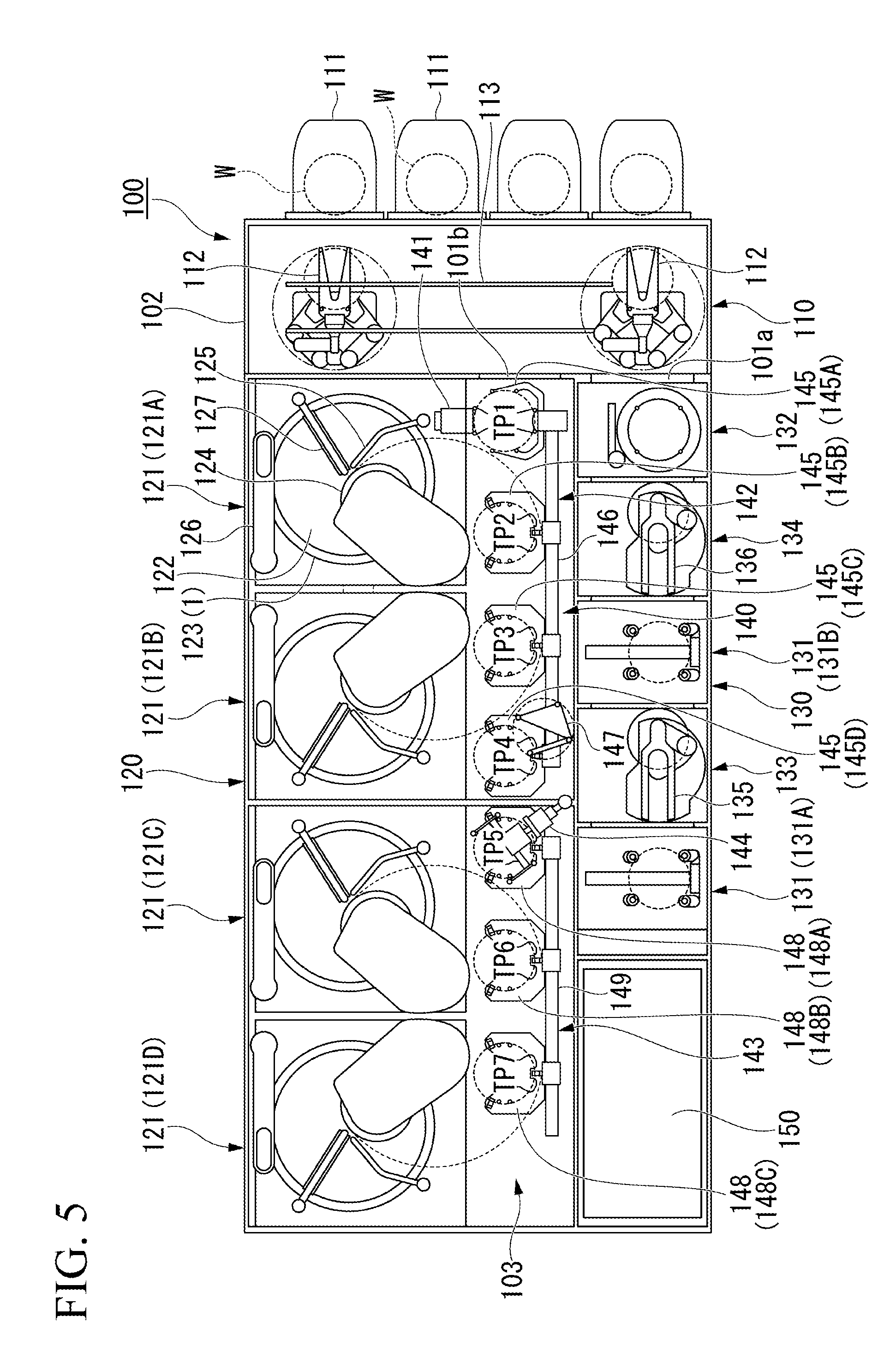
[0084] FIG. 5 is a plan view showing the overall configuration of the substrate processing apparatus 100 according to one embodiment.
[0085] The substrate processing apparatus 100 shown in FIG. 5 is a chemical mechanical polishing (CMP) apparatus that polishes the surface of a substrate W such as a silicon wafer in a flat manner. The substrate processing apparatus 100 includes a rectangular box-shaped housing 102. The housing 102 is formed in a substantially rectangular shape in plan view.
[0086] The housing 102 has a substrate transfer path 103 extending longitudinally at a center portion. A loader/unloader 110 is disposed at one end portion in a longitudinal direction of the substrate transfer path 103.
[0087] A polishing portion 120 is disposed on one side in the width direction (direction orthogonal to the longitudinal direction in plan view) of the substrate transfer path 103, and a cleaning portion 130 is disposed on the other side. In the substrate transfer path 103, a substrate transfer portion 140 transferring the substrate W is provided. Further, the substrate processing apparatus 100 includes a controller (control panel) 150 that controls operations of the loader/unloader 110, the polishing unit 120, the cleaning unit 130, and the substrate transfer unit 140.
[0088] The loader/unloader 110 includes a front loader 111 that accommodates the substrate W. A plurality of front loading portions 111 are provided on the side surface on one side in the longitudinal direction of the housing 102. The plurality of front loaders 111 are arranged in the width direction of the housing 102. For example, the front loader 111 mounts an open cassette, a Standard Manufacturing Interface (SMIF) pod, or a Front Opening Unified Pod (FOUP). SMIF and FOUP are airtight containers in which the cassette of the substrate W is accommodated and covered with partition walls, and it is possible to maintain an environment independent of the external space.
[0089] The loader/unloader 110 includes two transfer robots 112 for moving the substrate W in and out from the front loader 111, and a traveling mechanism 113 for moving each transfer robot 112 along the arrangement of the front loader 111. Each transfer robot 112 has two hands at the top and bottom, and is used selectively before and after the processing of the substrate W. For example, when the substrate W is returned to the front loading portion 111, the upper hand is used, and when removing the unprocessed substrate W from the front loading portion 111, the lower hand is used.
[0090] The polishing portion 120 includes a plurality of polishing units 121 (121A, 121B, 121C, and 121D) polishing (planarizing) the substrate W. The plurality of polishing units 121 are arranged in the longitudinal direction of the substrate transfer path 103. The polishing unit 121 includes a polishing table 123 that rotates the polishing pad 122 having a polishing surface, a top ring 124 that holds the substrate W and polishes the substrate W while pressing the substrate W against the polishing pad 122 on the polishing table 123, a polishing liquid supply nozzle 125 supplying a polishing liquid and a dressing liquid (for example, pure water) to the polishing pad 122, a dresser 126 performing dressing of the polishing surface of the polishing pad 122, and an atomizer 127 spraying a mixed fluid of liquid (for example, pure water) and a gas (for example, nitrogen gas), or liquid (for example, pure water) onto the polishing surface in a mist state.
[0091] The polishing unit 121 presses the substrate W against the polishing pad 122 by the top ring 124 while supplying the polishing liquid from the polishing liquid supply nozzle 125 onto the polishing pad 122, and relatively moves the top ring 124 and the polishing table 123, thereby, the substrate W is polished to make the surface flat. In the dresser 126, hard particles such as diamond particles or ceramic particles are fixed to the rotation portion at the tip contacting the polishing pad 122, and the dresser 126 swings while rotating the rotation portion, thereby, the entire polishing surface of the polishing pad 122 is dress uniformly to form a flat polished surface. The atomizer 127 washes away the polishing waste, abrasive grains, and the like remaining on the polishing surface of the polishing pad 122 with a high-pressure fluid to clean the polishing surface and to perform a dressing operation of the polished surface by the dresser 126 which performs with mechanical contact, to achieve polishing surface regeneration.
[0092] The cleaning unit 130 includes a plurality of cleaning units 131 (131A, 131B) for cleaning the substrate W and a drying unit 132 for drying the washed substrate W. The plurality of cleaning units 131 and the drying unit 132 (a plurality of processing units) are arranged in the longitudinal direction of the substrate transfer path 103. Between the cleaning unit 131A and the cleaning unit 131B, a first transfer chamber 133 is provided. In the first transfer chamber 133, a transfer robot 135 transferring the substrate W among the substrate transfer unit 140, the cleaning unit 131A, and the cleaning unit 131B is provided. In addition, a second transfer chamber 134 is provided between the cleaning unit 131B and the drying unit 132. In the second transfer chamber 134, a transfer robot 136 transferring the substrate W between the cleaning unit 131B and the drying unit 132 is provided.
[0093] The cleaning unit 131A includes, for example, a roll sponge type cleaning module to primarily clean the substrate W. In addition, the cleaning unit 131B also includes a roll sponge type cleaning module to secondarily clean the substrate W. It should be noted that the cleaning unit 131A and the cleaning unit 131B may be of the same type or a different type of cleaning module, and for example, may be even a pencil sponge type cleaning module or a two-fluid jet-type cleaning module. The drying unit 132 includes, for example, a drying module for performing Rotagoni drying (Iso-Propyl Alcohol (IPA) drying). After drying, the shutter 101a provided in the partition wall between the drying unit 132 and the loader/unloader 110 is opened, and the substrate W is taken out from the drying unit 132 by the transfer robot 112.
[0094] The substrate transfer unit 140 includes a lifter 141, a first linear transporter 142, a second linear transporter 143, and a swing transporter 144. In the substrate transfer path 103, a first transfer position TP1, a second transfer position TP2, a third transfer position TP3, a fourth transfer position TP4, a fifth transfer position TP5, a sixth transfer position TP6, and a seventh transfer position TP7 are set in this order from the side of the loader/unloader 110.
[0095] The lifter 141 is a mechanism transferring the substrate W upward and downward at the first transfer position TP1. The lifter 141 receives the substrate W from the transfer robot 112 of the loader/unloader 110 at the first transfer position TP1. Further, the lifter 141 transfers the substrate W received from the transfer robot 112 to the first linear transporter 142. A shutter 101b is provided on the partition wall between the first transfer position TP1 and the loader/unloader 110. When the substrate W is transferred, the shutter 101b is opened, the substrate W is received by the lifter 141 from the transfer robot 112.
[0096] The first linear transporter 142 is a mechanism that transfers the substrate W among the first transfer position TP1, the second transfer position TP2, the third transfer position TP3, and the fourth transfer position TP4. The first linear transporter 142 includes a plurality of transfer hands 145 (145A, 145B, 145C, and 145D) and a linear guide mechanism 146 that horizontally moves the respective transfer hands 145 at a plurality of heights. The transfer hand 145A moves between the first transfer position TP1 and the fourth transfer position TP4 by the linear guide mechanism 146. The transfer hand 145A is a pass hand for receiving the substrate W from the lifter 141 and transferring it to the second linear transporter 143. The transfer hand 145A is not provided with an elevation driving portion.
[0097] The transfer hand 145B moves between the first transfer position TP1 and the second transfer position TP2 by the linear guide mechanism 146. The transfer hand 145B receives the substrate W from the lifter 141 at the first transfer position TP1 and transfers the substrate W to the polishing unit 121A at the second transfer position TP2. The transfer hand 145B is provided with a lifting/lowering driving portion, which rises when delivering the substrate W to the top ring 124 of the polishing unit 121A, and descends after delivering the substrate W to the top ring 124. It is to be noted that the same elevation driving portion is also provided for the transfer hand 145C and the transfer hand 145D.
[0098] The transfer hand 145C moves between the first transfer position TP1 and the third transfer position TP3 by the linear guide mechanism 146. The transfer hand 145C receives the substrate W from the lifter 141 at the first transfer position TP1 and transfers the substrate W to the polishing unit 121B at the third transfer position TP3. The transfer hand 145C also functions as an access hand that receives the substrate W from the top ring 124 of the polishing unit 121A at the second transfer position TP2 and delivers the substrate W to the polishing unit 121B at the third transfer position TP3.
[0099] The transfer hand 145D moves between the second transfer position TP2 and the fourth transfer position TP4 by the linear guide mechanism 146. The transfer hand 145D functions as an access hand that receives the substrate W from the polishing unit 121A or the top ring 124 of the polishing unit 121B at the second transfer position TP2 or the third transfer position TP3, and receives the substrate W at the swing transporter 144 at the fourth transfer position TP4.
[0100] The swing transporter 144 has a hand movable between the fourth transfer position TP4 and the fifth transfer position TP5, and transfers the substrate W from the first linear transporter 142 to the second linear transporter 143. Further, the swing transporter 144 delivers the substrate W polished by the polishing portion 120 to the cleaning portion 130. On the side of the swing transporter 144, a temporary placement table 147 of the substrate W is provided. The swing transporter 144 places the substrate W received at the fourth transfer position TP4 or the fifth transfer position TP5 upside down and mounts the substrate W on the temporary stage 147. The substrate W placed on the temporary placement stand 147 is transferred to the first transfer chamber 133 by the transfer robot 135 of the cleaning unit 130.
[0101] The second linear transporter 143 is a mechanism that transfers the substrate W among the fifth transfer position TP5, the sixth transfer position TP6, and the seventh transfer position TP7. The second linear transporter 143 includes a plurality of transfer hands 148 (148A, 148B, and 148C) and a linear guide mechanism 149 for horizontally moving the transfer hands 145 at a plurality of heights. The transfer hand 148A moves from the fifth transfer position TP5 to the sixth transfer position TP6 by the linear guide mechanism 149. The transfer hand 145A functions as an access hand that receives the substrate W from the swing transporter 144 and transfers it to the polishing unit 121C.
[0102] The transfer hand 148B moves between the sixth transfer position TP6 and the seventh transfer position TP7. The transfer hand 148B functions as an access hand for receiving the substrate W from the polishing unit 121C and delivering it to the polishing unit 121D. The transfer hand 148C moves between the seventh transfer position TP7 and the fifth transfer position TP5. The transfer hand 148C functions as an access hand for receiving the substrate W from the polishing unit 121C or the top ring 124 of the polishing unit 121D at the sixth transfer position TP6 or the seventh transfer position TP7, and receives the substrate W on the swing transporter 144 at the fifth transfer position TP5. Although the explanation is omitted, the operation when the transfer hand 148 transfers the substrate W is the same as the above-described operation of the first linear transporter 142.
[0103] Also in the substrate processing apparatus 100 having the above configuration, by applying the above-described polishing table 1 of the present invention and its drainage and exhaust structure 10 to the polishing table 123 of the polishing unit (polishing apparatus) 121, the cleanness around the polishing table 123 can be further improved.
Second Embodiment
(Polishing Apparatus)
[0104] FIG. 6 is a configuration diagram of a polishing table 1 and its peripheral structure included in the polishing apparatus according to one embodiment. FIG. 7 is a plan view of the polishing table 1 according to one embodiment. FIG. 8 is an explanatory view showing the internal structure of the shaft 9 according to one embodiment.
[0105] In the present embodiment, different portions will be described based on the polishing apparatus of the first embodiment, and description of the same portions will be omitted.
[0106] In the heat medium flow path 4 of the present embodiment, from a side of a rotary joint 9a described later, a heat medium (such as temperature controlled water) is supplied through the shaft 9. The heat medium, as shown in FIG. 7, is supplied from a supply port 2A at a center portion of the table 2 and is discharged from the two discharge ports 2B at a center portion of the table 2. Specifically, the heat medium is supplied from the supply port 2A and flows radially and outwardly of the table 2, and branches radially inward and radially outward at the intermediate portion 2I thereof. After circulating radially inward and radially outward respectively, the heat medium is discharged from the two discharge ports 2B. As a result, the temperature of the upper surface of the table 2 can be uniformized efficiently.
[0107] In the polishing table 1, almost the entire upper surface of the table 2 is used for polishing, so that uniformization of the temperature of the upper surface of the table 2 is important as a polishing condition. Also, the uniformization of the temperature of the upper surface of the table 2 is important in terms of prolonging the life of the polishing table 1 and the polishing pad (not shown). That is, if the temperature of the upper surface of the table 2 cannot be made uniform and as the temperature distribution increases, the difference in local expansion and contraction of the coating film (not shown) of the table 2 and the difference in local expansion and contraction between the coating film and the table 2 increases. This causes cracks and peeling occur as deterioration of the film.
[0108] As the table 2, the following materials are suitable. For example, when the material of the table 2 is SiC (silicon carbide), the minimum tensile strength is 450 (MPa) which shows that the workability is excellent, the mechanical strength is sufficient, and the thermal conductivity is high as 170 (W/(mK)), and it is suitable for temperature control.
[0109] In addition, the table 2 can also be made of aluminum which is easy for machine processing. For example, when the material of the table 2 is an aluminum alloy plate of A6061P, the minimum tensile strength is 310 (MPa) which shows that the workability is excellent, the mechanical strength is sufficient, and the thermal conductivity is high as 167 (W/(mK)), and it is suitable for temperature control.
[0110] Further, for example, when the material of the table 2 is an aluminum alloy casting of AC4CH, the minimum tensile strength is 230 (MPa) which shows that the workability is excellent, the mechanical strength is sufficient, and the thermal conductivity is high as 151 (W/mK)), and it is suitable for temperature control. On the other hand, in the case of SUS 304 which is common as a mechanical material, the mechanical strength is sufficient with a minimum tensile strength of 520 (MPa); however, the thermal conductivity is low as 17 (W/(mK)) and it requires a high degree of machining such that the heat medium flow path 4 has to be formed with a milling machine. Therefore, it cannot be said that it is a material excellent in workability; however, it has high toughness of materials and can be an option.
[0111] On the upper surface side of the peripheral portion of the table 2, a step 2c is provided. The depth of the step 2c is determined such that the sum of the thickness of the flinger (water drain member) 11 described later and the head height of the bolt 2d for attaching the flinger 11 and the table 2 to the table base 3 is below an upper surface position of the first table portion 2a.
[0112] As shown in FIG. 7, a plurality of bolts (twelve in the illustrated example) 2d are arranged on the same radius of the peripheral portion of the table 2 with a predetermined interval therebetween. In the plurality of bolts 2d, as shown in FIG. 6, the peripheral edge portion of the table 2 is detachably fixed to the peripheral edge portion of the table base 3 through the flinger 11. That is, if these bolts 2d are removed, the table 2 and the flinger 11 can be removed from the table base 3.
[0113] The upper end portion of the shaft 9 passing through the hollow motor rotation shaft 7a of the motor 7 is connected to the center of the lower surface portion of the polishing table 1. The lower end portion of the shaft 9 is connected to the rotary joint rotation shaft 9d of the rotary joint 9a via a heat medium flange 9k fixed to the lower end portion of the motor rotation shaft 7a. Therefore, the shaft 9 above the rotary joint 9a can rotate with the table 2. The rotary joint 9a is connected to a heat-medium supply pipe 9b supplying a heat medium to the shaft 9 side and a heat medium return pipe 9c returning the heat medium discharged from the shaft 9 side.
[0114] Inside the shaft 9, pipes as shown in FIG. 8 are included. The pipe 9f is arranged concentrically with the center axis L. On both sides of the pipe 9f are provided with a pipe line 9g supplying the heat medium supplied from the heat-medium supply pipe 9b of the rotary joint 9a to the heat medium flow path 4 in the table 2, and a pipe line 9h (disposed on the back side in FIG. 8) discharging the heat medium discharged from the heat medium flow path 4 to the heat-medium returning pipe 9c of the rotary joint 9a.
[0115] The upper portion (head 9j) of the pipe 9f and pipelines 9g and 9h is connected (inserted) to a bush 3d provided on the bottom side of the table base 3. The head 9j is formed in a two-stage column such that an upper portion has a small diameter and a lower portion has a large diameter. At the vertical two positions on the peripheral surface of the small-diameter column and one position under the peripheral surface of the large-diameter column, an O-ring is provided (refer to a bold line in FIG. 8). The heat medium from the pipe line 9g is supplied from the small-diameter column to the heat medium flow path 4 through a flow path (not shown), and the heat medium discharged from the heat medium flow path 4 is discharged from the large-diameter column to the pipe line 9h through a flow path (not shown).
[0116] On the other hand, the lower portion of the pipe 9f and the pipe lines 9g and 9h is supported by a heat medium flange 9k. The heat medium flange 9k is fixed to the lower end portion of the motor rotation shaft 7a and is connected to the rotary joint rotation shaft 9d of the rotary joint 9a. Therefore, when a heat medium is supplied to the heat-medium supply pipe 9b of the rotary joint 9a, the supplied heat medium passes through the heat medium flow path 4 in the table 2 via the heat medium flange 9k, the pipe line 9g, and the small-diameter column of the head 9j. Then, the heat medium can return to the heat-medium returning pipe 9c of the rotary joint 9a via the large-diameter column of the head 9j, the pipe line 9h, and the heat medium flange 9k.
[0117] For example, when the temperature of the table 2 has not yet reached the predetermined temperature at the start of operation of the polishing apparatus, the temperature adjustment of the table 2 is performed so as to raise the temperature of the table 2, that is, a heat medium may be supplied to heat the table 2. When the operation of the polishing apparatus proceeds and the temperature of the table 2 becomes higher than the predetermined temperature due to the frictional heat caused by polishing, it is preferable to supply the heat medium so as to cool the table 2. In this manner, by constantly adjusting the temperature of the table 2 to a constant temperature, substrate polishing with high yield can be performed.
[0118] On the flange 6, a branch pipe 9i is provided. The branch pipe 9i is used for power supply lines of the wafer film thickness detector 5 and piping for signal conductors. These wires are guided to the side of the rotary joint 9a via a pipe 9f. Therefore, although not shown, a mechanism of a rotary connector is attached to the lower portion of the rotary joint 9a so that power supply and detection signals can be taken out.
[0119] In this embodiment, the flinger 11 shown in FIG. 6 is provided in the step 2c of the table 2. The overall shape of the flinger 11 is formed in a cylindrical shape that can cover the entire side of the table 2 and the division surface D of the table 2 and the table base 3. The vertical cross-sectional shape of the flinger 11 is such that the L-shaped top and bottom are reversed, and the upper bent portion of such form is attached to the step 2c of the table 2. The length of the portion vertically descending from the bent portion is determined so as to extend downward from the lower end position of the water drain protrusion 3a provided on the table base 3.
[0120] As described above, according to the present embodiment described above, the polishing table 1 is provided that is pressed against the upper surface and rotated around the central axis L. The polishing table 1 includes the table 2 having a heat medium flow path 4 therein and forms the upper surface, and a table base 3 detachably supporting the table 2. According to such a configuration, since only the table 2 having the heat medium flow path 4 can be partially replaced according to the purpose of the temperature control, the specification of the polishing table 1 can be changed at low cost.
[0121] For example, the table 2 can also be formed from a material having better processability than the table base 3 (for example, when the table base 3 is made of stainless steel, the table 2 is made of aluminum, ceramics, or the like having better processability than stainless steel). Further, it is also possible to cope with replacement of the table 2 based on deterioration of the surface of the table 2 due to long-term use (for example, when the material is aluminum, rust and the like can occur).
[0122] In the present embodiment, as shown in FIGS. 6 and 7, a plurality of bolts 2d detachably fixing the peripheral portion of the table 2 to the peripheral edge portion of the table base 3, and at a radially inward side of the plurality of bolts 2d, one or a plurality of knock pins 3b positioning the table 2 with respect to the table base 3 are included. Therefore, it is possible to easily remove the table 2 from the table base 3 together with the flinger 11 by detaching the bolt 2d. Further, at the time of attachment, since the table 2 is positioned with respect to the table base 3 via not only the plurality of bolts 2d but also one or a plurality of knock pins 3b arranged radially inward, even if the separate structure of the table 2 and the base 3 is adopted, it can rotate in the same manner as the integral structure.
[0123] Furthermore, in the present embodiment, there is provided a tubular flinger 11 which covers the division surface D between the table 2 and the table base 3 from the radially outer side, and the flinger 11 is detachably attached to the peripheral portion of the polishing table 1 by a plurality of bolts 2d. Therefore, it is possible to prevent liquid from entering the division surface D between the table 2 and the table base 3.
[0124] A cylindrical flange 6 rotatably driven by a motor 7 is connected to the lower surface side of the table base 3. The flange 6 forms a space for attaching the wafer film thickness detector 5 on the lower surface side of the table base 3 that measures the film thickness of the substrate. Since the annular drain protrusion 3a protruding downward is formed on the lower surface side of the peripheral portion of the table base 3, water-wetting of the wafer film thickness detector 5 due to the flow of the liquid to the lower surface side of the table base 3 and the like can be prevented.
(Substrate Processing Apparatus)
[0125] As a substrate processing apparatus, the substrate processing apparatus 100 of the first embodiment is used.
[0126] Also in the substrate processing apparatus 100 having the above configuration, by applying the above-described polishing table 1 of the present invention to the polishing table 123 of the polishing unit (polishing apparatus) 121, the specification of the polishing table 123 can be changed in low cost according to the purpose of temperature adjustment.
(Attachment Structure of Polishing Pad)
[0127] Subsequently, an attachment structure of the polishing pad 122 to be attached to the polishing table 123 having the above-described structure will be described.
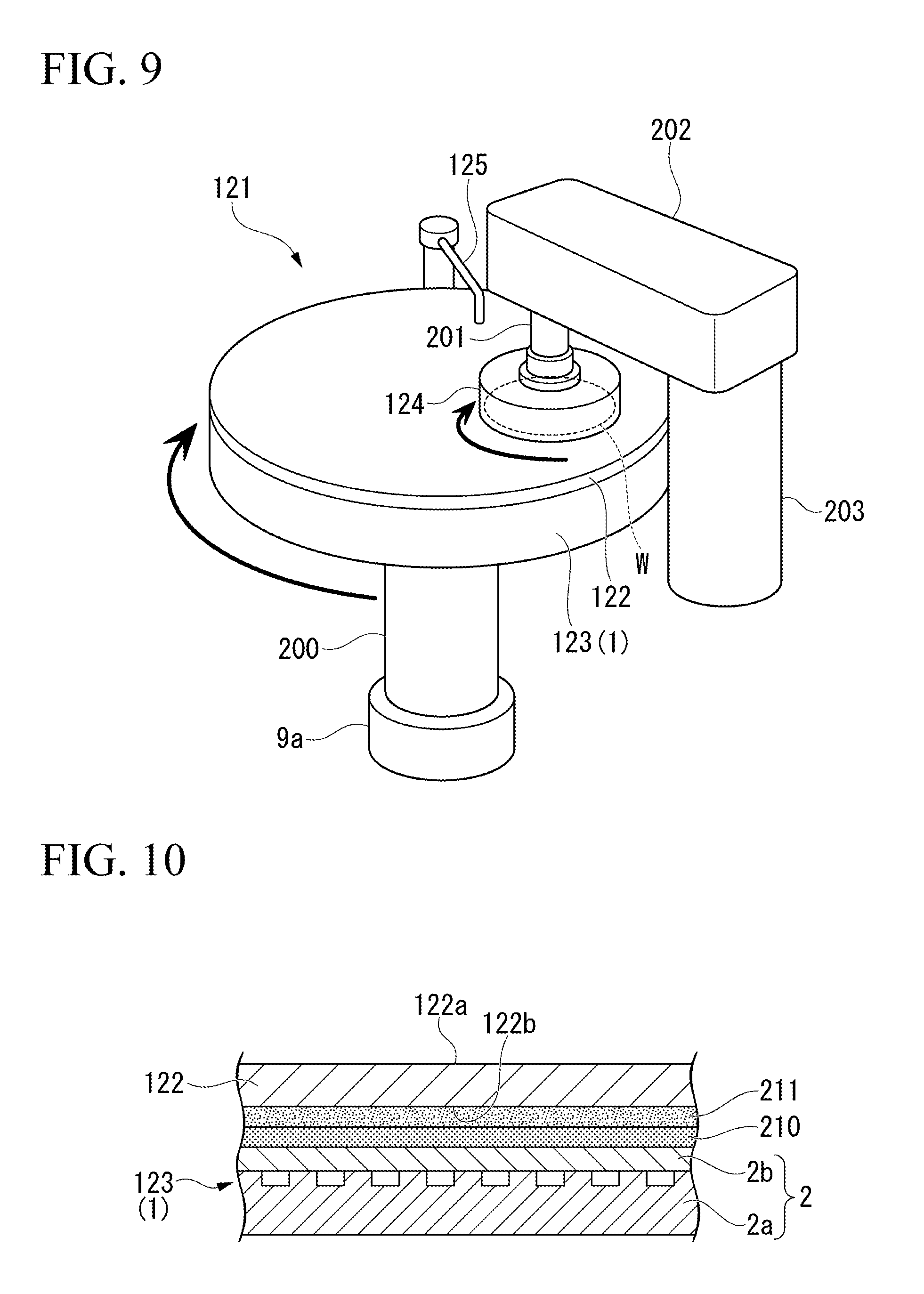
[0128] FIG. 9 is a schematic perspective view showing the entire configuration of the polishing unit 121 shown in FIG. 5.
[0129] As shown in FIG. 9, the polishing unit 121 includes a polishing table 123 and a top ring 124 that holds the substrate W being an object to be polished and presses against the polishing pad 122 on the polishing table 123. The polishing table 123 is connected to a hollow table shaft 200 (flange 6 shown in FIG. 6 described above). The table shaft 200 is coupled to a polishing table rotation motor (motor 7 shown in FIG. 6 described above, not shown in FIG. 9), and the polishing table 123 is rotatable integrally with the table shaft 200. The polishing table 123 shown in FIG. 9 is based on the above-described structure of the polishing table 1 (the divided structure of the table 2 (laminated structure)); however, the attachment structure (monolayer structure) of the polishing pad 122 can be adapted to a conventional polishing table of the table 2.
[0130] A polishing pad 122 is affixed to the upper surface of the polishing table 123, and the surface of the polishing pad 122 constitutes a polishing surface for polishing the substrate W. As the polishing pad 122, roughly three types such as a hard foaming type, a nonwoven fabric type, and a suede type polishing pad can be used.
[0131] The rigid foam type is a pad including vacancies, which is generally made of polyurethane. The nonwoven fabric type is a nonwoven fabric such as polyester impregnated with urethane or the like. The suede type is applied to the base material by wet molding, and as a base material, a product using a nonwoven fabric similar to that used for the nonwoven fabric pad and a product using PET (polyethylene terephthalate) is there. The base material was prepared by coating a DMF (dimethylformamide) solution of a urethane resin, substituting coagulant (water) and DMF, and pores were exposed on the surface.
[0132] A polishing liquid supply nozzle 125 is installed above the polishing table 123, and a polishing liquid (slurry) is supplied to the polishing pad 122 on the polishing table 123 by the polishing liquid supply nozzle 125. In the polishing table 123, a flow path for the heat exchange medium (heat medium flow path 4 shown in FIG. 6 described above, not shown in FIG. 9 described above) is provided.
[0133] Heat exchange is performed between the heat exchange medium and the polishing table 123 by flowing cooling water as a heat exchange medium in the flow path for the heat exchange medium to prevent thermal deformation of the polishing table 123 due to frictional heat during polishing and the surface temperature of the polishing table 123 is adjusted. Therefore, as shown in FIG. 9, the rotary joint 9a is disposed in the lower portion of the table shaft 200, cooling water is supplied from outside to the cooling water pipe (not shown) and a flow path of the polishing table 123 through the rotary joint 9a.
[0134] The top ring 124 is connected to the top ring shaft 201, and the top ring shaft 201 moves up and down with respect to the support arm 202. By vertically moving the top ring shaft 201, the entire top ring 124 is vertically moved with respect to the support arm 202 so as to be positioned. The top ring shaft 201 is configured to rotate by driving a top ring rotation motor (not shown). By the rotation of the top ring shaft 201, the top ring 124 rotates around the top ring shaft 201.
[0135] The top ring 124 can hold the substrate W on the lower surface thereof. The support arm 202 is configured to be rotatable around the shaft 203, and the substrate W is vacuum-sucked which is transferred to a substrate reception position (the second transfer position TP2, the third transfer position TP3, the sixth transfer position TP6, and the seventh transfer position TP7 shown in FIG. 5). The top ring 124 holding the substrate W on the lower surface thereof is movable upward of the polishing table 123 by the rotation of the support arm 202.
[0136] The top ring 124 holds the substrate W on the lower surface thereof and presses the substrate W against a surface of the polishing pad 122. At this time, each of the polishing table 123 and the top ring 124 is rotated, and a polishing liquid (slurry) is supplied onto the polishing pad 122 from a polishing liquid supply nozzle 125 provided above the polishing table 123. As the polishing liquid, the polishing liquid including silica (SiO.sub.2) or ceria (CeO.sub.2) as abrasive grains can be used. While supplying the polishing liquid onto the polishing pad 122 in this manner, the substrate W is polished by pressing the substrate W against the polishing pad 122 by the top ring 124 to relatively move the substrate W and the polishing pad 122. During polishing, relative movement (for example, swing (rotation)) other than rotation of the substrate W and the polishing pad 122 may be performed. As a result, deterioration of the same portion of the polishing pad 122 is prevented.
[0137] Meanwhile, as shown in FIG. 10 described later, the polishing pad 122 is adhered to the table 2 via the adhesive layer 211. When a large number of samples (substrate W) are polished, the polishing pad 122 causes deterioration of polishing performance, uneven polished surface, accumulation of foreign matters, and the like, so that it is necessary to perform a replacement the polishing pad 122 periodically or based on the number of polishing times. At that time, if the adhesion of the polishing pad 122 is strong, much labor and time are required for the replacing operation. Therefore, the polishing table 123 of the present embodiment has a structure for adhering the polishing pad 122 as shown in FIG. 10.
[0138] FIG. 10 is a cross-sectional view showing an attachment structure of the polishing pad 122 according to one embodiment.
[0139] As shown in FIG. 10, on the upper surface of the table 2 forming the polishing table 123, a coating layer 210 to which the polishing pad 122 is releasably adhered is formed. An adhesive layer 211 is formed on the back surface 122b of opposite to the polishing surface 122a the polishing pad 122. In other words, the coating layer 210 is interposed between the table 2 and the polishing pad 122, and the adhesive layer 211 is interposed between the coating layer 210 and the polishing pad 122.
[0140] That is, the adhesive layer 211 may be formed on the upper surface of the coating layer 210. Here, the term "adhesion" of the adhesive layer 211 includes "sticky adhesion".
[0141] The adhesive forming the adhesive layer 211 is not particularly limited, and examples thereof include a pressure sensitive adhesive, a hot melt adhesive, and the like, and a hot melt adhesive is preferable. One type of adhesive may be used alone, or two or more types may be mixed and used. The hot melt adhesive is not particularly limited, and known materials can be used without particular limitation. In addition to hot melt adhesives and pressure sensitive adhesives, instead of or in combination with hot melt adhesives and pressure sensitive adhesives, two-component curing epoxy type adhesives, silicone type adhesives, and the like may be used. In addition to the pressure sensitive adhesive and the hot melt adhesive, an acrylic adhesive, a silicone adhesive or a double coated tape may be used.
[0142] As the material forming the table 2, the above-mentioned metal (aluminum (alloy) or stainless steel), ceramic, synthetic resin may be used. Further, the surface of the aluminum (alloy) table 2 may be covered with aluminum oxide or a nickel coating. The surface hardness of the table 2 can be increased by aluminum oxide and nickel coating. In addition, in the case where the table 2 is made of aluminum (alloy), if there is a heat medium flow path 4 for temperature control or other mechanism (temperature control device and the like) in the table 2, since aluminum (alloy) has high thermal conductivity, temperature controllability and contribution to stabilization of polishing performance are increased. Further, a flow path for discharging the slurry may be formed on the upper surface of the table 2.
[0143] The coating layer 210 is formed from a low adhesive material so that the polishing pad 122 can be replaced with effortless in order to easily, efficiently, and safely replace the polishing pad 122. Here, the "low adhesion" of the low adhesion material refers to "facilitating peeling of the polishing pad 122", and does not refer to low or high adhesiveness or the like with respect to a specific material. The coating layer 210 also has a function of preventing the contact between the oxide film described above and the polishing liquid or the like to prevent corrosion of the table 2 so as to favorably maintain the adhesion state of the polishing pad 122.
[0144] As the low adhesion material for forming the coating layer 210, fluororesin (PTFE (polytetrafluoroethylene), PCTFE (polychlorotrifluoroethylene), PVDF (polyvinylidene fluoride), FEP (tetrafluoroethylene.hexafluoride propylene copolymer), or PFA (perfluoroalkoxy fluorine resin) is preferable. Depending on the polishing conditions (kind of polishing liquid, kind of polishing pad, and the like), polyamide resin, phenol resin, or polyester resin may be used. Examples of coating means for such a coating layer 210 include electrostatic spraying, hot melt spraying, cementing, and the like.
[0145] The thickness of the coating layer 210 is preferably, for example, 100 .mu.m or less. In consideration of the adhesiveness of the coating material and the peeling property of the adhesive that can be used for the material, the surface roughness of the coating layer 210 is controlled to make the contact or adhesion to the polishing pad 122 sufficient. In addition, the coating layer 210 may have a plurality of layers such as two, three or more layers as well as one layer. According to such a coating layer 210 (fluororesin coating layer), since the friction coefficient of the surface is low, it becomes easy to peel off the polishing pad 122 from the upper surface of the table 2. Therefore, it is possible to replace the polishing pad 122 more safely, quickly, and easily.
[0146] The coating layer 210 may be a glass coating layer, a ceramic coating layer, or a diamond coating layer. Since the coating layer 210 is harder and has less deformation than the resin coating layer such as the fluororesin coating layer described above, the polishing pad 122 is easy to peel off, and removal of residual adhesive is also easy. In addition, since the surface is harder than the resin coating layer and its deformation is small, it is possible to extend the life of the table 2 with respect to repeated replacement of the polishing pad 122.
[0147] Furthermore, in the case of the resin coating layer, it takes time to peel off the coating layer and the re-paint (adhere) operation at the time of maintenance on the coated surface (upper surface of the table 2); however, periodically performing maintenance by a minute amount of polishing of the coated surface can guarantee flatness and cleanliness of the coated surface, and the service life of the table 2 can be extended. The polishing method of maintaining the coated surface may be carried out by not separately placing the polishing apparatus and attaching a polishing member dedicated to the coated surface polishing to the dresser 126 (see FIG. 5) of the polishing unit 121.
[0148] As described above, according to the above-described embodiment, the polishing pad 122 which is a polishing apparatus for planarizing the substrate W and has the polishing surface 122a, the top ring 124 for holding (pressing) the substrate W on the polishing surface 122a, a transfer device (top ring rotation motor, support arm 202, and the like) for moving (relative displacement) the table 2 (polishing table 123) and the top ring 124 to polish the substrate W, and the table 2 having a first surface (upper surface) for adhesion of the polishing pad 122 are provided, and the table 2 includes a coating layer 210 of low adhesion material on an upper surface thereof. By employing such a structure, the replacement operation of the polishing pad 122 can be performed safely, simply, and efficiently without effort.
[0149] As described above, in the present invention, in the polishing apparatus polishing various specimens (substrate W) held by the top ring 124 while using the polishing liquid that matches each specimen to relatively move the specimen with respect to the polishing pad 122, service life of the polishing table 123 and the polishing pad 122 are prolonged. In order to prolong the service life of the table 2, in consideration of polishing performance in the table 2, it is preferable to provide the polishing table 1 (see FIG. 6) having the replaceable upper surface of the present invention, that is, to provide a divided structure of the table 2. Further, the divided structure of the table 2 includes a structure for actively discharging the used polishing liquid from the polishing table 1 and a structure for attaching the outer peripheral portion of the polishing table 1 so as not to cause deterioration of material due to the polishing liquid or contamination of the polishing liquid (see FIGS. 6 and 4). Thereby, it is possible to prevent the polishing liquid from entering the divided surface D. In addition, when using the polishing pad 122, it is necessary to satisfy both contradictory aspects, that is, maintenance of its function (adhesiveness) and ease of the replacement operation (releasability). In consideration of the resistance to the polishing liquid of the polishing pad 122 and the table 2 under the polishing pad 122, as shown in FIG. 10, it is preferable to provide the coating layer 210, which is particularly preferable to be fluororesin, glass, ceramic, or diamond.
[0150] While preferred embodiments of the present invention have been described and illustrated, it is understood that these are examples of the invention and should not be considered as limiting. Additions, omissions, substitutions, and other changes can be made without departing from the scope of the present invention. Accordingly, the invention should not be regarded as limited by the foregoing description; however, limited by the claims.
[0151] For example, in the above embodiments, a configuration in which the polishing apparatus of the present invention is applied to the polishing portion 120 of the substrate processing apparatus 100 (chemical mechanical polishing (CMP) apparatus) has been exemplified; however, the present invention is not limited to the CMP apparatus, but also applied to a substrate processing apparatus (for example, a back surface polishing apparatus, a bevel polishing apparatus, an etching apparatus, or a plating apparatus).
* * * * *
D00000
D00001
D00002
D00003
D00004
D00005
D00006
D00007
D00008
D00009
XML
uspto.report is an independent third-party trademark research tool that is not affiliated, endorsed, or sponsored by the United States Patent and Trademark Office (USPTO) or any other governmental organization. The information provided by uspto.report is based on publicly available data at the time of writing and is intended for informational purposes only.
While we strive to provide accurate and up-to-date information, we do not guarantee the accuracy, completeness, reliability, or suitability of the information displayed on this site. The use of this site is at your own risk. Any reliance you place on such information is therefore strictly at your own risk.
All official trademark data, including owner information, should be verified by visiting the official USPTO website at www.uspto.gov. This site is not intended to replace professional legal advice and should not be used as a substitute for consulting with a legal professional who is knowledgeable about trademark law.