Microfluidic Device For Fluid Mixture
MARKEL; David ; et al.
U.S. patent application number 16/303095 was filed with the patent office on 2019-10-03 for microfluidic device for fluid mixture. This patent application is currently assigned to Hewlett-Packard Development Company, L.P.. The applicant listed for this patent is HEWLETT-PACKARD DEVELOPMENT COMPANY, L.P.. Invention is credited to Ning GE, Alexander GOVYADINOV, Diane R HAMMERSTAD, Pavel KORNILOVICH, David MARKEL, Viktor SHKOLNIKOV, Erik D TORNIAINEN.
| Application Number | 20190299176 16/303095 |
| Document ID | / |
| Family ID | 60912950 |
| Filed Date | 2019-10-03 |
View All Diagrams
| United States Patent Application | 20190299176 |
| Kind Code | A1 |
| MARKEL; David ; et al. | October 3, 2019 |
MICROFLUIDIC DEVICE FOR FLUID MIXTURE
Abstract
Examples include microfluidic devices. Example microfluidic devices comprise a first microfluidic channel, a second microfluidic channel, and microfluidic output channel fluidly coupled to the first microfluidic channel and the second microfluidic channel via a fluid junction. The example device comprises a first fluid actuator disposed in the first microfluidic channel to actuate to thereby pump a first fluid into the microfluidic output channel, and the example device comprises a second fluid actuator disposed in the second microfluidic channel to actuate to pump a second fluid into the microfluidic output channel. The first fluid actuator and the second fluid actuator are to actuate to thereby pump a fluid mixture of the first fluid and the second fluid into the microfluidic output channel.
| Inventors: | MARKEL; David; (Corvallis, OR) ; KORNILOVICH; Pavel; (Corvallis, OR) ; TORNIAINEN; Erik D; (Corvallis, OR) ; GOVYADINOV; Alexander; (Corvallis, OR) ; SHKOLNIKOV; Viktor; (Palo Alto, CA) ; HAMMERSTAD; Diane R; (Corvallis, OR) ; GE; Ning; (Palo Alto, CA) | ||||||||||
| Applicant: |
|
||||||||||
|---|---|---|---|---|---|---|---|---|---|---|---|
| Assignee: | Hewlett-Packard Development
Company, L.P. Houston TX |
||||||||||
| Family ID: | 60912950 | ||||||||||
| Appl. No.: | 16/303095 | ||||||||||
| Filed: | June 30, 2017 | ||||||||||
| PCT Filed: | June 30, 2017 | ||||||||||
| PCT NO: | PCT/US2017/040418 | ||||||||||
| 371 Date: | November 19, 2018 |
Related U.S. Patent Documents
| Application Number | Filing Date | Patent Number | ||
|---|---|---|---|---|
| PCT/US2016/041586 | Jul 8, 2016 | |||
| 16303095 | ||||
| Current U.S. Class: | 1/1 |
| Current CPC Class: | B01F 13/0059 20130101; B01F 2215/0036 20130101; G01N 35/1095 20130101; B01F 15/0416 20130101; B01F 2215/0037 20130101; B01L 3/5027 20130101; B01L 2300/1827 20130101; F04B 19/006 20130101; B01L 2300/0867 20130101; B41J 2/1433 20130101; B81B 1/00 20130101; F04B 19/00 20130101; B01D 15/166 20130101; B41J 2/175 20130101; B01L 3/50273 20130101; B01L 2400/082 20130101; B01F 15/0258 20130101; B01L 2400/0415 20130101; B01F 13/0064 20130101; B01L 2400/0487 20130101; B01L 2200/06 20130101; B01F 15/0243 20130101; B01L 2400/0439 20130101; B01L 2400/0442 20130101; B01F 15/0408 20130101 |
| International Class: | B01F 13/00 20060101 B01F013/00; B01F 15/04 20060101 B01F015/04; B41J 2/14 20060101 B41J002/14; B01L 3/00 20060101 B01L003/00 |
Claims
1. A microfluidic device comprising: a first microfluidic channel; a second microfluidic channel; a microfluidic output channel fluidly coupled to the first microfluidic channel and the second microfluidic channel at a fluid junction; a first fluid actuator disposed in the first microfluidic channel, the first fluid actuator to actuate to thereby pump a first fluid into the microfluidic output channel; and a second fluid actuator disposed in the second microfluidic channel, the second fluid actuator to actuate to thereby pump a second fluid into the microfluidic output channel, and the first fluid actuator and second fluid actuator to actuate to thereby pump a fluid mixture of the first fluid and the second fluid into the microfluidic output channel.
2. The microfluidic device of claim 1, further comprising: a first fluid input fluidly coupled to the first microfluidic channel to input the first fluid; a second fluid input fluidly coupled to the second microfluidic channel to input the second fluid; and a microfluidic chamber fluidly coupled to the microfluidic output channel to store the fluid mixture.
3. The microfluidic device of claim 1, wherein the first fluid and the second fluid have at least one different fluid characteristic, the at least one different fluid characteristic comprising at least one of: vapor pressure, temperature, viscosity, surface tension, and heat of vaporization, and the first microfluidic channel and the second microfluidic channel have at least one different microfluidic channel characteristic, the at least one different microfluidic channel characteristic comprising at least one of: channel width, microfluidic channel cross-sectional area, microfluidic channel geometry, microfluidic channel length, channel surface roughness.
4. The microfluidic device of claim 1, further comprising: a controller coupled to the first fluid actuator and the second fluid actuator, the controller to: selectively actuate the first fluid actuator and the second fluid actuator.
5. The microfluidic device of claim 4, wherein the controller to selectively actuate the first fluid actuator and the second fluid actuator comprises the controller to: actuate the first fluid actuator according to first actuation characteristics; and actuate the second fluid actuator according to second actuation characteristics, wherein the first actuation characteristics and the second actuation characteristics differ with respect to at least one of frequency of actuation, duration of actuation, number of pulses of actuation, phase offset of actuation, and intensity of actuation.
6. The microfluidic device of claim 4, wherein the controller is to selectively actuate the first fluid actuator and the second fluid actuator asynchronously such that the fluid mixture comprises a first concentration of the first fluid and a second concentration of the second fluid.
7. The microfluidic device of claim 4, further comprising: at least one fluid sensor, wherein the controller is further to: detect a flow rate with the at least one fluid sensor, wherein the controller is to selectively actuate at least one of the first fluid actuator and the second fluid actuator based at least in part on the flow rate.
8. The microfluidic device of claim 7, wherein the at least one fluid sensor comprises at least one of: a first fluid sensor disposed in the first microfluidic channel, a second fluid sensor disposed in the second microfluidic channel, and a third fluid sensor disposed in the microfluidic output channel.
9. (canceled)
10. The microfluidic device of claim 1, wherein the microfluidic output channel is fluidly coupled to at least one of: a microfluidic reaction chamber, an ejection chamber; a chromatography column, and an optical detection chamber.
11. The microfluidic device of claim 1, wherein the first fluid actuator is to pump the first fluid towards the fluid junction at a first flow rate, the microfluidic device further comprising: a third fluid actuator disposed in the first microfluidic channel to actuate to thereby pump the first fluid towards the fluid junction at a second flow rate.
12. The microfluidic device of claim 1, wherein the first fluid actuator corresponds to a first inertial pump disposed in the first microfluidic channel, the second fluid actuator corresponds to a second inertial pump disposed in the second microfluidic channel, and each of the first fluid actuator of the first inertial pump and the second fluid actuator of the second inertial pump are thermal resistors.
13. A microfluidic device comprising: a first microfluidic channel; a second microfluidic channel; a microfluidic output channel that is fluidly coupled to the first microfluidic channel and the second microfluidic channel at a fluid junction; a first at least one fluid actuator disposed in the first microfluidic channel, the first at least one fluid actuator to actuate to thereby pump a first fluid into the microfluidic output channel; a second at least one fluid actuator disposed in the second microfluidic channel, the second at least one fluid actuator to actuate to thereby pump a second fluid into the microfluidic output channel, and the first at least one fluid actuator and the second at least one fluid actuator to asynchronously actuate to thereby pump fluid into the microfluidic output channel to thereby pump a fluid mixture of the first fluid and the second fluid into the microfluidic output channel.
14. (canceled)
15. The microfluidic device of claim 13, wherein the first at least one fluid actuator comprises a first set of fluid actuators, the microfluidic device further comprising: a controller coupled to each fluid actuator of the first set of fluid actuators, the controller to: actuate a particular fluid actuator of the first set of fluid actuators to cause the particular fluid actuator to pump a first volume of the first fluid into the microfluidic output channel; and actuate the particular fluid actuator and at least one other fluid actuator of the first set of fluid actuators synchronously to cause the particular fluid actuator and the at least one other fluid actuator to pump a second volume of the first fluid into the microfluidic output channel.
16. The microfluidic device of claim 13, further comprising: a third microfluidic channel that is fluidly coupled to the microfluidic output channel at the fluid junction; a third at least one fluid actuator to actuate to thereby pump a third fluid into the microfluidic output channel, the third at least one fluid actuator to asynchronously actuate with the first at least one fluid actuator and the second at least one fluid actuator, the third at least one fluid actuator to pump the third fluid into the microfluidic output channel such that the fluid mixture includes the third fluid.
17-22. (canceled)
23. A method of a microfluidic device comprising: pumping a fluid mixture including a first fluid and a second fluid into a microfluidic output channel by: pumping, with a first fluid actuator disposed in a first microfluidic channel, the first fluid in the first microfluidic channel into the microfluidic output channel via a fluid junction that fluidly couples the first microfluidic channel and the microfluidic output channel; and pumping, asynchronous with pumping the first fluid with the first fluid actuator, pumping and with a second fluid actuator disposed in a second microfluidic channel, the second fluid in the second microfluidic channel into the microfluidic output channel via the fluid junction that fluidly couples the second microfluidic channel and the microfluidic output channel.
24-26. (canceled)
Description
CROSS-REFERENCE TO RELATED APPLICATIONS
[0001] This application is a continuation-in-part of International Patent Application No. PCT/US2016/041586, filed on Jul. 8, 2016, titled "Microfluidic Device for Fluid Mixture," which is incorporated herein by reference in its entirety.
BACKGROUND
[0002] Microfabrication involves the formation of structures and various components on a substrate (e.g., silicon chip, ceramic chip, glass chip, etc.). Examples of microfabricated devices include microfluidic devices. Microfluidic devices include structures and components for conveying, processing, and/or analyzing fluids.
DRAWINGS
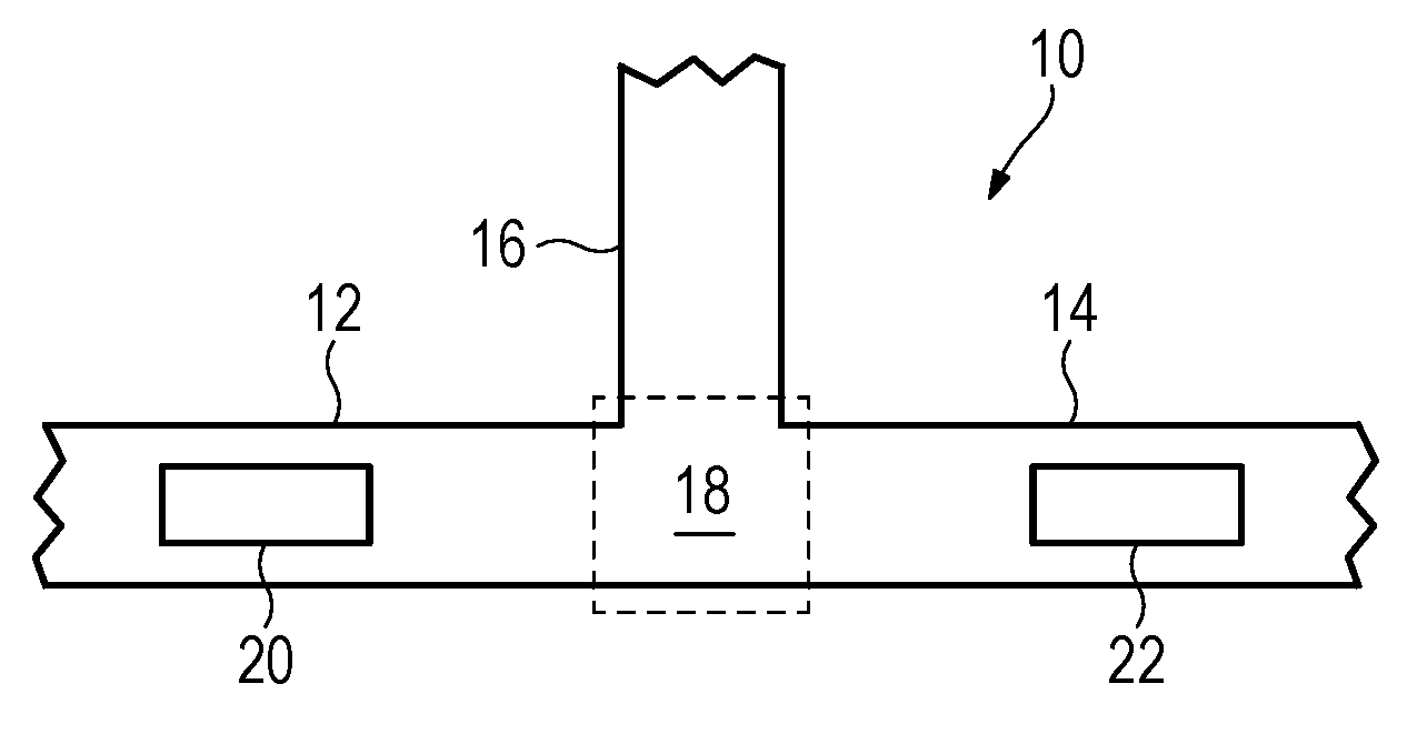
[0003] FIG. 1 provides a diagram of some components of an example microfluidic device.
[0004] FIGS. 2A-G provide diagrams of operation of some components of an example microfluidic device.
[0005] FIGS. 3A-C provide diagrams of some components of example microfluidic devices.
[0006] FIGS. 4A-B provide diagrams of some components of example microfluidic devices.
[0007] FIG. 5 provides a diagram of some components of an example microfluidic device.
[0008] FIGS. 6A-B provide diagrams of some components of example microfluidic devices.
[0009] FIG. 7 provides a diagram of some components of an example microfluidic device.
[0010] FIG. 8 provides a diagram of some components of an example microfluidic device.
[0011] FIGS. 9A-C provide diagrams of some components of example microfluidic devices.
[0012] FIG. 10 provides a block diagram of some components of an example microfluidic device.
[0013] FIG. 11 provides a flowchart that illustrates a sequence of operations that may be performed by an example microfluidic device.
[0014] FIG. 12 provides a flowchart that illustrates a sequence of operations that may be performed by an example microfluidic device.
[0015] FIG. 13 provides a flowchart that illustrates a sequence of operations that may be performed by an example microfluidic device.
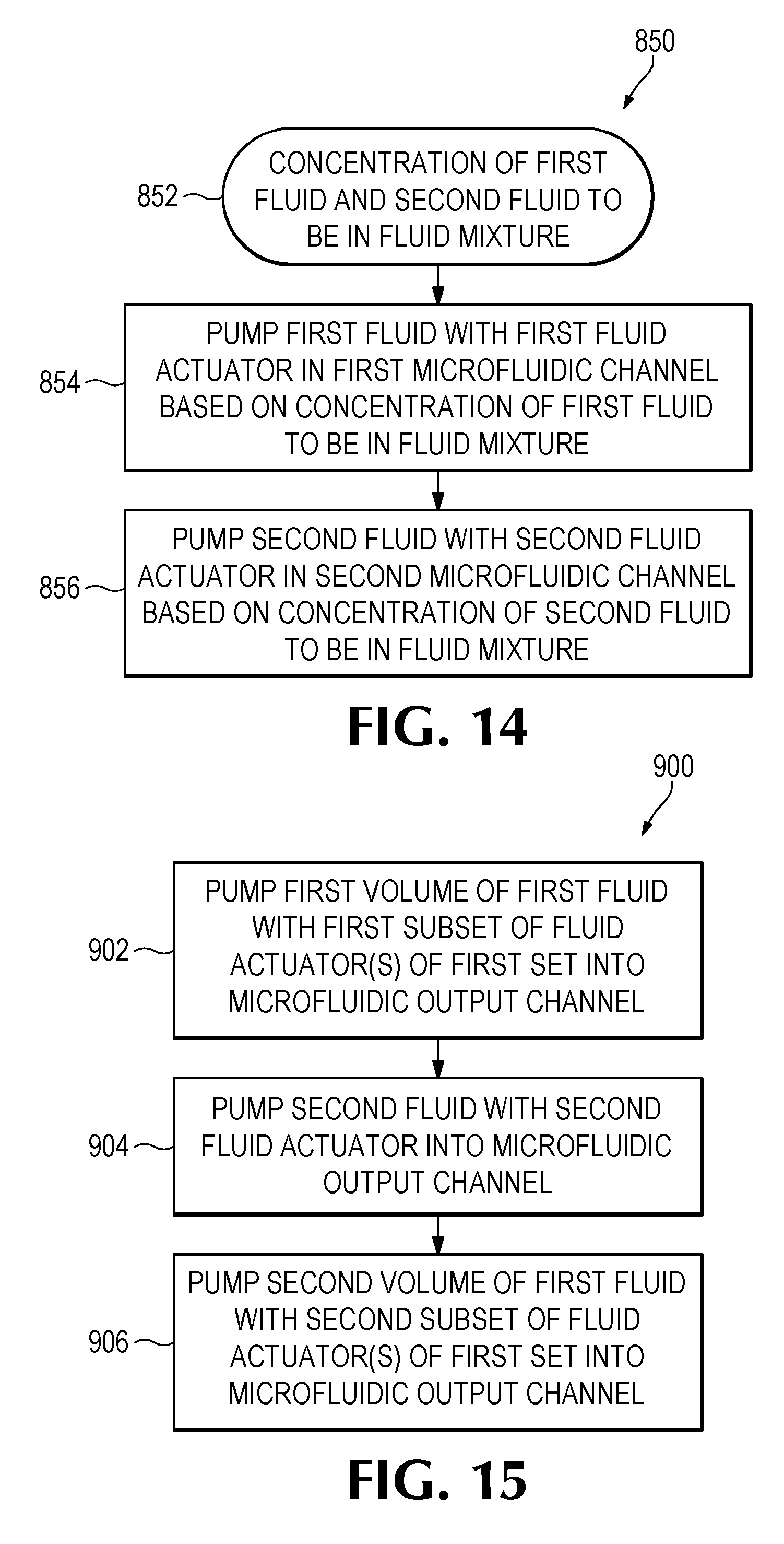
[0016] FIG. 14 provides a flowchart that illustrates a sequence of operations that may be performed by an example microfluidic device.
[0017] FIG. 15 provides a flowchart that illustrates a sequence of operations that may be performed by an example microfluidic device.
[0018] FIG. 16 provides a flowchart that illustrates a sequence of operations that may be performed by an example microfluidic device.
[0019] Throughout the drawings, identical reference numbers designate similar, but not necessarily identical, elements. The figures are not necessarily to scale, and the size of some parts may be exaggerated to more clearly illustrate the example shown. Moreover the drawings provide examples and/or implementations consistent with the description; however, the description is not limited to the examples and/or implementations provided in the drawings.
DESCRIPTION
[0020] Examples provided herein include devices, methods, and processes for microfluidic devices. Some example microfluidic devices include lab-on-a-chip devices (e.g., polymerase chain reaction devices, chemical sensors, etc.), fluid ejection devices (e.g., inkjet printheads, fluid analysis devices, etc.), and/or other such microdevices having microfluidic structures and associated components. Examples described herein may comprise microfluidic channels and fluid actuators disposed therein, where the microfluidic channels may be fluidly coupled together, and the fluid actuators may be actuated to dispense nanoliter and picoliter scale volumes of various fluids.
[0021] Example devices may comprise a first microfluidic channel, a second microfluidic channel, and a microfluidic output channel. The first microfluidic channel and the second microfluidic channel may be fluidly coupled to the microfluidic output channel at a fluid junction. A first fluid actuator may be disposed in the first microfluidic channel, and a second fluid actuator may be disposed in the second microfluidic channel. The first fluid actuator is to actuate to thereby pump a first fluid into the microfluidic output channel, and the second fluid actuator is to actuate to thereby pump a second fluid into the microfluidic output channel. By selectively actuating the first and second fluid actuators, it will be appreciated that a fluid mixture that includes at least the first fluid and the second fluid may be pumped into the microfluidic output channel.
[0022] As will be appreciated, examples provided herein may be formed by performing various microfabrication and/or micromachining processes on a substrate to form and/or connect structures and/or components. The substrate may comprise a silicon based wafer or other such similar materials used for microfabricated devices (e.g., glass, gallium arsenide, plastics, etc.). Examples may comprise microfluidic channels, fluid actuators, and/or volumetric chambers. Microfluidic channels and/or chambers may be formed by performing etching, microfabrication processes (e.g., photolithography), or micromachining processes in a substrate. Accordingly, microfluidic channels and/or chambers may be defined by surfaces fabricated in the substrate of a microfluidic device.
[0023] A fluid actuator, as used herein may correspond to an inertial pump. Fluid actuators that may be implemented as inertial pumps described herein may include, for example, thermal actuators, piezo-membrane based actuators, electrostatic membrane actuators, mechanical/impact driven membrane actuators, magnetostrictive drive actuators, electrochemical actuators, other such microdevices, or any combination thereof. In some examples, fluid actuators may be formed in microfluidic channels by performing various microfabrication processes.
[0024] In some examples, a fluid actuator may correspond to an inertial pump. As used herein, an inertial pump corresponds to a fluid actuator and related components disposed in an asymmetric position in a microfluidic channel, where an asymmetric position of the fluid actuator corresponds to the fluid actuator being positioned less distance from a first end of a microfluidic channel as compared to a distance to a second end of the microfluidic channel. Accordingly, in some examples, a fluid actuator of an inertial pump is not positioned at a mid-point of a microfluidic channel. The asymmetric positioning of the fluid actuator in the microfluidic channel facilitates an asymmetric response in fluid proximate the fluid actuator that results in fluid displacement when the fluid actuator is actuated. Repeated actuation of the fluid actuator causes a pulse-like flow of fluid through the microfluidic channel.
[0025] In some examples, an inertial pump includes a thermal actuator having a heating element (e.g., a thermal resistor) that may be heated to cause a bubble to form in a fluid proximate the heating element. In such examples, a surface of a heating element (having a surface area) may be proximate to a surface of a microfluidic channel in which the heating element is disposed such that fluid in the microfluidic channel may thermally interact with the heating element. In some examples, the heating element may comprise a thermal resistor with at least one passivation layer disposed on a heating surface such that fluid to be heated may contact a topmost surface of the at least one passivation layer. Formation and subsequent collapse of such bubble may generate circulation flow of the fluid. As will be appreciated, asymmetries of the expansion-collapse cycle for a bubble may generate such flow for fluid pumping, where such pumping may be referred to as "inertial pumping." In other examples, a fluid actuator corresponding to an inertial pump may comprise a membrane (such as a piezo-electric membrane) that may generate compressive and tensile fluid displacements to thereby cause fluid flow.
[0026] As will be appreciated, a fluid actuator may be connected to a controller, and electrical actuation of a fluid actuator (such as a fluid actuator of an inertial pump) by the controller may thereby control pumping of fluid. Actuation of a fluid actuator may be of relatively short duration. In some examples, the fluid actuator may be pulsed at a particular frequency for a particular duration. In some examples, actuation of the fluid actuator may be 1 microsecond (.mu.s) or less. In some examples, actuation of the fluid actuator may be within a range of approximately 0.1 microsecond (.mu.s) to approximately 10 milliseconds (ms). In some examples described herein, actuation of a fluid actuator comprises electrical actuation. In such examples, a controller may be electrically connected to a fluid actuator such that an electrical signal may be transmitted by the controller to the fluid actuator to thereby actuate the fluid actuator. Each fluid actuator of an example microfluidic device may be actuated according to actuation characteristics. Examples of actuation characteristics include, for example, frequency of actuation, duration of actuation, number of pulses per actuation, intensity or amplitude of actuation, phase offset of actuation. As will be appreciated in some examples, at least one actuation characteristic may be different for each fluid actuator. For example, a first fluid actuator may be actuated according to first actuation characteristics and a second fluid actuator may be actuated according to second actuation characteristics, where the actuation characteristics for a respective fluid actuator may be based at least in part on a desired concentration of a respective fluid in a fluid mixture, a fluid characteristic of the respective fluid, a fluid actuator characteristic, and/or other such characteristics or input/output variables. For example, the first fluid actuator may be actuated a first number of times and the second fluid actuator may be actuated a second number of times such that a desired concentration of a first fluid and a desired concentration of a second fluid are present in a fluid mixture.
[0027] In some examples described herein, at least one dimension of a microfluidic channel and/or capillary chamber may be of sufficiently small size (e.g., of nanometer sized scale, micrometer sized scale, millimeter sized scale, etc.) to facilitate pumping of small volumes of fluid (e.g., picoliter scale, nanoliter scale, microliter scale, milliliter scale, etc.). For example, some microfluidic channels may facilitate capillary pumping due to capillary force. In addition, examples may couple at least two microfluidic channels to a microfluidic output channel via a fluid junction. At least one fluid actuator may be disposed in each of the at least two microfluidic channels, and the fluid actuators may be selectively actuated to thereby pump fluid into the microfluidic output channel.
[0028] The microfluidic channels may facilitate conveyance of different fluids (e.g., liquids having different chemical compounds, different concentrations, etc.) to the microfluidic output channel. In some examples, fluids may have at least one different fluid characteristic, such as vapor pressure, temperature, viscosity, density, contact angle on channel walls, surface tension, and/or heat of vaporization. It will be appreciated that examples disclosed herein may facilitate mixing of miscible fluids. Furthermore it will be appreciated that examples disclosed herein may facilitate manipulation of small volumes of liquids.
[0029] The fluid actuators of each microfluidic channel may be selectively actuated to pump the different fluids into the microfluidic output channel to thereby create a mixture of the different fluids in the microfluidic output channel, where the mixture may have desired concentrations of each different fluid. Therefore, it will be appreciated that examples disclosed herein may facilitate small volume (e.g., picoliter scale, nanoliter scale, microliter scale, milliliter scale, etc.) mixing of at least two fluids at various ratios/concentrations. In some examples, a fluid mixture of a microfluidic output channel may include a first fluid at a first concentration and a second fluid at a second concentration. As will be appreciated, fluid actuators may be correspondingly actuated in some examples to achieve the desired fluid concentrations for the fluid mixture. In some examples, the at least one fluid actuator of each microfluidic channel may be actuated alternatively such that fluid from each respective channel may be pumped into the microfluidic output channel alternatively. In some examples, such pumping by actuation of fluid actuators may be referred to as asynchronous actuation, where asynchronous actuation describes that the fluid actuators may be actuated alternatively, out-of-phase, not at the same time, etc.
[0030] Turning now to the figures, and particularly to FIG. 1, this figure provides a diagram that illustrates some components of an example microfluidic device 10. In this example, the microfluidic device 10 comprises a first microfluidic channel 12, a second microfluidic channel 14, and a microfluidic output channel 16. As shown, the first microfluidic channel 12 and the second microfluidic channel 14 are fluidly coupled to the microfluidic output channel 16 at a fluid junction 18. As shown, the device 10 comprises a first fluid actuator 20 disposed in the first microfluidic channel 12, and the device 10 comprises a second fluid actuator 22 disposed in the second microfluidic channel 14.
[0031] In examples similar to the example of FIG. 1, the first microfluidic channel may facilitate conveyance of a first fluid from a first source (e.g., a fluid reservoir, a fluid input, etc.), and the second microfluidic channel 14 may facilitate conveyance of a second fluid from a second source (e.g., a fluid reservoir, a fluid input, etc.). The fluid actuators 20, 22 may be actuated to thereby pump the first fluid and/or the second fluid towards the fluid junction 18 and into the microfluidic output channel 16. As will be appreciated, by alternatively actuating the first fluid actuator 20 and the second fluid actuator 22, examples may selectively pump the first fluid and the second fluid into the microfluidic output channel in discrete volumes. As will be appreciated, actuation of the first fluid actuator 20 and the second fluid actuator 22 may be based at least in part on a desired ratio of the first fluid and the second fluid in the microfluidic output channel. In addition, it may be appreciated that characteristics of actuation of the first fluid actuator 20 and the second fluid actuator 22 may correspond to a volume and/or flow rate of the first fluid or the second fluid pumped into the microfluidic output channel 16. Examples of characteristics of actuation that may be varied to thereby control a volume, a flow rate, and/or a concentration of a fluid pumped into the microfluidic output channel include a frequency of actuation, a duration (e.g., pulse width) of actuation, timing offset (e.g., phase offset) of actuation, number of pulses for actuation, intensity/amplitude of actuation, and/or other such characteristics of actuation.
[0032] For example, if a ratio of a fluid mixture for the microfluidic output channel is 2:1 with regard to a first fluid to a second fluid, some examples may actuate a first fluid actuator at a first frequency to pump a first volume of the first fluid into the microfluidic output channel, and a second fluid actuator may be actuated at a second frequency to pump a second volume of the second fluid into the microfluidic output channel such that the first fluid and second fluid in the microfluidic output channel at the ratio of 2:1. As another example, a first fluid actuator may be actuated twice for every one actuation of the second fluid actuator. As another example, a first fluid actuator may be actuated for a longer duration (i.e., with a longer pulse width) as compared to the second fluid actuator. Other examples may perform some combination of such examples to cause a desired ratio of fluids, a desired concentration of fluids, etc. to be pumped into the microfluidic output channel.
[0033] In other examples, it will be appreciated that the fluid actuators 20, 22 may be implemented in inertial pumps. As discussed previously, the fluid actuators 20, 22 are positioned asymmetrically in the microfluidic channels 12, 14. In this example, the fluid actuators 20, 22 are disposed in the microfluidic channels 12, 14 nearer (i.e., less distance) to the fluid junction 18 as compared to the opposite ends of the microfluidic channels 12, 14. Accordingly, the fluid actuators 20, 22 of FIG. 1 may be inertial pumps. In some examples that incorporate inertial pumps, fluid mixing may be facilitated by the alternatively correlated actuation of the inertial pumps disposed on each side of the fluid junction. Therefore, examples including inertial pumps may asynchronously pump fluid with each inertial pump such that the pulse-like flow generated by the inertial pumps causes a fluid mixture to be pumped into the microfluidic output channel.
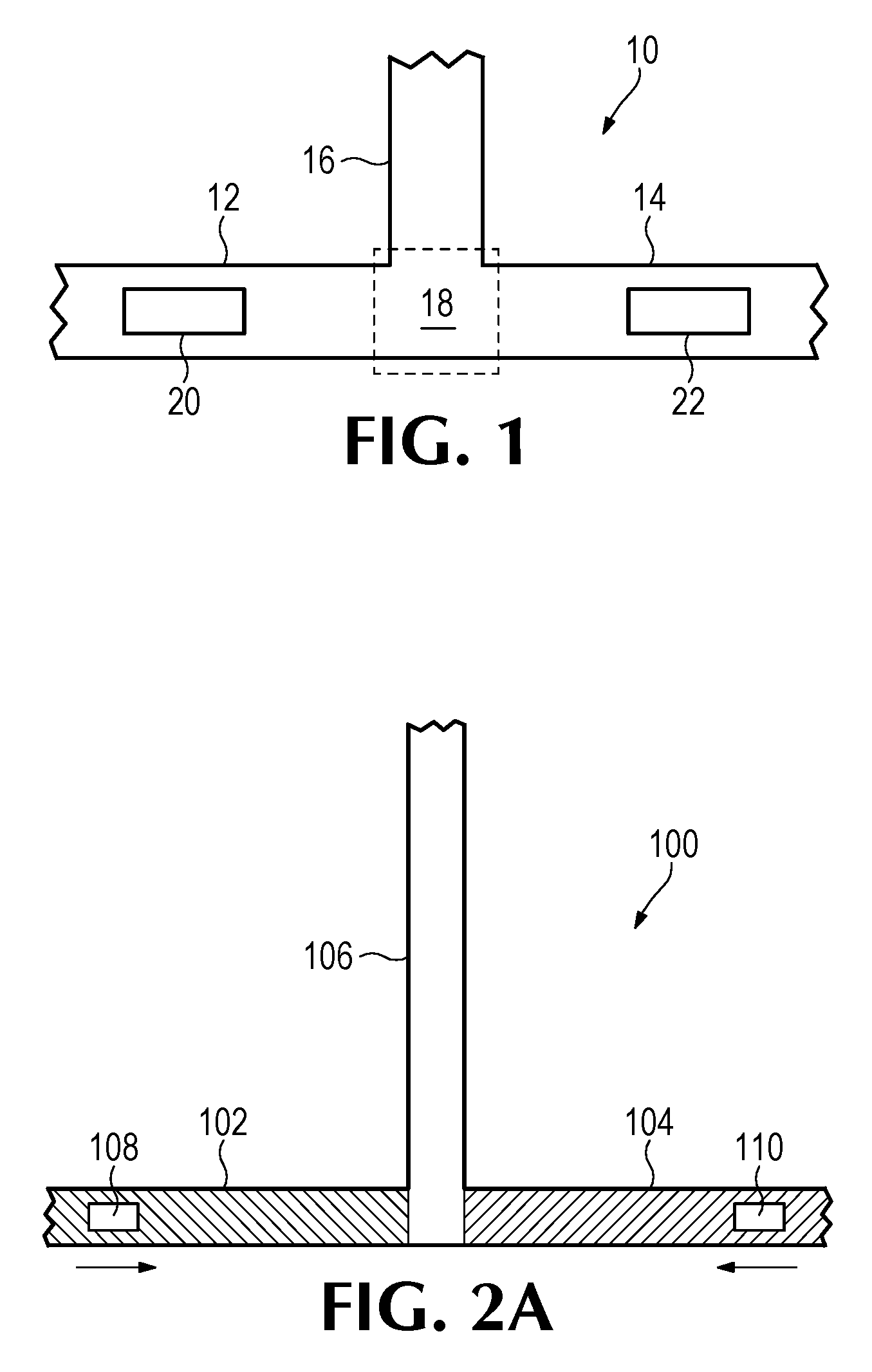
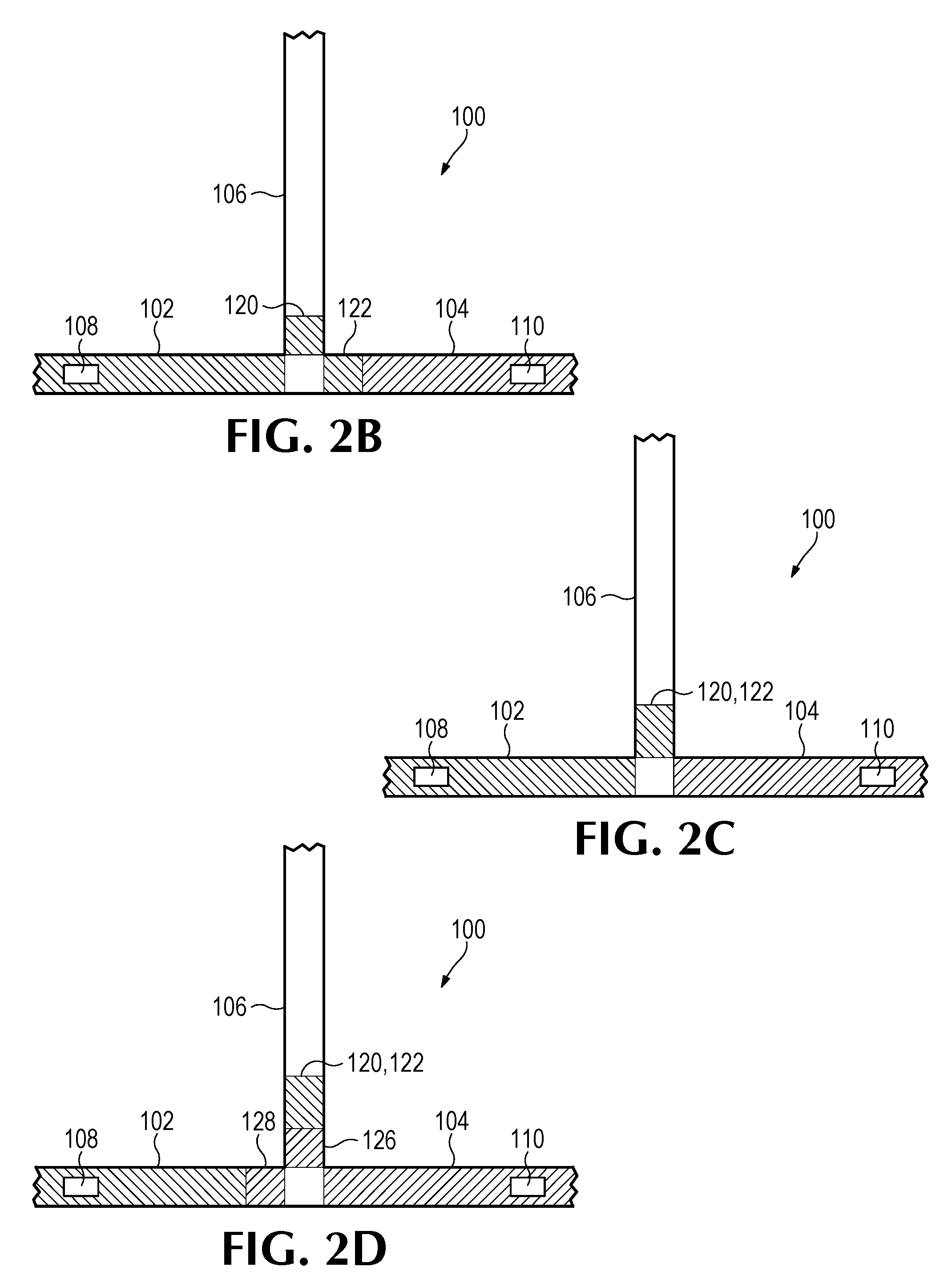
[0034] FIGS. 2A-G illustrate diagrams of operation of an example microfluidic device 100 to pump a mixture of first fluid in a first microfluidic channel 102 and a second fluid in a second microfluidic channel 104 into a microfluidic output channel 106. As shown, the first microfluidic channel 102, second microfluidic channel, and the microfluidic output channel are fluidly coupled at a fluid junction (not labeled). As shown, the microfluidic device 100 includes a first fluid actuator 108 disposed in the first microfluidic channel 102 and a second fluid actuator 110 disposed in the second microfluidic channel 104.
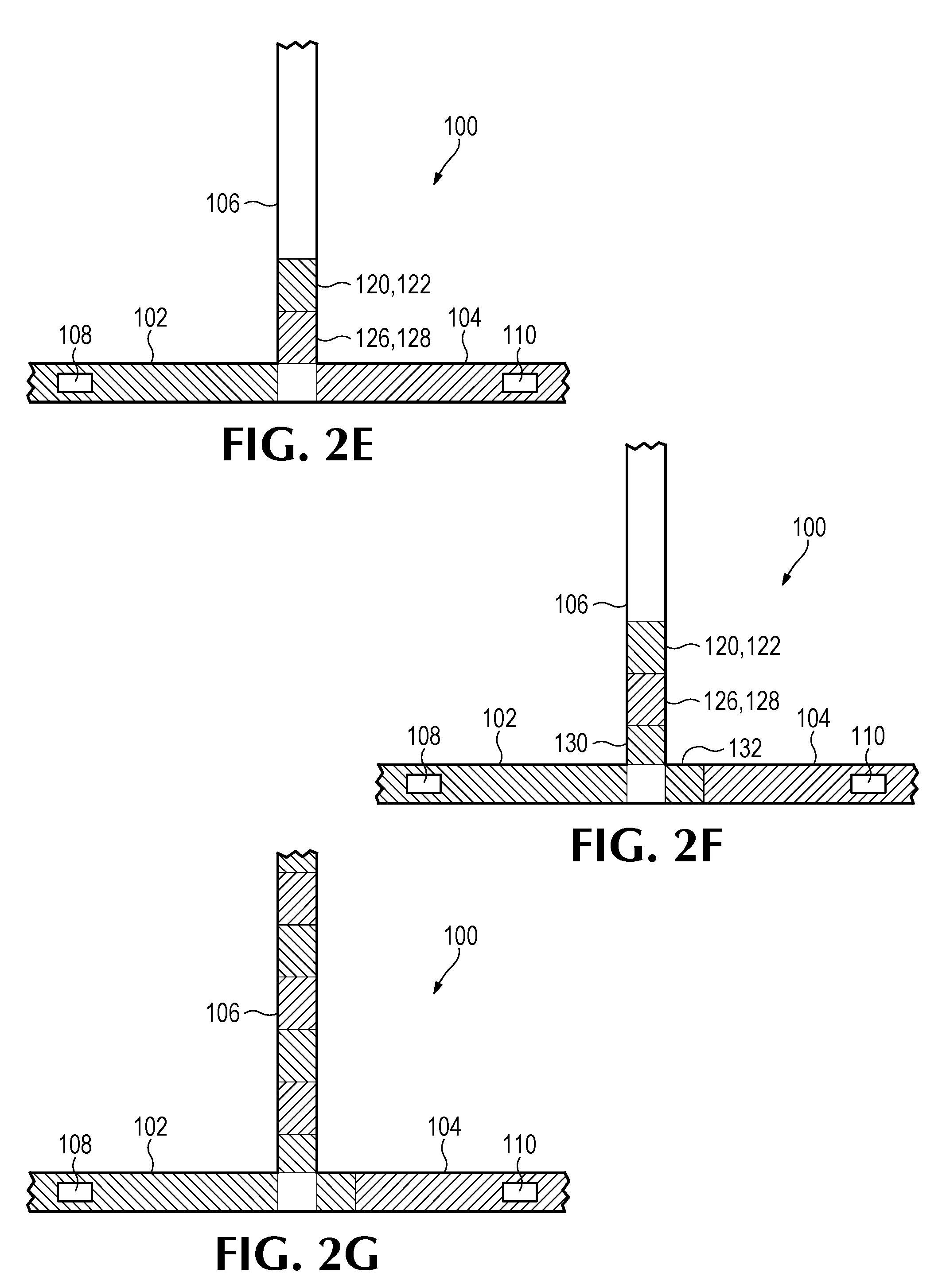
[0035] In FIG. 2A, the device may be at an initial state, in which fluids have not been pumped into the microfluidic output channel 106. In FIG. 2B, the first fluid actuator 108 may be actuated (which may also be referred to as "firing the actuator") two times such that a first respective volume of the first fluid 120 is pumped into microfluidic output channel 106, and it will be noted that a second respective volume of the first fluid is pumped into the second microfluidic channel 104. In FIG. 2C, the second fluid actuator 110 may be actuated such that the second respective volume of the first fluid 122 that was in the second microfluidic channel 104 in FIG. 2B is pumped into the microfluidic output channel 106. In FIG. 2D, the second fluid actuator 110 may be actuated twice such that a first respective volume of the second fluid 126 may be pumped into the microfluidic output channel 106, and a second respective volume of the second fluid 128 may be pumped into the first microfluidic channel 102. In FIG. 2E, the first fluid actuator 108 may be actuated once such that the second respective volume of the second fluid 128 that was in the first microfluidic channel 102 is pumped into the microfluidic output channel 106. In FIG. 2F, the first fluid actuator may be actuated twice to thereby pump a third respective volume of the first fluid 130 into the microfluidic output channel 106, and a fourth respective volume of the first fluid 132 may be pumped into the second microfluidic channel 104. Therefore, in this example, the first fluid actuator 108 and the second fluid actuator 110 may be alternatively actuated to thereby pump respective volumes 120-132 into the microfluidic output channel 106. FIG. 2G illustrates the example operation of the example device 100 where the first fluid actuator 108 and the second fluid actuator 110 have been operated as described with regard to FIGS. 2A-2F to thereby pump a mixture of the first fluid and the second fluid into the microfluidic output channel 106. As will be appreciated, in this example, the ratio of the first fluid to the second fluid pumped into the microfluidic output channel is approximately 1:1. However, other examples may pump at least two fluids into a microfluidic output channel at a various ratios (and therefore concentrations) based on a configuration and/or actuation of fluid actuators implemented therein.
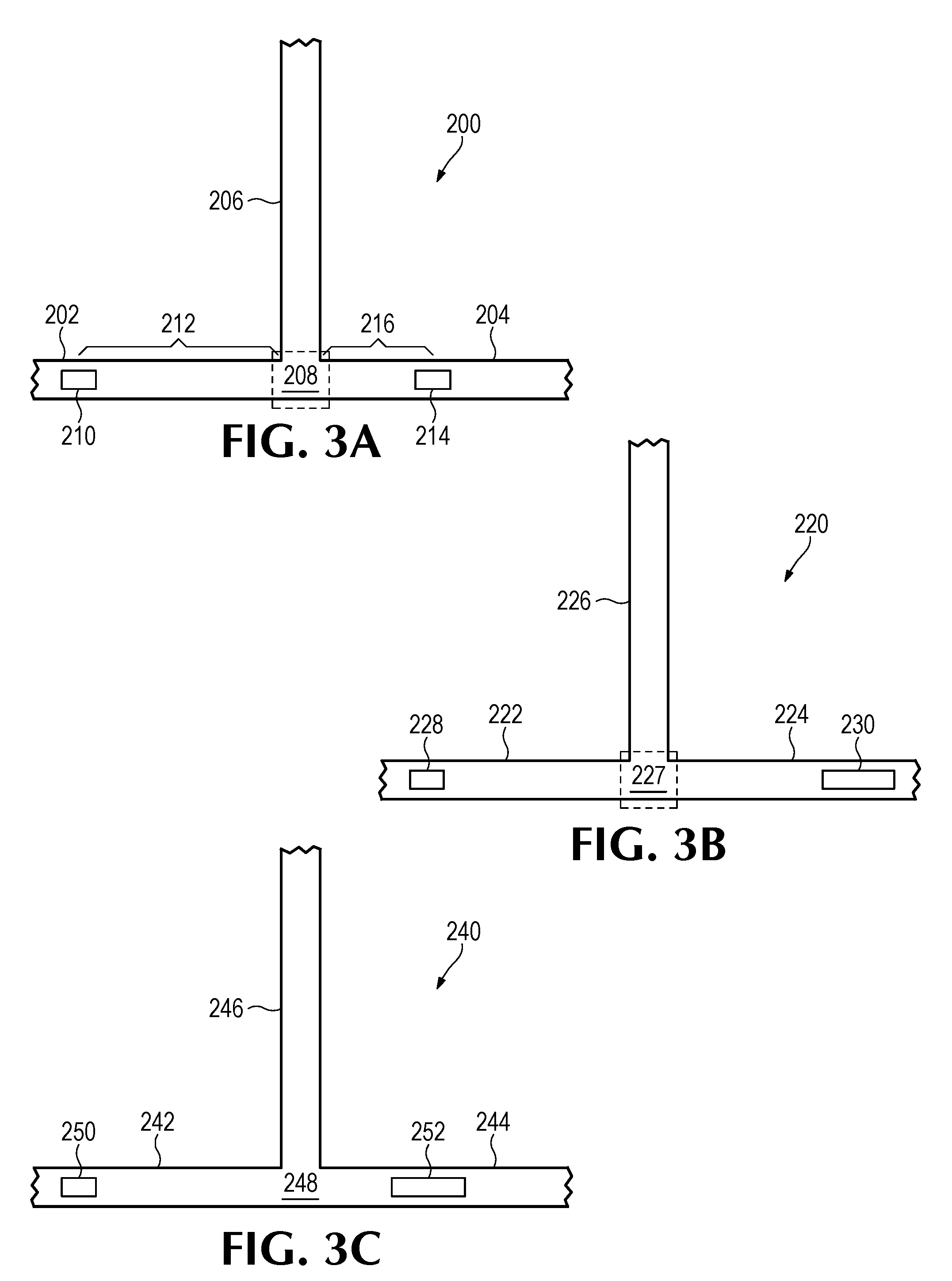
[0036] FIGS. 3A-C provide diagrams that illustrate some components of example microfluidic devices. FIG. 3A illustrates an example microfluidic device 200 comprising a first microfluidic channel 202 and a second microfluidic channel 204 fluidly coupled to a microfluidic output channel 206 at a fluid junction 208. As shown in this example, a first fluid actuator 210 is disposed in the first microfluidic channel 202 a first distance 212 from the fluid junction 208, and a second fluid actuator 214 is disposed in the second microfluidic channel 204 a second distance 216 from the fluid junction 208. In this example, the first distance 212 and the second distance 216 may be different. As will be appreciated, the different distances 212, 216 for the first fluid actuator 210 and the second fluid actuator 214 to the fluid junction 208 may facilitate a different flow rate and/or different volume of fluid that each fluid actuator 210, 214 may pump into the microfluidic output channel 206. As will be appreciated, examples similar to the example of FIG. 3A may be described as having fluid actuators asymmetrically disposed in microfluidic channels.
[0037] FIG. 3B illustrates an example microfluidic device 220 comprising a first microfluidic channel 222 and a second microfluidic channel 224 fluidly coupled to a microfluidic output channel 226 via a fluid junction 227. As shown, the device 220 comprises a first fluid actuator 228 disposed in the first microfluidic channel 222 and a second fluid actuator 230 disposed in the second microfluidic channel 224. In this example, the first fluid actuator 228 is of a first size and the second fluid actuator 230 is of a second size, where the sizes are different. For example, if the fluid actuators 228, 230 are thermal-based fluid actuators, a thermal resistor of the first fluid actuator 228 may be smaller in size (e.g., surface area) as compared to the thermal resistor of the second fluid actuator 230. As another example, if the fluid actuators 228, 230 are piezo-electric based fluid actuators, a piezo-electric membrane of the first fluid actuator 228 may be smaller in size (e.g., surface area) as compared to the piezo-electric membrane of the second fluid actuator. As will be appreciated, a size of the fluid actuators 228, 230 may correspond to a flow rate of fluid and/or volume of fluid that the fluid actuator 228, 230 may pump when actuated. Accordingly, in this example, the microfluidic device may pump a greater volume of a second fluid with the second fluid actuator 230 when actuated as compared to a volume of a first fluid pumped by actuation of the first fluid actuator 228. Examples similar to the example of FIG. 3C may be described as having asymmetric fluid actuators.
[0038] FIG. 3C provides a diagram of some components of an example microfluidic device 240 that comprises a first microfluidic channel 242 and a second microfluidic channel fluidly coupled to a microfluidic output channel 246 via a fluid junction 248. In this example, the device 240 comprises a first fluid actuator 250 disposed a first distance from the fluid junction 248 in the first microfluidic channel 242, and the device 240 comprises a second fluid actuator 252 disposed a second distance from the fluid junction 248 in the second microfluidic channel 244. In addition, the first fluid actuator 250 and the second fluid actuator 252 are of different sizes. As discussed above with regard to FIGS. 3A and 3B, asymmetric positioning of the fluid actuators 250, 252 relative to the fluid junction 248 and asymmetric fluid actuators 250, 252 may correspond to a respective volume of fluid that each fluid actuator may pump into the microfluidic output channel 246. In addition, the asymmetric positioning of the fluid actuators 250, 252 relative to the fluid junction 248 and asymmetric fluid actuators 250, 252 may correspond to a flow rate at which each fluid actuator 250, 252 may pump fluid into the microfluidic output channel 246.
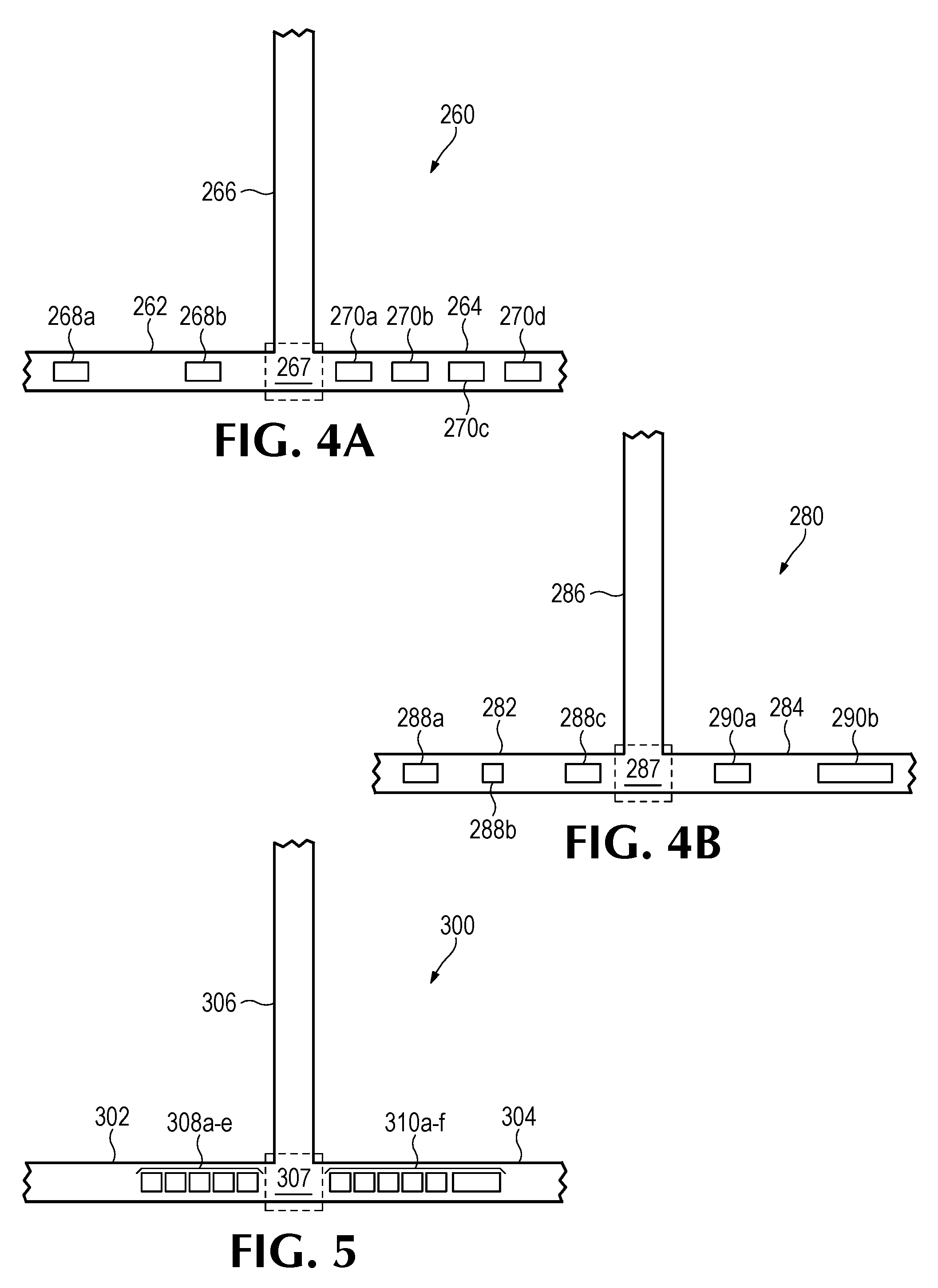
[0039] FIGS. 4A-B provide diagrams of some components of example microfluidic devices. In FIG. 4A, the microfluidic device 260 comprises a first microfluidic channel 262, a second microfluidic channel 264, and a microfluidic output channel 266 fluidly coupled thereto via fluid junction 267, as described in other examples. In this example, the device 260 includes a first set of fluid actuators 268a-b disposed in the first microfluidic channel 262, and the device includes a second set of fluid actuators 270a-d disposed in the second fluid channel 264. For the first set of actuators 268a-b, a first fluid actuator 268a is disposed a second distance away from the fluid junction 267 and a second fluid actuator 268b is disposed a first distance away from the fluid junction 267, where the first distance is less than the second distance. For the second set of fluid actuators 270a-d: a first fluid actuator 270a is disposed a first distance from the fluid junction 267; a second fluid actuator 270b is disposed a second distance from the fluid junction 267; a third fluid actuator 270c is disposed a third distance from the fluid junction 267; and a fourth fluid actuator 270d is disposed a fourth distance from the fluid junction 267. As shown in this example, for the second set of fluid actuators 270a-d: the first distance is less than the second distance; the second distance is less than the third distance; and the third distance is less than the fourth distance. Accordingly, the second set of fluid actuators 270a-d may be described as arranged along a length of the second microfluidic channel 264.
[0040] In examples similar to the examples of FIG. 4A, it will be appreciated that examples may actuate the fluid actuators of the first set 268a-b individually or in combination to thereby facilitate pumping of different volumes of fluid and/or pumping at different flow rates. For example, the first fluid actuator 268a of the first set 268a-b may be actuated to thereby pump a first volume of a first fluid into the microfluidic output channel 266. The second fluid actuator 268b of the first set 268a-b may be actuated to thereby pump a second volume of the first fluid into the microfluidic output channel 266. Both fluid actuators of the first set 268a-b may be actuated concurrently (e.g., at the same time and/or within in a short time-span) to thereby pump a third volume of the first fluid into the microfluidic output channel 266. Similarly, examples may actuate the fluid actuators of the second set 270a-d individually and/or in combinations to thereby pump different volumes of a second fluid into the microfluidic output channel 266.
[0041] FIG. 4B provides a diagram that illustrates some examples of a microfluidic device 280 that comprises a first microfluidic channel 282, a second microfluidic channel 284, and a microfluidic output channel 286 fluidly coupled thereto via a fluid junction 287, as described in other examples. In this example, the microfluidic device 280 comprises a first set of fluid actuators 288a-c disposed in the first microfluidic channel 282 and along a length of the first microfluidic channel 282. In this example, similar to the example of FIG. 3B, a first fluid actuator 288a, a second fluid actuator 288b, and a third fluid actuator of the first set 288a-c are of different sizes. Therefore, in this example, actuation of each fluid actuator of the first set 288a-c may pump a different volume of a first fluid from the first microfluidic channel 282 into the microfluidic output channel 286. In addition, similar to the example of FIG. 3A, the distance of each fluid actuator of the first set 288a-c may also correspond to a flow rate of fluid and/or volume of fluid pumped due to actuation. Furthermore, the device 280 comprises a second set of fluid actuators 290a-b of different sizes disposed in the second microfluidic channel 284, where each fluid actuator of the second set 290a-b is a different distance from the fluid junction 287.
[0042] Accordingly, as illustrated in the examples of FIGS. 4A-B, some example microfluidic devices may comprise a set of fluid actuators disposed in and along a length of a microfluidic channel. As will be appreciated a size of a respective fluid actuator as well as a distance of a respective fluid actuator from the fluid junction may be based at least in part on a volume of respective fluid to be pumped, a flow rate of pumping for the respective fluid, a ratio of the respective fluid and all other fluids to be pumped into the microfluidic output channel, and/or a concentration of the respective fluid and all other fluids to be pumped into the microfluidic output channel. As will be appreciated, actuation of the fluid actuators of each set of fluid actuators 288a-c, 290a-b may be selective based on a volume of fluid to be pumped to the microfluidic output channel, a ratio of a respective fluid to be in a fluid mixture in the microfluidic output channel, a concentration of each fluid to be in the fluid mixture, etc. Moreover, in examples described herein, a single fluid actuator of a set may be actuated or a combination of at least two fluid actuators of a set may be actuated in a corresponding manner (e.g., concurrently, synchronously, alternatively, etc.) such that pumping may occur at different flow rates and/or different volumes of fluid may be pumped.
[0043] FIG. 5 is a diagram that illustrates some components of an example microfluidic device 300. In this example, the microfluidic device 300 comprises a first microfluidic channel 302, a second microfluidic channel 304, and a microfluidic output channel 306 fluidly coupled thereto via a fluid junction 307, as described in other examples. In this example, the device 300 comprises a first set of fluid actuators 308a-e disposed in the first microfluidic channel 302 and a second set of fluid actuators 310a-f disposed in the second microfluidic channel 304. In this example, the fluid actuators of each set 308a-e, 310a-f are arranged adjacent to each other along a length of the respective microfluidic channel 302, 304.
[0044] In examples similar to the example of FIG. 5, the adjacently-arranged fluid actuators of a set may be described as a fluid actuator array. In such examples, each fluid actuator of an array may be actuated separately to cause a respective volume of fluid to be pumped at a respective flow rate. Adjacent fluid actuators (e.g., a first fluid actuator 308a and a second fluid actuator 308b) may be actuated concurrently such that the adjacent fluid actuators operate as a single fluid actuator that causes a larger volume of fluid to be pumped into the microfluidic output channel 306 at a higher flow rate as compared to operation of the adjacent fluid actuators separately.
[0045] For example, if the fluid actuators of the first set 308a-e correspond to thermal based fluid actuators, each fluid actuator may comprise a thermal resistor of a particular surface area. By actuating two of the fluid actuators concurrently, the two fluid actuators may operate in a manner similar to a single fluid actuator having the total surface area of the two fluid actuators (e.g., double the particular surface area). As will be appreciated, examples may selectively actuate: a single fluid actuator of the first set 308a-e; at least two fluid actuators of the first set 308a-e; or all fluid actuators of the first set 308a-e to thereby pump different volumes of fluid at different flow rates into the microfluidic output channel 306. The fluid actuators of the second set 310a-f may be operated similarly. In the example of FIG. 5, it will be noted that the second set of fluid actuators 310a-f comprises at least one fluid actuator 310f that is a different size than other fluid actuators of the second set 310a-e. As discussed in previous examples, size of a fluid actuator as well as position (e.g., distance from the fluid junction) may correspond to a volume of fluid to be pumped and/or a rate of flow of pumped fluid.
[0046] As will be appreciated, microfluidic devices may be configured for a particular application (i.e., application specific) such that a characteristics of a microfluidic device may be based at least in part on a desired mixing ratio, a desired concentration, a desired flow rate, and/or other such factors. Example characteristics of some example microfluidic devices include, for example, characteristics of fluid actuators, such as size of fluid actuators, positioning of fluid actuators in microfluidic channels, number of fluid actuators in a respective channel, etc. Further example characteristics of a microfluidic device that may vary based on application include characteristics of the microfluidic channels implemented therein. Example microfluidic channel characteristics include microfluidic channel width, microfluidic channel cross-sectional area, microfluidic channel geometry (e.g., cross-sectional shape), microfluidic channel length, channel texture/surface roughness, etc.
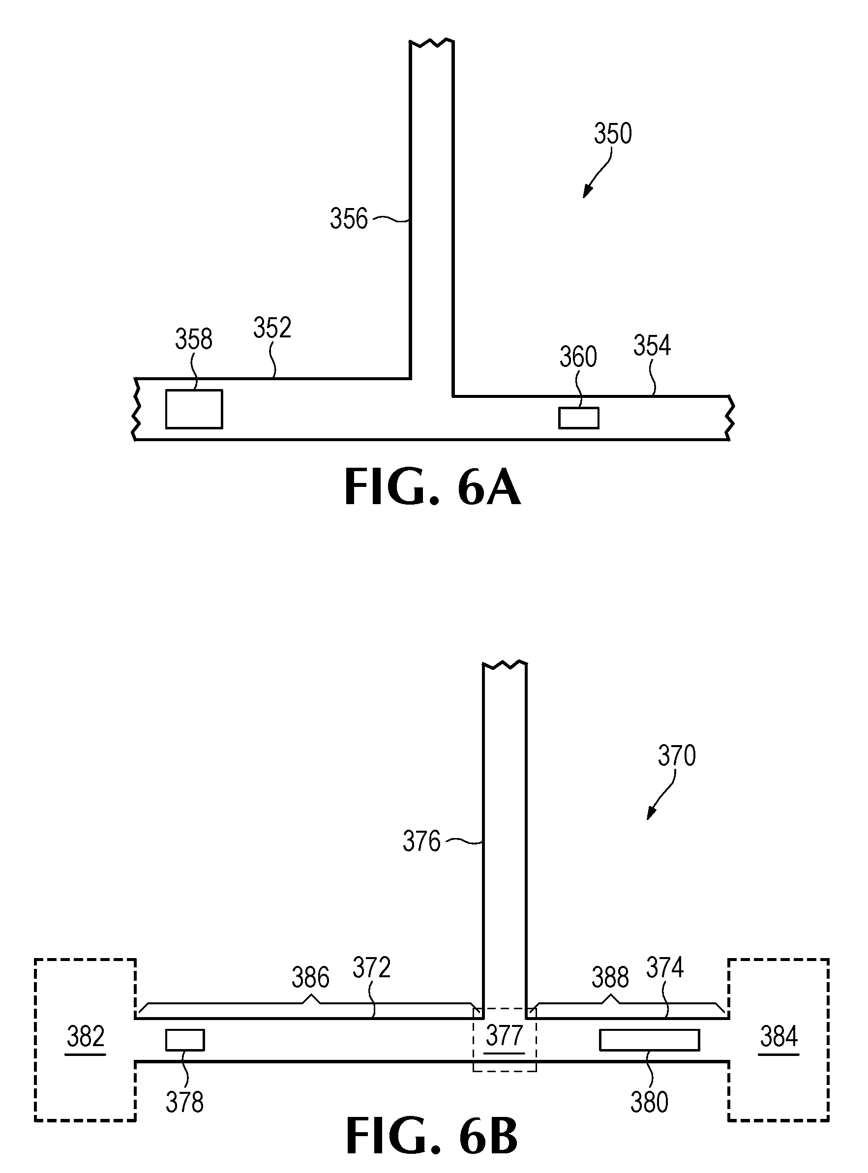
[0047] FIG. 6A is a diagram of an example microfluidic device 350 that includes a first microfluidic channel 352, a second microfluidic channel 354, and a microfluidic output channel 356 fluidly coupled thereto via a fluid junction. In this example, a first fluid actuator 358 is disposed in the first microfluidic channel 352, and a second fluid actuator 360 is disposed in the second microfluidic channel 354. In this example, the first microfluidic channel 352 has a channel width that is greater than a microfluidic channel width of the second microfluidic channel 354. Accordingly, a first volume of a first fluid pumped from the first microfluidic channel 352 into microfluidic output channel 356 may be greater than a second volume of a second fluid pumped from the second microfluidic channel 354 into the microfluidic output channel 356. Therefore, in some examples, a microfluidic channel width may be based at least in part on a desired ratio of the first fluid to the second fluid in a fluid mixture in the microfluidic output channel 356.
[0048] FIG. 6B is a diagram of an example microfluidic device 370 that comprises a first microfluidic channel 372, a second microfluidic channel 374, and a microfluidic output channel 376 fluidly coupled thereto via a fluid junction 377. The device further comprises a first fluid actuator 378 disposed in the first microfluidic channel 372 and a second fluid actuator 380 disposed in the second microfluidic channel 374. As discussed in previous examples, the microfluidic channels 372, 374 may be connected to fluid reservoirs, fluid inputs, other fluid junctions, etc. In this example, the first microfluidic channel 372 is illustrated as fluidly connected to a first fluid input to input a first fluid, and the second microfluidic channel 374 is fluidly connected to a second fluid input 384 to input a second fluid. In this example, a channel length 386 of the first microfluidic channel 372 is greater than a channel length 388 of the second microfluidic channel 374.
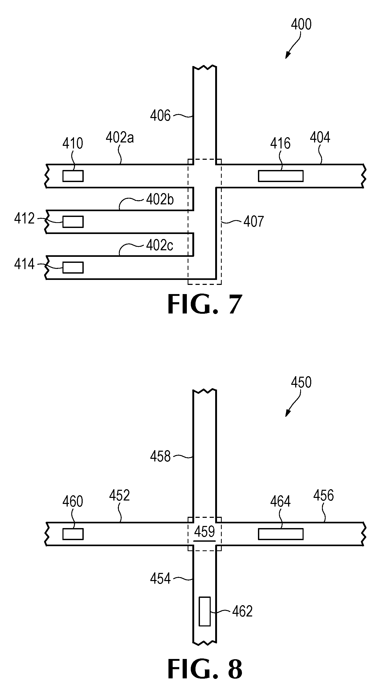
[0049] While the examples illustrated in FIGS. 1-6B illustrate microfluidic devices comprising two microfluidic channels, it will be appreciated that other examples may comprise more than two microfluidic channels. For example, referring to FIG. 7, this figure provides a diagram of an example microfluidic device 400 that includes a first set of microfluidic channels 402a-c, a second microfluidic channel 404, and a microfluidic output channel 406 that is fluidly coupled to the first set of microfluidic channels 402a-c and the second microfluidic channel 404 via a fluid junction 407. The device 400 includes a fluid actuator 408-414 disposed in each microfluidic channel 402a-c, 404. In this example, the first set of microfluidic channels 402a-c may convey a first fluid and the second microfluidic channel 404 may convey a second fluid. Accordingly, in this example, the first fluid may be pumped into the microfluidic output channel in varying volumes based at least in part on the actuation of the fluid actuators 410-414 disposed in the first set of microfluidic channels 402a-c.
[0050] FIG. 8 provides a diagram of some components of an example microfluidic device 450 that comprises a first microfluidic channel 452, a second microfluidic channel 454, a third microfluidic channel 456, and a microfluidic output channel 458 fluidly coupled to the first microfluidic channel 452, the second microfluidic channel 454, and the third microfluidic channel 456 via a fluid junction 459. The device 450 includes a fluid actuator 460-464 disposed in each microfluidic channel 452-456. Accordingly, in this example, the first microfluidic channel 452 may convey a first fluid; the second microfluidic channel 454 may convey a second fluid; and the third microfluidic channel 456 may convey a third fluid. Therefore, in this example, the microfluidic device may selectively actuate the microfluidic actuators 460-464 of the microfluidic channels 452-456 to thereby pump a fluid mixture of the first fluid, second fluid, and third fluid into the microfluidic output channel 458.
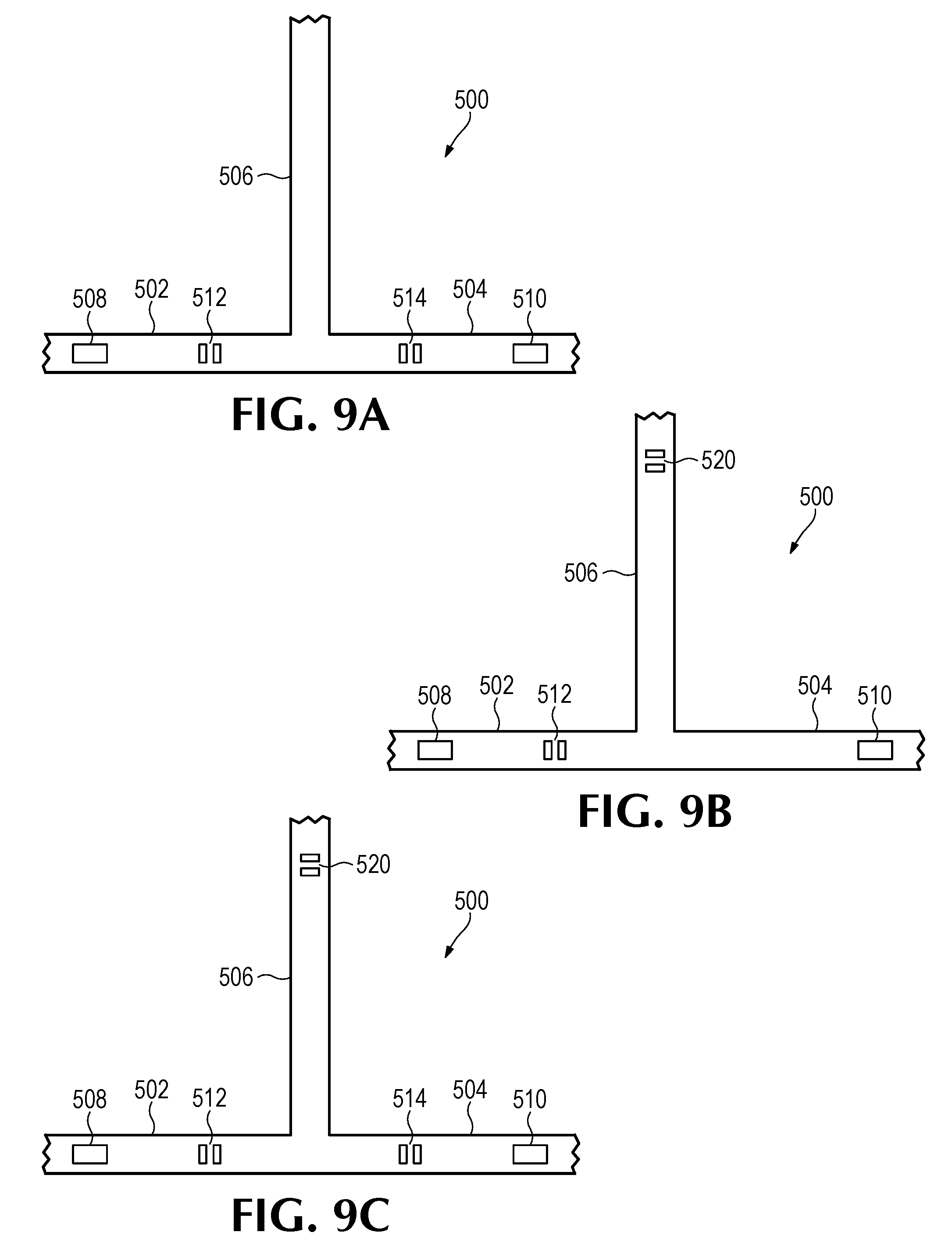
[0051] FIGS. 9A-C provide diagrams of some components of an example microfluidic device 500. The example microfluidic device 500 comprises a first microfluidic channel 502, a second microfluidic channel 504, and a microfluidic output channel fluidly coupled thereto via a fluid junction. Furthermore, the device 500 includes a fluid actuator 508-510 disposed in each microfluidic channel 502-504. In the example of FIG. 9A, the device 500 includes a first fluid sensor 512 disposed in the first microfluidic channel 502, and the device 500 includes a second fluid sensor 514 disposed in the second fluid channel 504. In some examples, the flow sensors 512, 514 may be utilized to detect a flow rate for pumping of a first fluid from the first microfluidic channel 512 or a second fluid second microfluidic channel 504. Accordingly, it will be appreciated that, based on the detected flow rates, a concentration of the first fluid and the second fluid, a mixing ratio of the first fluid and second fluid, and/or a volume of the first fluid and second fluid may be determined for a fluid mixture in the microfluidic output channel 506. In FIG. 9B, the microfluidic device 500 comprises a fluid sensor 520 disposed in the microfluidic output channel 506. Accordingly, in the example of FIG. 9B, a flow rate may be determined for a fluid mixture in the microfluidic output channel 506. In FIG. 9C, the example device 500 comprises fluid sensors 512, 514, 520 disposed in the first microfluidic channel 502, the second microfluidic channel 504, and the microfluidic output channel 506. In the examples shown in FIGS. 9A-C, the fluid sensors 512, 514 of the microfluidic channels 502, 504 is disposed between the fluid actuator 508, 510 and the fluid junction. As will be appreciated, other examples may include fluid sensors disposed at various positions in the microfluidic channels and/or microfluidic output channel.
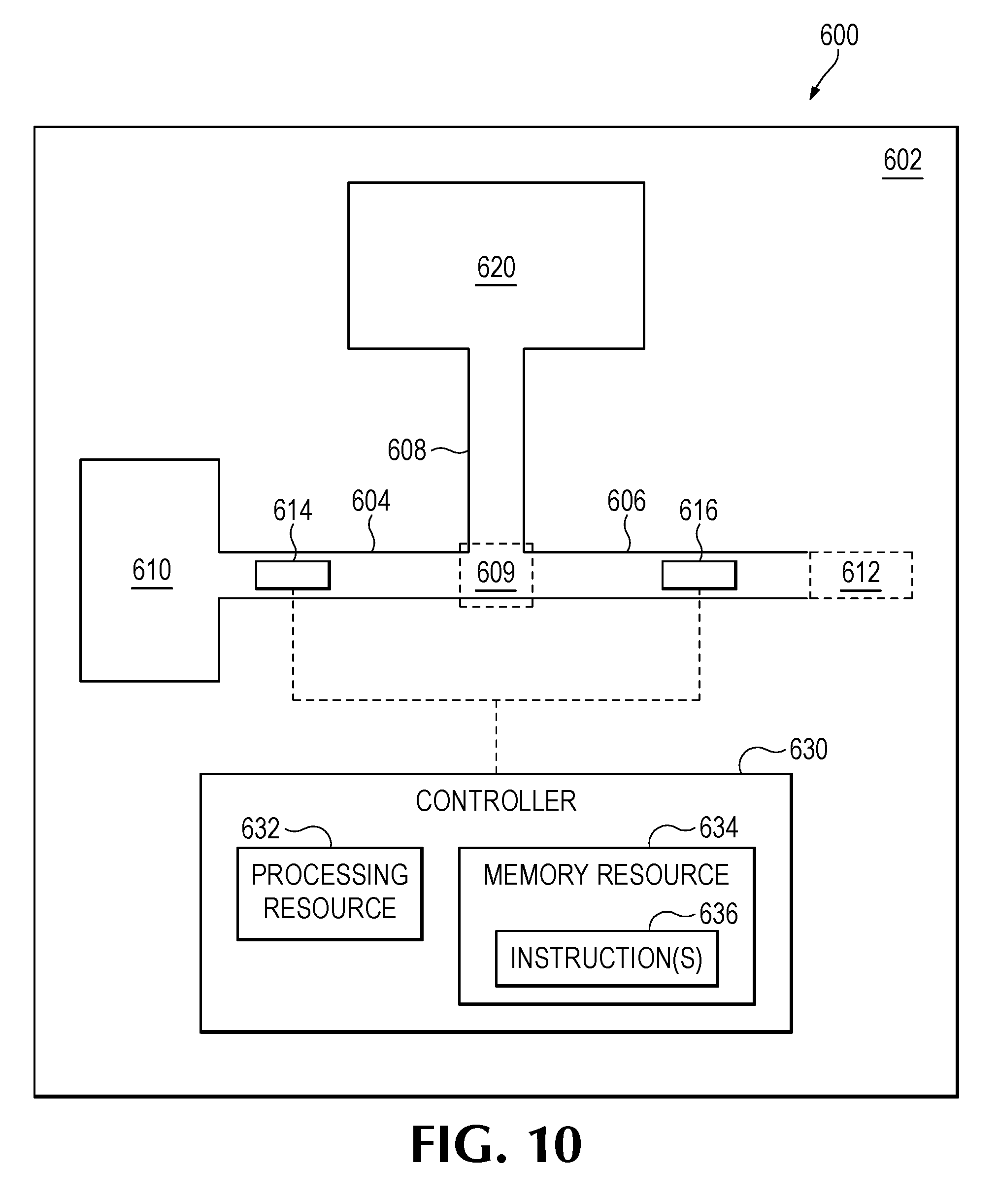
[0052] FIG. 10 provides a block diagram that illustrates some components of an example microfluidic device 600. As discussed previously, various structures/components (e.g., microfluidic channels, capillary chambers, fluid inputs, fluid reservoirs, etc.) may be formed/microfabricated in a substrate (e.g., a silicon wafer portion, a glass wafer portion, etc.). In this example, the device 600 comprises a substrate 602 into which a first microfluidic channel 604 and a second microfluidic channel 606 are formed. In addition, the device 600 includes a microfluidic output channel 608 formed in the substrate 602 that is fluidly connected to the first microfluidic channel 604 and the second microfluidic channel 606 via a fluid junction 609.
[0053] In this example, the first microfluidic channel 604 is fluidly connected to a fluid input 610 (which, in the example, is illustrated as a fluid reservoir) to input a first fluid that may be conveyed to the microfluidic output channel 608 via the first microfluidic channel 604. The second microfluidic channel 606 may be fluidly connected to a fluid input 612 to input a second fluid that may be conveyed to the microfluidic output channel 608 via the second microfluidic channel 606. While the example device 600 is illustrated with a fluid reservoir 610 and a fluid input 612, it will be appreciated that in other examples, the microfluidic channels may be connected to other fluid sources, such as fluid reservoirs, fluid inputs, microfluidic reaction chambers, fluid junctions, etc. The microfluidic device 600 includes a first fluid actuator 614 disposed in the first microfluidic channel 604, and the device includes a second fluid actuator 616 disposed in the second microfluidic channel 606. Furthermore, the microfluidic output channel 608 may be fluidly connected to a microfluidic chamber 620, and the microfluidic chamber 620 may store the fluid mixture. While not shown in this example, the microfluidic chamber 620 may comprise various other components and/or structures, such as fluid ejectors and nozzles, heating elements, fluid analysis sensors, optical detectors, microfluidic columns, and/or other such components that may facilitate further processing and/or analysis of a fluid mixture conveyed to the microfluidic chamber 620 from the microfluidic output channel 608. Therefore, it will be appreciated that the microfluidic chamber 620 may correspond to a microfluidic reaction chamber, an ejection chamber, a chromatography column, an optical detection chamber, or any combination thereof.
[0054] In this example, the fluid actuators 614, 616 may be electrically connected to a controller 630. While not shown other components, such as fluid sensors, optical detectors, fluid ejectors, etc. may be electrically connected to the controller 630. Accordingly, the controller may electrically actuate these components, and the controller may receive data in the form of electrical signals from these components. For example, the controller 630 may electrically actuate fluid actuators 614, 616 to thereby cause the fluid actuators 614, 616 to pump fluid. As another example, the controller may receive sensor data from the fluid sensors that corresponds to a flow rate of a fluid.
[0055] While the term "controller" may be used herein, it will be appreciated that a controller may comprise various types of data processing resources. A controller may include, for example, at least one hardware based processor. Similarly, a controller may comprise one or more general purpose data processors and/or one or more specialized data processors. For example, a controller may comprise a central processing unit (CPU), an application-specific integrated circuit (ASIC), and/or other such configurations of logical components for data processing.
[0056] In some examples, such as the example of FIG. 10, the controller 630 comprises a processing resource 632 and a memory resource 634 that stores executable instructions 636. Execution of instructions 636 may cause the controller and/or device to perform functionalities, processes, and/or sequences of operations described herein. Furthermore, in the examples, the memory resource may comprise a machine-readable storage medium, which may be referred to as a memory. The memory resource may represent random access memory (RAM) devices as well as other types of memory (e.g. cache memories, non-volatile memory devices, read-only memories, etc.). A memory resource may include RAM, ROM, erasable programmable read-only memory (EPROM), electrically erasable programmable read-only memory, flash memory or other solid state memory technology, or any other medium that may be used to store executable instructions and information. Furthermore, the memory resource 636 may be non-transitory.
[0057] In some examples, the controller may be externally located (e.g., in a data processing system) and may be electrically connected to components of an example microfluidic device via electrical connections and conductive traces of the microfluidic device. In other examples, the microfluidic device may comprise a controller disposed on a common substrate and electrically connected to components of the microfluidic device via conductive traces.
[0058] FIGS. 11-16 provide flowcharts that provide example sequences of operations that may be performed by an example microfluidic device and/or a controller thereof to perform example processes and methods. In some examples, the operations included in the flowcharts may be embodied in a memory resource (such as the example memory resource 634 of FIG. 10) in the form of instructions that may be executable by a processing resource to cause the device and/or controller to perform the operations corresponding to the instructions.
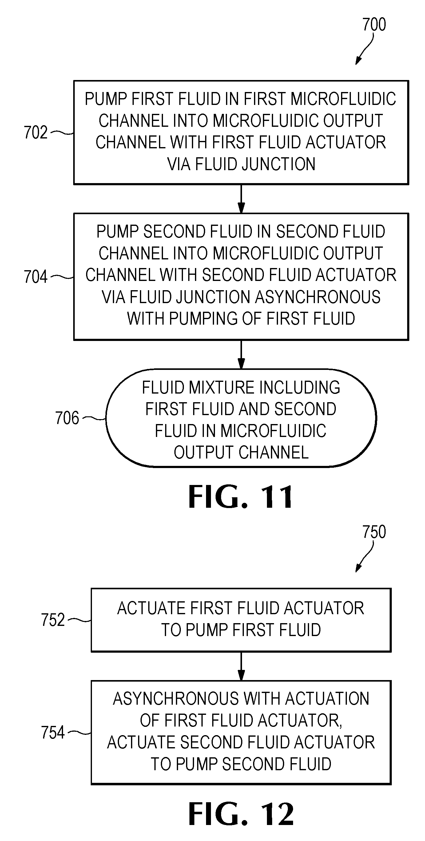
[0059] As shown in FIG. 11, an example device may pump a first fluid in a first microfluidic channel into a microfluidic output channel with a first fluid actuator disposed in the first microfluidic channel via a fluid junction (block 702). The microfluidic device may pump a second fluid in a second microfluidic channel into the microfluidic output channel with a second actuator that is disposed in the second microfluidic channel via a fluid junction (block 704), where actuation of the second fluid actuator and the pumping thereby may be asynchronous with actuation of the first fluid actuator and the pumping thereby. As discussed previously, asynchronous may refer to the first fluid actuator and the second fluid actuator being actuated at different times. In some examples, the first fluid actuator may be actuated at a first frequency and the second fluid actuator may be actuated at a second frequency that is different than the first frequency. In some examples, the first actuator and second actuator may be actuated at a common frequency but phase shifted such that the first actuator and second actuator are actuated in an alternating manner.
[0060] By asynchronously pumping the first fluid and the second fluid into the microfluidic output channel with the first fluid actuator and the second fluid actuator, the example device thereby pumps a fluid mixture that includes the first fluid and the second fluid in the microfluidic output channel (block 706). As will be appreciated, a ratio of the first fluid and the second fluid in the fluid mixture may be based at least in part on fluid actuator characteristics (e.g., fluid actuator size, fluid actuator position in a respective microfluidic channel, number of fluid actuators, etc.), microfluidic channel characteristics (e.g., microfluidic channel length, microfluidic channel width, microfluidic channel geometry, etc.), and/or actuation characteristics (e.g., frequency of actuation, duration of actuation, number of pulses per actuation, intensity of actuation, etc.). Furthermore, a concentration and/or a volume of each fluid in the fluid mixture of the microfluidic output channel may be similarly based on fluid actuator characteristics, microfluidic channel characteristics, and/or actuation characteristics. Furthermore, it will be appreciated that examples may pump the fluid mixture into the microfluidic output channel to thereby control a temperature and/or pressure of the microfluidic device.
[0061] FIG. 12 provides a flowchart 750 that illustrates a sequence of operations that may be performed by a controller (such as the controller 630 of FIG. 10). As shown, the controller may actuate a first fluid actuator disposed in a first microfluidic channel to thereby pump a first fluid into a microfluidic output channel (block 752). Asynchronous with actuation of the first fluid actuator, the controller may actuate a second fluid actuator disposed in a second microfluidic channel to thereby pump a second fluid into the microfluidic output channel (block 754). As will be appreciated, the controller may continue selective actuation of the first and second fluid actuators to thereby pump a fluid mixture including the first and second fluids into the microfluidic output channel.
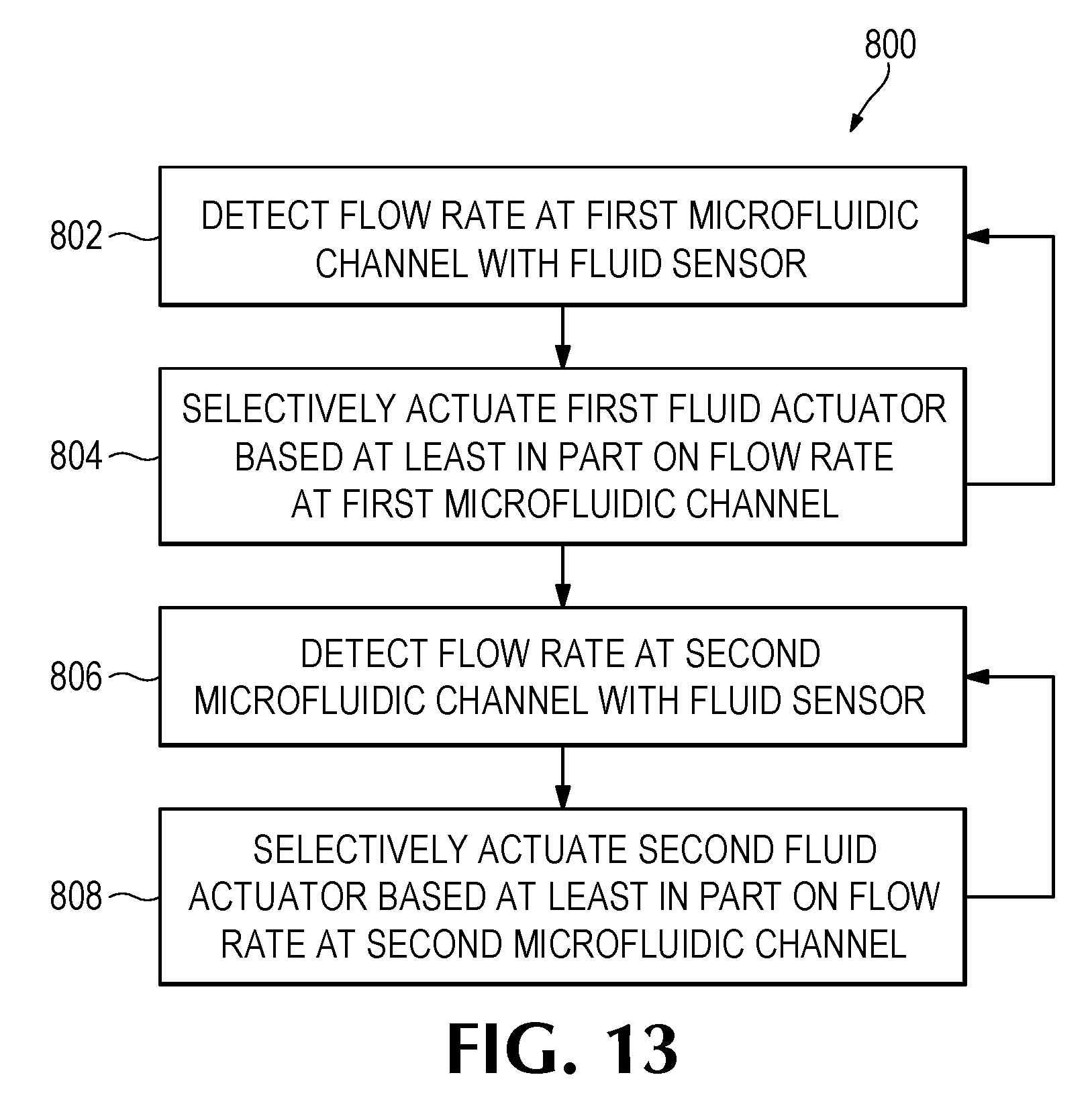
[0062] FIG. 13 provides a flowchart 800 that illustrates a sequence of operations that may be performed by an example microfluidic device and/or a controller thereof. The device may detect a flow rate at a first microfluidic channel with a first fluid sensor disposed in the first microfluidic channel (block 802). The device may selectively actuate a first fluid actuator disposed in the first microfluidic channel based at least in part on the flow rate at the first microfluidic channel (block 804) to thereby pump a first fluid into a microfluidic output channel fluidly connected to the first microfluidic channel. As shown, the device may continue detecting the flow rate at the first microfluidic channel and selectively actuating the first fluid actuator based on the flow rate at the first microfluidic channel. Concurrent with the operations of blocks 802-804, the device may detect a flow rate at a second microfluidic channel with a second fluid sensor disposed in the second microfluidic channel (block 806). The device may selectively actuate a second fluid actuator disposed in the second microfluidic channel based at least in part on the flow rate at the second microfluidic channel (block 808). As shown, the example device may continue detecting the flow rate at the second microfluidic channel and selectively actuating the second fluid actuator based on the flow rate at the second microfluidic channel.
[0063] As will be appreciated, in the example of FIG. 13, the device may selectively actuate the first fluid actuator and the second fluid actuator in an alternating manner. In some examples, such actuation timing may be described as asynchronous. Furthermore, some examples may detect flow rates associated with pumping of fluids into the microfluidic output channel, and, in such examples, further pumping of such fluids may be based at least in part on the flow rates. Accordingly, in these examples, a feedback loop may be implemented such that further actuation of fluid actuators may be adjusted based on such flow rates, where it will be appreciated that the flow rates may correspond to mixing ratios of fluids in the fluid mixture of the microfluidic output channel, a concentration of each fluid in the fluid mixture, and/or a volume of each fluid in the fluid mixture.
[0064] FIG. 14 provides a flowchart 850 that illustrates a sequence of operations that may be performed by an example microfluidic device and/or a controller thereof. In this example, based on a desired concentration of a first fluid and a second fluid to be in a fluid mixture of a microfluidic output channel (block 852), the microfluidic device may pump, with a first fluid actuator disposed in a first microfluidic channel, a first fluid into the microfluidic output channel based at least in part on the concentration of the first fluid to be in the fluid mixture (block 854), and the device may pump, with a second fluid actuator disposed in a second microfluidic channel, a second fluid into the microfluidic output channel based at least in part on the concentration of the second fluid to be in the fluid mixture (block 856). As will be appreciated, pumping of fluid corresponds to actuation of a fluid actuator. Accordingly, actuation of the first fluid actuator may be based at least in part on the concentration of the first fluid to be in the fluid mixture, and actuation of the second fluid actuator may be based at least in part on the concentration of the second fluid to be in the mixture.
[0065] FIG. 15 provides a flowchart 900 that illustrates a sequence of operations that may be performed by an example microfluidic device. In this example, the microfluidic device may comprise a first set of fluid actuators disposed in a first microfluidic channel and a second fluid actuator disposed in a second microfluidic channel. The microfluidic device may pump a first volume of a first fluid with a first subset of the fluid actuators of the first set into the microfluidic output channel (block 902). The microfluidic device may pump a second fluid with the second fluid actuator into the microfluidic output channel (block 904). The example device may pump a second volume of the first fluid into the microfluidic output channel with a second subset of fluid actuators of the first set (block 906). Accordingly, in examples in which at least two fluid actuators are disposed in a common microfluidic channel, such examples may selectively actuate each fluid actuator individually or in various combinations to cause pumping of different volumes of fluid.
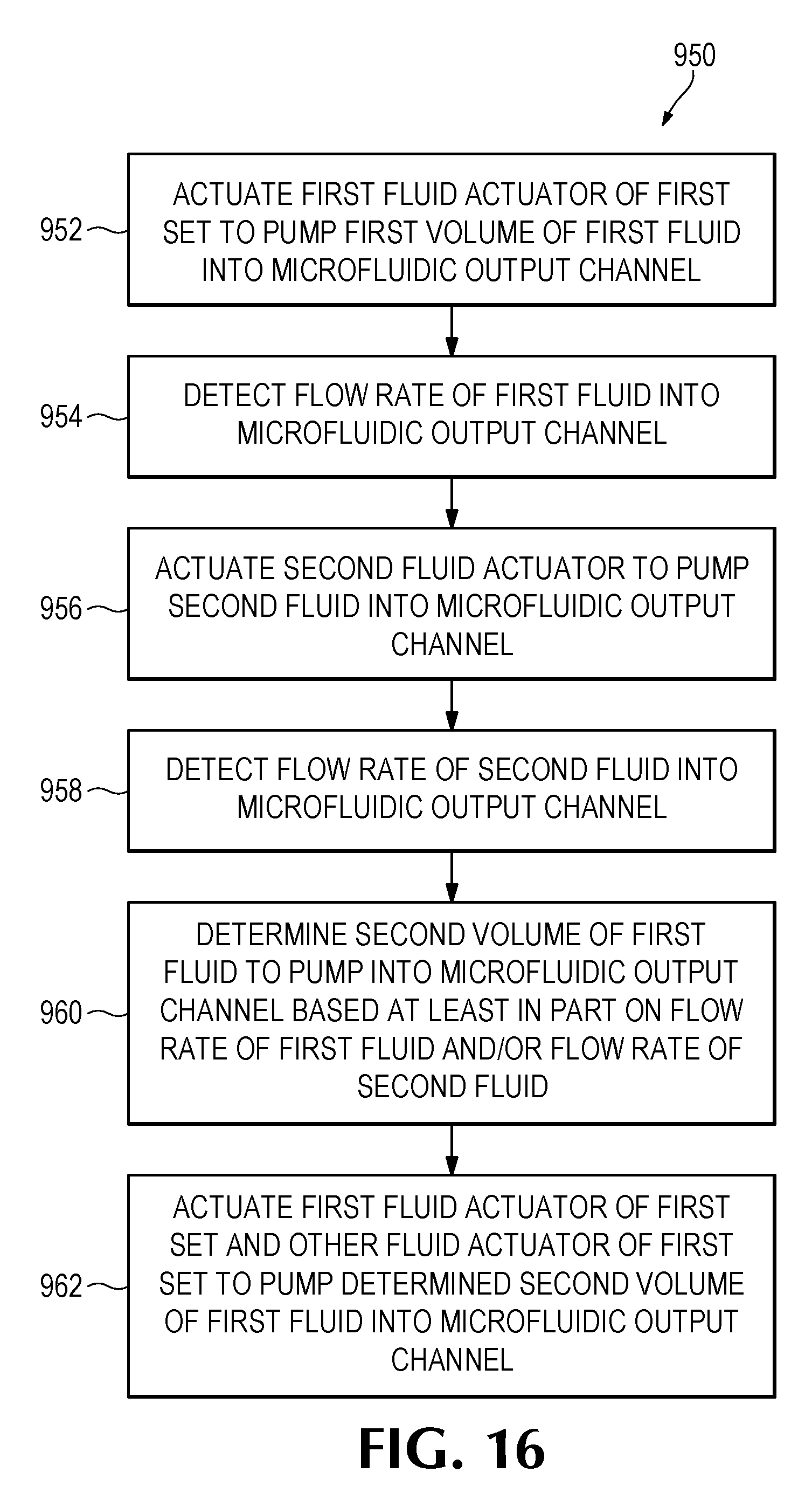
[0066] FIG. 16 provides a flowchart 950 that illustrates an example sequence of operations that may be performed by an example microfluidic device and/or a controller thereof. In this example, the microfluidic device may comprise a first set of fluid actuators disposed in a first microfluidic channel and a second fluid actuator disposed in a second microfluidic channel. As shown, the device actuates a first fluid actuator of the first set of fluid actuators to pump a first volume of a first fluid into the microfluidic output channel (block 952). The device detects a flow rate of the first fluid into the microfluidic output channel (block 954). The device actuates the second fluid actuator to pump a second fluid into the microfluidic output channel (block 956). The device detects a flow rate of the second fluid into the microfluidic output channel (block 958). The device determines a second volume of the first fluid to pump into the microfluidic output channel based at least in part on the flow rate of the first fluid and/or the flow rate of the second fluid (block 960). The device actuates the first fluid actuator and at least one other fluid actuator of the first set to pump the determined second volume of the first fluid into the microfluidic output channel (block 962).
[0067] Accordingly, the examples described herein provide examples of a microfluidic device in which fluids may be pumped into a fluid mixture at a desired concentration. In these examples, microfluidic channels may facilitate input of at least two different fluids. Fluid actuators disposed in the microfluidic channels may facilitate precise pumping of discrete volumes of such fluids into a microfluidic output channel to thereby pump a fluid mixture into the microfluidic channel. As will be appreciated, example devices as described herein may facilitate manipulation of small volumes of fluid (e.g., approximately 1 nL to approximately 1 pL). Because examples described herein facilitate manipulation and mixing of such small volumes of fluid, examples may be implemented for precision fluid mixing devices and/or as components in fluid processing devices.
[0068] In addition, while various examples are described herein, elements and/or combinations of elements may be combined and/or removed for various examples contemplated hereby. For example, the example operations provided herein in the flowcharts of FIGS. 11-16 may be performed sequentially, concurrently, or in a different order. Moreover, some example operations of the flowcharts may be added to other flowcharts, and/or some example operations may be removed from flowcharts. Furthermore, in some examples, various components of the example systems of FIGS. 1-10 may be removed, and/or other components may be added.
[0069] The preceding description has been presented to illustrate and describe examples of the principles described. This description is not intended to be exhaustive or to limit these principles to any precise form disclosed. Many modifications and variations are possible in light of the above disclosure.
* * * * *
D00000
D00001
D00002
D00003
D00004
D00005
D00006
D00007
D00008
D00009
D00010
D00011
D00012
D00013
XML
uspto.report is an independent third-party trademark research tool that is not affiliated, endorsed, or sponsored by the United States Patent and Trademark Office (USPTO) or any other governmental organization. The information provided by uspto.report is based on publicly available data at the time of writing and is intended for informational purposes only.
While we strive to provide accurate and up-to-date information, we do not guarantee the accuracy, completeness, reliability, or suitability of the information displayed on this site. The use of this site is at your own risk. Any reliance you place on such information is therefore strictly at your own risk.
All official trademark data, including owner information, should be verified by visiting the official USPTO website at www.uspto.gov. This site is not intended to replace professional legal advice and should not be used as a substitute for consulting with a legal professional who is knowledgeable about trademark law.