Robot Vacuum Cleaner
Zhu; Xiaogang ; et al.
U.S. patent application number 16/125788 was filed with the patent office on 2019-10-03 for robot vacuum cleaner. The applicant listed for this patent is JIANGSU MIDEA CLEANING APPLIANCES CO., LTD., MIDEA GROUP CO., LTD.. Invention is credited to Manzhi Jin, Xianmin Wei, Xiaogang Zhu.
| Application Number | 20190298120 16/125788 |
| Document ID | / |
| Family ID | 68056563 |
| Filed Date | 2019-10-03 |
| United States Patent Application | 20190298120 |
| Kind Code | A1 |
| Zhu; Xiaogang ; et al. | October 3, 2019 |
ROBOT VACUUM CLEANER
Abstract
The present application discloses a robot vacuum cleaner, including a cover, a dust collection box and a button assembly, the button assembly being disposed to one of the cover and the dust collection box, the button assembly including a button and a retractable block, the button being connected to the block, the other of the cover and the dust collection box being provided with a socket, the block being snap-fitted in the socket so as to install the dust collection box to the cover, when the button is operated, the block is driven to retract so as to make the block to be separated from the socket.
| Inventors: | Zhu; Xiaogang; (Suzhou, CN) ; Wei; Xianmin; (Suzhou, CN) ; Jin; Manzhi; (Suzhou, CN) | ||||||||||
| Applicant: |
|
||||||||||
|---|---|---|---|---|---|---|---|---|---|---|---|
| Family ID: | 68056563 | ||||||||||
| Appl. No.: | 16/125788 | ||||||||||
| Filed: | September 10, 2018 |
Related U.S. Patent Documents
| Application Number | Filing Date | Patent Number | ||
|---|---|---|---|---|
| PCT/CN2018/098028 | Aug 1, 2018 | |||
| 16125788 | ||||
| Current U.S. Class: | 1/1 |
| Current CPC Class: | A47L 9/1427 20130101; A47L 2201/024 20130101; A47L 9/1409 20130101; A47L 9/106 20130101; A47L 2201/00 20130101; A47L 5/00 20130101 |
| International Class: | A47L 5/00 20060101 A47L005/00; A47L 9/10 20060101 A47L009/10 |
Foreign Application Data
| Date | Code | Application Number |
|---|---|---|
| Mar 30, 2018 | CN | 201820465505.9 |
Claims
1. A robot vacuum cleaner, comprising: a cover, a dust collection box, and a button assembly; and, wherein the button assembly is disposed at the cover, and comprises a button and a retractable block, the button being connected to the retractable block; and the dust collection box is provided with a socket, wherein the retractable block is configured to be snap-fitted in the socket to install the dust collection box to the cover, wherein when the button is pressed, the retractable block is driven to be retracted from the socket with only one press; wherein the button comprises: a pressing portion and a first resisting portion, the first resisting portion being disposed below the pressing portion, and a second resisting portion connected to the retractable block, wherein when the button is pressed downwards, the first resisting portion is abutted against the second resisting portion and drives the second resisting portion to lead the retractable block to be retracted from the socket; wherein the first resisting portion comprises a first inclined surface, the second resisting portion comprises a second inclined surface, when the button is pressed downwards, the first inclined surface is abutted against the second inclined surface to provide driving force for retraction of the retractable block.
2. The robot vacuum cleaner according to claim 1, wherein the cover is provided with an accommodating hole, when the dust collection box is mounted to the cover, the dust collection box is at least partially located in the accommodating hole and the button assembly is arranged at a side wall of the accommodating hole.
3. The robot vacuum cleaner according to claim 1, wherein the button assembly is disposed at a side wall of the cover and the dust collection box is mounted to a side wall of the cover.
4-5. (canceled)
6. The robot vacuum cleaner according to claim 1, wherein the first inclined surface and the second inclined surface are parallel with each other.
7. The robot vacuum cleaner according to claim 1, wherein the button assembly comprises a first elastic piece, the first elastic piece is connected to the retractable block and configured to provide driving force for extension of the retractable block, and when the retractable block is retracted, the first elastic piece is compressed.
8. The robot vacuum cleaner according to claim 7, wherein the retractable block is provided with a blind hole and an end of the first elastic piece is disposed in the blind hole.
9. The robot vacuum cleaner according to claim 1, wherein the button assembly comprises a second elastic piece, the second elastic piece is connected to the button, and the second elastic piece is configured to provide driving force for reset of the button.
10. The robot vacuum cleaner according to claim 2, wherein an end of the retractable block is provided with a third inclined surface, the dust collection box is provided with a protruding block, during an installation process of the dust collection box to the cover, wherein the protruding block is abutted against the third inclined surface to drive the retractable block to retract, and when the protruding block is separated from the third inclined surface, the retractable block extends out and is snap-fitted in the socket.
11. The robot vacuum cleaner according to claim 2, wherein the button assembly comprises a back plate, the button and the retractable block are movably connected to the back plate, and the back plate is fixed to the cover.
12. The robot vacuum cleaner according to claim 1, wherein two blocks are provided, and the button assembly comprises a connecting portion connecting the two blocks.
13. A robot vacuum cleaner, comprising: a cover, a dust collection box, and a button assembly; and, wherein the button assembly is disposed at the dust collection box, and comprises a button and a retractable block, the button being connected to the retractable block; and the cover is provided with a socket, wherein the retractable block is configured to be snap-fitted in the socket to install the dust collection box to the cover, wherein when the button is pressed, the retractable block is driven to be retracted from the socket with only one press; wherein the button comprises: a pressing portion and a first resisting portion, the first resisting portion being disposed below the pressing portion, and a second resisting portion connected to the retractable block, wherein when the button is pressed downwards, the first resisting portion is abutted against the second resisting portion and drives the second resisting portion to lead the retractable block to be retracted from the socket; wherein the first resisting portion comprises a first inclined surface, the second resisting portion comprises a second inclined surface, when the button is pressed downwards, the first inclined surface is abutted against the second inclined surface to provide driving force for retraction of the retractable block.
14. The robot vacuum cleaner according to claim 3, wherein the cover is provided with an accommodating hole, when the dust collection box is mounted to the cover, the dust collection box is at least partially located in the accommodating hole and the button assembly is arranged at a side wall of the accommodating hole.
15. The robot vacuum cleaner according to claim 13, wherein the button assembly is disposed at a side wall of the cover and the dust collection box is mounted to a side wall of the cover.
16. The robot vacuum cleaner according to claim 13, wherein the button comprises: a pressing portion and a first resisting portion, the first resisting portion being disposed below the pressing portion, and a second resisting portion connected to the retractable block, wherein when the button is pressed downwards, the first resisting portion is abutted against the second resisting portion and drives the second resisting portion to lead the retractable block to be retracted from the socket.
17. The robot vacuum cleaner according to claim 13, wherein the button assembly comprises a first elastic piece, the first elastic piece is connected to the retractable block and configured to provide driving force for extension of the retractable block, and when the retractable block is retracted, the first elastic piece is compressed.
18. The robot vacuum cleaner according to claim 13, wherein the button assembly comprises a second elastic piece, the second elastic piece is connected to the button, and the second elastic piece is configured to provide driving force for reset of the button.
19. The robot vacuum cleaner according to claim 14, wherein an end of the retractable block is provided with a third inclined surface, the dust collection box is provided with a protruding block, during an installation process of the dust collection box to the cover, wherein the protruding block is abutted against the third inclined surface to drive the retractable block to retract, and when the protruding block is separated from the third inclined surface, the retractable block extends out and is snap-fitted in the socket.
20. The robot vacuum cleaner according to claim 14, wherein the button assembly comprises a back plate, the button and the retractable block are movably connected to the back plate, and the back plate is fixed to the cover.
Description
[0001] This application is a continuation of International Application No. PCT/CN2018/098028, filed on Aug. 1, 2018, which claims priority to and the benefit of Chinese Patent Application No. 201820465505.9 filed in the China's State Intellectual Property Office on Mar. 30, 2018, the entire contents of which are incorporated herein by reference.
FIELD
[0002] The present disclosure relates to a technical field of household appliances, and more particularly to a robot vacuum cleaner.
BACKGROUND
[0003] In the related art, a dust collection box is directly mounted to a robot body in a robot vacuum cleaner relying on a guiding action of the dust collection box itself inside the robot body of the robot vacuum cleaner, no position limiting structure exists and the dust collection box is tightly fitted with the robot body. However, when a user needs to take out the dust collection box to clean the dust, because the dust collection box is too tightly fitted to the robot body, a greater force is required to remove the dust collection box and it is inconvenient to operate. At the same time, the dust collection box or components in contact with the dust collection box tend to deform and the life of the product is influenced.
SUMMARY
[0004] Embodiments of the present disclosure provide a robot vacuum cleaner.
[0005] The robot vacuum cleaner according to embodiments of the present disclosure includes a cover, a dust collection box and a button assembly. The button assembly is disposed to one of the cover and the dust collection box, the button assembly includes a button and a retractable block. The button is connected to the block, the other of the cover and the dust collection box is provided with a socket, the block is snap-fitted in the socket so as to install the dust collection box to the cover, when the button is operated, the block is driven to retract so as to make the block to be separated from the socket.
[0006] In the robot vacuum cleaner according to embodiments of the present disclosure, the dust collection box can be mounted to the cover through the block being fitted the socket, and the user can remove the dust collection box by operating the button. In this way, the operation difficulty of removing the dust collection box by the user is reduced. Moreover, the dust collection box is installed or detached by the extension and retraction of the block, thereby effectively reducing deformation possibility of various components of the dust collection box or the robot vacuum cleaner and hence ensuring product life.
[0007] In some embodiments, the button assembly is disposed to the cover and the dust collection box is provided with the socket.
[0008] In some embodiments, the cover is provided with an accommodating hole, when the dust collection box is mounted to the cover, the dust collection box is at least partially located in the accommodating hole and the button assembly is arranged at a side wall of the accommodating hole.
[0009] In some embodiments, the button assembly is disposed at a side wall of the cover and the dust collection box is mounted to a side wall of the cover.
[0010] In some embodiments, the button includes a pressing portion and a first resisting portion, the first resisting portion is disposed below the pressing portion, the button assembly includes a second resisting portion connected to the block, when the button is pressed downwards, the first resisting portion is abutted against the second resisting portion and drives the second resisting portion to lead the block to retract so as to make the block to be separated from the socket.
[0011] In some embodiments, the first resisting portion includes a first inclined surface, the second resisting portion includes a second inclined surface, when the button is pressed downwards, the first inclined surface is abutted against the second inclined surface so as to provide driving force for retraction of the block.
[0012] In some embodiments, the first inclined surface and the second inclined surface are parallel with each other.
[0013] In some embodiments, the button assembly includes a first elastic piece, the first elastic piece is connected to the block and configured to provide driving force for extension of the block, and when the block is retracted, the first elastic piece is compressed.
[0014] In some embodiments, the block is provided with a blind hole and an end of the first elastic piece is disposed in the blind hole.
[0015] In some embodiments, the button assembly includes a second elastic piece, the second elastic piece is connected to the button, and the second elastic piece is configured to provide driving force for reset of the button.
[0016] In some embodiments, an end of the block is provided with a third inclined surface, the dust collection box is provided with a protruding block, during an installation process of the dust collection box to the cover, the protruding block is abutted against the third inclined surface so as to drive the block to retract, and when the protruding block is separated from the third inclined surface, the block extends out and is snap-fitted in the socket.
[0017] In some embodiments, the button assembly includes a back plate, the button and the block are movably connected to the back plate, and the back plate is fixed to the cover.
[0018] In some embodiments, two blocks are provided, and the button assembly includes a connecting portion connecting the two blocks.
[0019] Additional aspects and advantages of embodiments of present disclosure will be given in part in the following descriptions, become apparent in part from the following descriptions, or be learned from the practice of the embodiments of the present disclosure.
BRIEF DESCRIPTION OF THE DRAWINGS
[0020] These and/or other aspects and advantages of the present disclosure will become apparent and more readily appreciated from the following descriptions of embodiments made with reference to the drawings, in which:
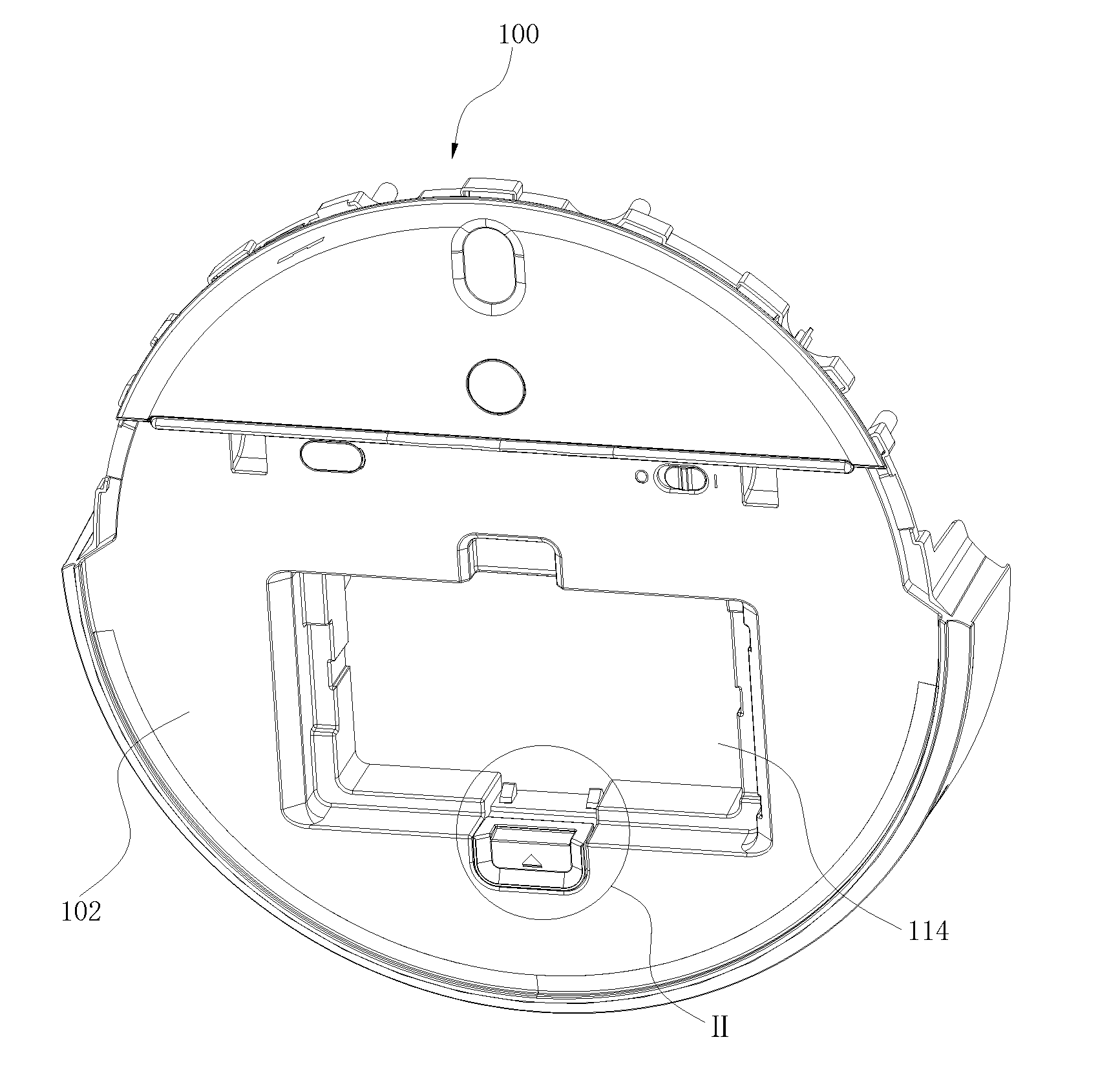
[0021] FIG. 1 is a partial sectional view of a robot vacuum cleaner according to embodiments of the present application;
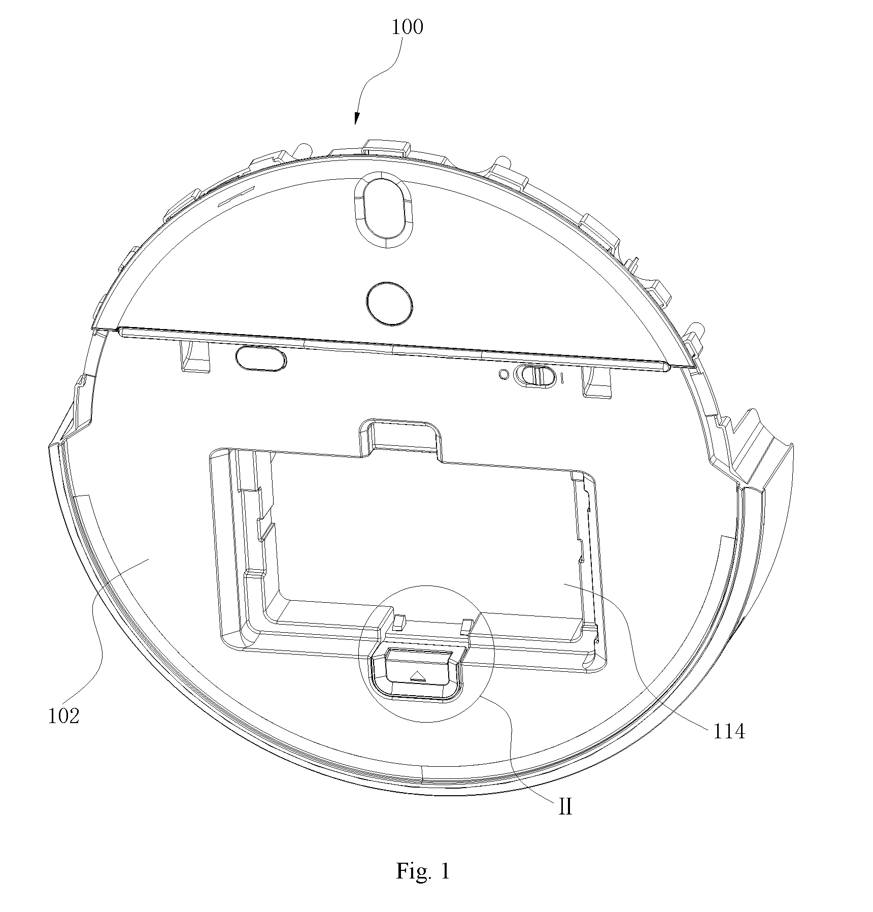
[0022] FIG. 2 is an enlarged view of part II of the robot vacuum cleaner in FIG. 1.
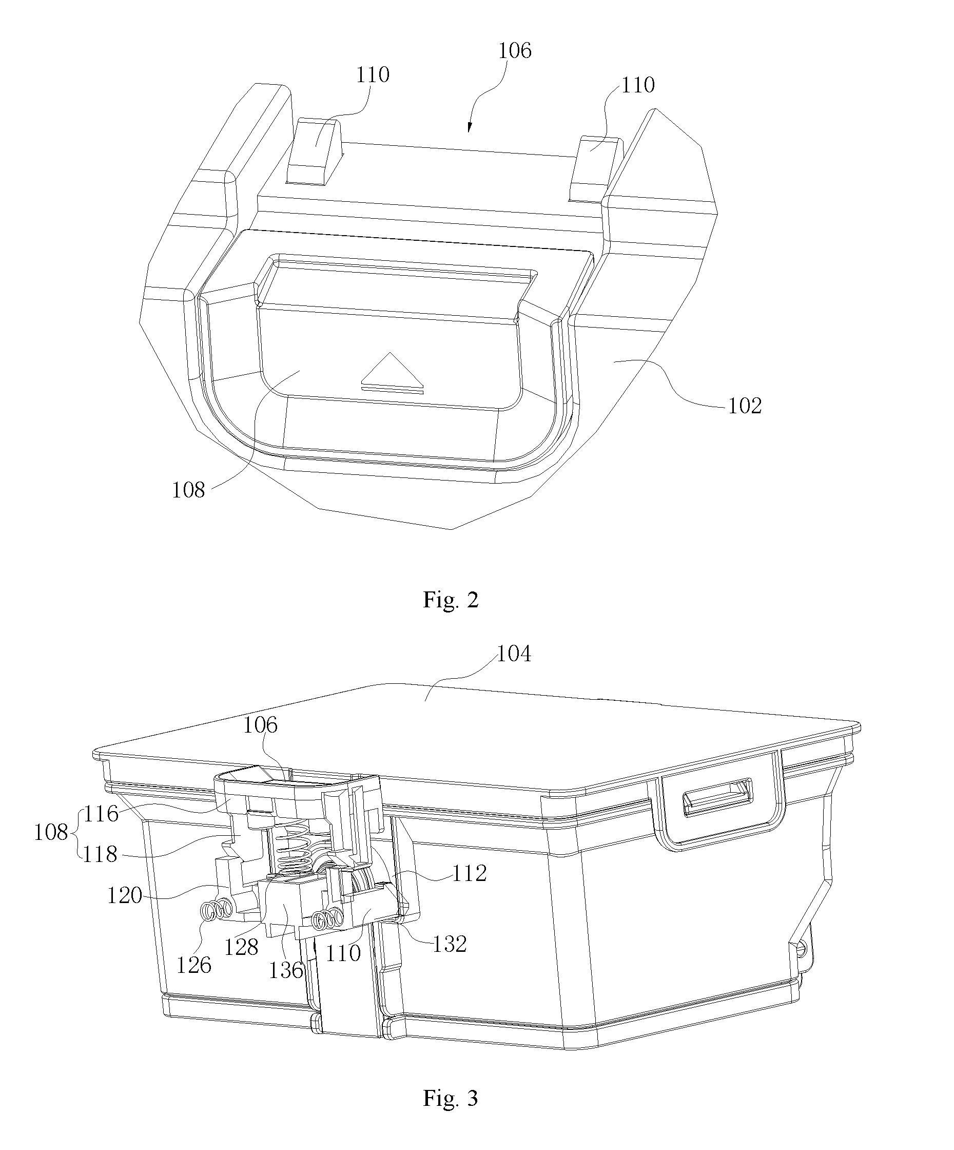
[0023] FIG. 3 is a perspective view of a dust collection box and a button assembly according to embodiments of the present application.
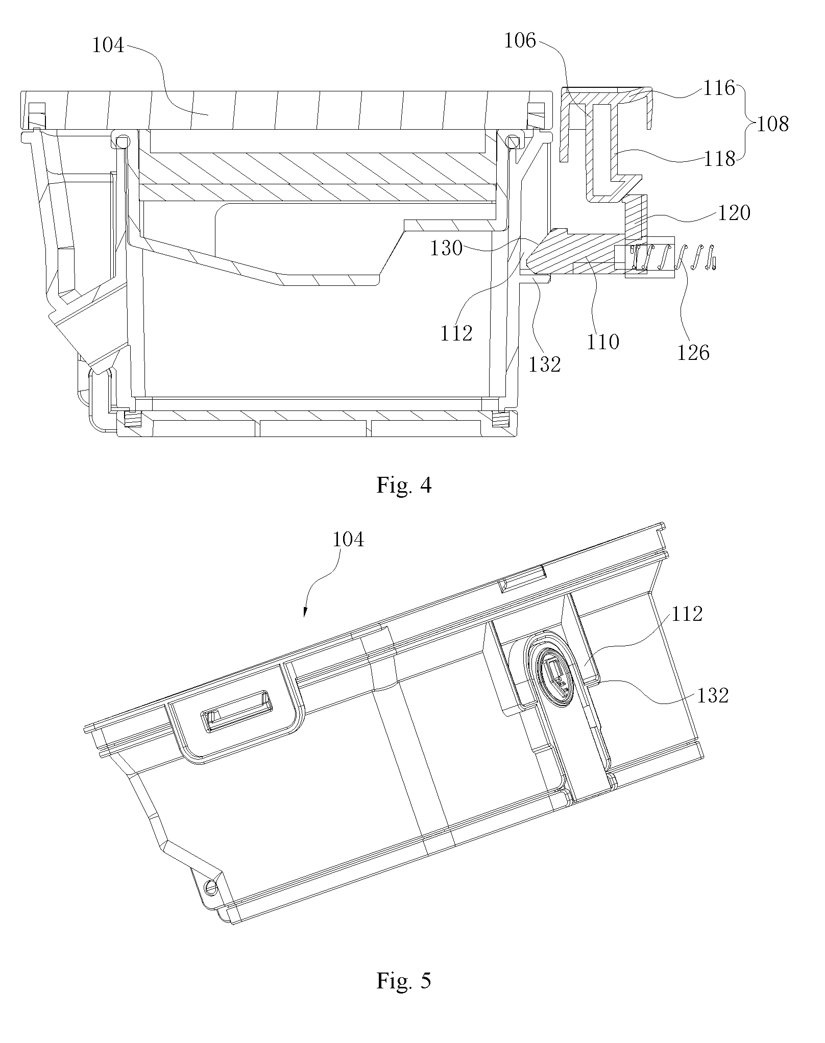
[0024] FIG. 4 is a sectional view of a dust collection box and a button assembly according to embodiments of the present application.
[0025] FIG. 5 is a perspective view of a dust collection box according to embodiments of the present application.
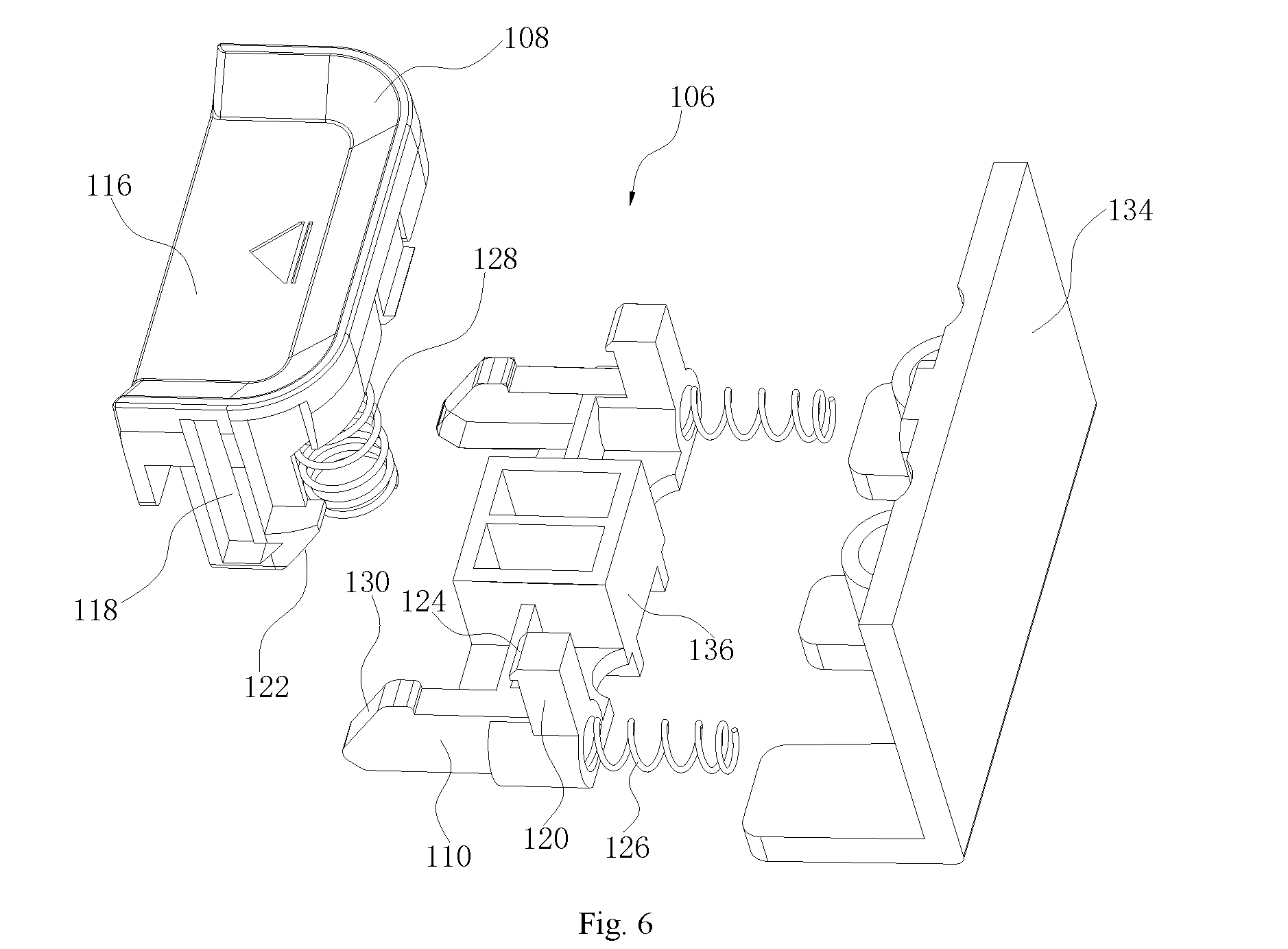
[0026] FIG. 6 is an exploded view of a button assembly according to embodiments of the present application.
MAIN REFERENCE NUMERALS
[0027] robot vacuum cleaner 100, cover 102, dust collection box 104, button assembly 106, button 108, block 110, socket 112, accommodating hole 114, pressing portion 116, first resisting portion 118, second resisting portion 120, first inclined surface 122, second inclined surface 124, first elastic piece 126, second elastic piece 128, third inclined surface 130, protruding block 132, back plate 134, connecting portion 136.
DETAILED DESCRIPTION
[0028] Reference will be made in detail to embodiments of the present disclosure. Examples of the embodiments are shown in the drawings. The same or similar elements and the elements having same or similar functions are denoted by like reference numerals throughout the descriptions. The embodiments described herein with reference to drawings are explanatory, illustrative, and used to generally understand the present disclosure. The embodiments shall not be construed to limit the present disclosure.
[0029] In the specification, it is to be understood that terms such as "central," "longitudinal," "transverse," "length," "width," "thickness," "upper," "lower," "front," "rear," "left," "right," "vertical," "horizontal," "top," "bottom," "inner," "outer," "clockwise," and "counterclockwise" should be construed to refer to the orientation as then described or as shown in the drawings under discussion. These relative terms are for convenience of description and do not require that the present disclosure have a particular orientation or be constructed or operated in a particular orientation. Thus, these terms cannot be constructed to limit the present disclosure. In addition, terms such as "first" and "second" are used herein for purposes of description and are not intended to indicate or imply relative importance or significance or to imply the number of indicated technical features. Thus, the feature defined with "first" and "second" may comprise one or more of this feature. In the description of the present disclosure, "a plurality of" means two or more than two, unless specified otherwise.
[0030] In the description of the present disclosure, it should be understood that, unless specified or limited otherwise, the terms "mounted," "connected," and "coupled" and variations thereof are used broadly and may be, for example, fixed connections, detachable connections, or integral connections; may also be mechanical or electrical connections; may also be direct connections or indirect connections via intervening structures; may also be inner communications or interaction of two elements, which can be understood by those skilled in the art according to specific situations.
[0031] Referring to FIG. 1 to FIG. 6 together, a robot vacuum cleaner 100 in accordance with the present disclosure can include a cover 102, a dust collection box 104 and a button assembly 106. The button assembly 106 may be disposed at the cover 102 or the dust collection box 104. As shown, the button assembly 106 includes a button 108 and a retractable block 110 and the button 108 is connected with the block 110. When the button assembly 106 is disposed at the cover 102, the dust collection box 104 may be provided with the socket 112. However, this is not necessarily the only case. When the button assembly 106 is disposed at the dust collection box 104, as shown in this example, the cover 102 may be provided with a socket 112. In any case, the block 110 is snap-fitted in the socket 112 so as to install the dust collection box 104 to the cover 102, and when the button 108 is operated, the block 110 is driven to retract so as to make the block 110 to be separated from the socket 112.
[0032] In the robot vacuum cleaner 100 according to the present disclosure, the dust collection box 104 can be mounted to the cover 102 through the block 110 in the socket 112, and the user can remove the dust collection box 104 by pressing the button 108 only once. In this way, the operation difficulty of removing the dust collection box 104 by the user may be reduced. Moreover, the dust collection box 104 is installed or detached by the extension and retraction of the block 110, thereby effectively reducing deformation possibility of various components of the dust collection box 104 or the robot vacuum cleaner 100 and hence ensuring product life.
[0033] It will be understood that when the user wants to install the dust collection box 104, the dust collection box 104 can placed in the cover 102 and begins to move down. During the downward movement, the block 110 is snap-fitted in the socket 112 so as to fit the dust collection box 104 to the cover 102. When the user removes the dust collection box 104, the button 108 can be operated, for example, by pressing the button 108, and the block 110 is driven to retract so that the block 110 is separated from the socket 112, and in this case, the dust collection box 104 can be removed with only a small force. In the present embodiment, the dust collection box 104 can be installed or detached by the retraction and extension of the block 110, a gap may exist between the dust collection box 104 and the cover 102 so as to prevent the dust collection box 104 from being fitted with the cover 102 too tightly, and only a small force is required to remove the dust collection box 104, thereby effectively reducing the deformation possibility of each component (especially the components in contact with the dust collection box 104) of the dust collection box 104 or the robot vacuum cleaner 100, and hence further ensuring product life.
[0034] In this embodiment, the button assembly 106 is disposed to the cover 102 and the dust collection box 104 is provided with the socket 112. Thus, the dust collection box 104 can be installed to the cover 102 by the block 110 being fitted in the socket 112, the user can remove the dust collection box 104 by operating the button 108. In another embodiment, the button assembly 106 can be disposed in the dust collection box 104, and the cover 102 is provided with the socket 112.
[0035] In some embodiments, the cover 102 is provided with an accommodating hole 114, when the dust collection box 104 is mounted to the cover 102, the dust collection box 104 is at least partially located in the accommodating hole 114 and the button assembly 106 is arranged at a side wall of the accommodating hole 114.
[0036] It could be understood that when the dust collection box 104 is placed in the robot body of the robot vacuum cleaner 100 i.e. when the dust collection box 104 is mounted to the cover 102, the dust collection box 104 is at least partially located in the accommodating hole 114 provided in the cover 102. The button assembly 106 is disposed to the side wall of the accommodating hole 114, which is beneficial for the socket 112 of the dust collection box 104 to be fitted with the block 110 of the button assembly 106 so as to install the dust collection box 104. With the dust collection box 104 being at least partially located in the accommodating hole 114 provided in the cover 102, it is possible to reduce a volume of the robot vacuum cleaner. Certainly, in other embodiments, the cover 102 may not be provided with the accommodating hole 114, and the button assembly 106 can be disposed at a side wall of the cover 102 and the dust collection box 104 can be mounted to a side wall of the cover 102 directly.
[0037] In some embodiments, the button 108 includes a pressing portion 116 and a first resisting portion 118, the first resisting portion 118 is disposed below the pressing portion 116, the button assembly 106 includes a second resisting portion 120 connected to the block 110, when the button 108 is pressed downwards, the first resisting portion 118 is abutted against the second resisting portion 120 and drives the second resisting portion 120 to lead the block 110 to retract so as to make the block 110 to be separated from the socket 112.
[0038] It may be understood that when the button 108 is pressed downwards, the first resisting portion 118 is abutted against the second resisting portion 120, and the second resisting portion 120 is forced to retract the block 110 being connected with the second resisting portion 120, thereby the block 110 is separated from the socket 112, and the dust collection box 104 can be removed with only a small force.
[0039] In some embodiments, the first resisting portion 118 includes a first inclined surface 122, the second resisting portion 120 includes a second inclined surface 124, when the button 108 is pressed downwards, the first inclined surface 122 is abutted against the second inclined surface 124 so as to provide driving force for retraction of the block 110.
[0040] It could be understood that the first inclined surface 122 and the second inclined surface 124 are parallel with each other. When the button 108 is pressed downwards, the first inclined surface 122 is abutted against the second inclined surface 124 so as to provide greater driving force for the retraction of the block 110.
[0041] In some embodiments, the button assembly 106 includes a first elastic piece 126, the first elastic piece 126 is connected to the block 110 and configured to provide driving force for extension of the block 110, and when the block 110 is retracted, the first elastic piece 126 is compressed.
[0042] It could be understood that the first elastic piece 126 is connected to the block 110, and when the second resisting portion 120 is forced to drive the block 110 to retract, the first elastic piece 126 is compressed; when the first elastic piece 126 recovers to its original length, under effect of restoring force of the first elastic piece 126, the block 110 extends out. For example, the block 110 is provided with a blind hole and an end of the first elastic piece 126 is disposed in the blind hole. Preferably, the end of the first elastic piece 126 is fixedly connected to the blind hole. The first elastic piece 126 can be a spring.
[0043] In some embodiments, the button assembly 106 includes a second elastic piece 128, the second elastic piece 128 is connected to the button 108, and the second elastic piece 128 is configured to provide driving force for reset of the button 108.
[0044] It could be understood that when the button 108 is pressed downwards, the second elastic piece 128 is compressed, and when the force pressing the button 108 is withdrawn, the second elastic piece 128 recovers to its original length, and under effect of restoring force of the second elastic piece 128, the button 108 is reset. Further, two blocks 110 are provided, and the button assembly 106 includes a connecting portion 136 connecting the two blocks 110. An end of the second elastic piece 128 can be connected to the button 108, and the other end of the second elastic piece 128 is abutted against the connecting portion 136. Thus, the second elastic piece 128 can be compressed. The second elastic piece 128 can be a spring.
[0045] In some embodiments, an end of the block 110 is provided with a third inclined surface 130, the dust collection box 104 is provided with a protruding block 132, during an installation process of the dust collection box 104 to the cover 102, the protruding block 132 is abutted against the third inclined surface 130 so as to drive the block 110 to retract, and when the protruding block 132 is separated from the third inclined surface 130, the block 110 extends out and is snap-fitted in the socket 112.
[0046] It could be understood that, during the installation process of the dust collection box 104 to the cover 102, the protruding block 132 is abutted against the third inclined surface 130 of the block 110, interaction force is generated between the protruding block 132 and the block 110, and the block 110 is forced to retract. When the protruding force 132 is separated from the third inclined surface 130, the interaction force between the protruding block 132 and the block 110 disappears, the block 110 extends out and is snap-fitted in the socket 112, and the installation of the dust collection box 104 is finished.
[0047] In some embodiments, the button assembly 106 includes a back plate 134, the button 108 and the block 110 are movably connected to the back plate 134, and the back plate 134 is fixed to the cover 102.
[0048] It could be understood that the button 108 and the block 110 can be connected to the back plate 134 movably, the back plate 134 is configured to abut the first elastic piece 126, so that the first elastic piece 126 can be compressed. Specifically, the back plate 134 can be fixed to the cover 102 by means of screws.
[0049] In some embodiments, two blocks 110 are provided, and the button assembly 106 includes a connecting portion 136 connecting the two blocks 110.
[0050] Thus, two blocks 110 are fitted with two sockets 112, which can install the dust collection box 104 to the cover 102 better, so that the installation of the dust collection box 104 is more stably.
[0051] In some embodiments, the number of the sockets 112 can be consistent with the number of the block 110. For example, in FIG. 5, two sockets 112 are provided, each block 110 is snap-fitted in the socket 112 correspondingly. Certainly, one socket 112 can be provided, and the one socket 112 can be formed more largely so that both the two blocks 110 can be snap-fitted into the socket 112.
[0052] In the present disclosure, unless specified or limited otherwise, a structure in which a first feature is "on" or "below" a second feature may include an embodiment in which the first feature is in direct contact with the second feature, and may also include an embodiment in which the first feature and the second feature are not in direct contact with each other, but are contacted via an additional feature formed therebetween. Furthermore, a first feature "on," "above," or "on top of" a second feature may include an embodiment in which the first feature is right or obliquely "on," "above," or "on top of" the second feature, or just means that the first feature is at a height higher than that of the second feature; while a first feature "below," "under," or "on bottom of" a second feature may include an embodiment in which the first feature is right or obliquely "below," "under," or "on bottom of" the second feature, or just means that the first feature is at a height lower than that of the second feature.
[0053] Various embodiments and examples are provided in the following description to implement different structures of the present disclosure. In order to simplify the present disclosure, certain elements and settings are described above. However, these elements and settings are only by way of example and are not intended to limit the present disclosure. In addition, reference numerals and/or reference letters may be repeated in different examples in the present disclosure.
[0054] This repetition is for the purpose of simplification and clarity, and does not refer to relations between different embodiments and/or settings. Furthermore, examples of different processes and materials are provided in the present disclosure. However, it would be appreciated by those skilled in the art that other processes and/or materials may be also applied.
[0055] Reference throughout this specification to "an embodiment," "some embodiments," "an exemplary embodiment," "an example," "specific examples" or "some examples" means that a particular feature, structure, material, or characteristic described in connection with the embodiment or example is included in at least one embodiment or example of the present disclosure. Thus, the appearances of the above phrases throughout this specification are not necessarily referring to the same embodiment or example of the present disclosure. Furthermore, the particular features, structures, materials, or characteristics may be combined in any suitable manner in one or more embodiments or examples.
[0056] Although embodiments of the present disclosure have been shown and illustrated, it shall be understood by those skilled in the art that various changes, modifications, alternatives and variations without departing from the principle of the present disclosure are acceptable. The scope of the present disclosure is defined by the claims or the like.
* * * * *
D00000
D00001
D00002
D00003
D00004
XML
uspto.report is an independent third-party trademark research tool that is not affiliated, endorsed, or sponsored by the United States Patent and Trademark Office (USPTO) or any other governmental organization. The information provided by uspto.report is based on publicly available data at the time of writing and is intended for informational purposes only.
While we strive to provide accurate and up-to-date information, we do not guarantee the accuracy, completeness, reliability, or suitability of the information displayed on this site. The use of this site is at your own risk. Any reliance you place on such information is therefore strictly at your own risk.
All official trademark data, including owner information, should be verified by visiting the official USPTO website at www.uspto.gov. This site is not intended to replace professional legal advice and should not be used as a substitute for consulting with a legal professional who is knowledgeable about trademark law.