Base Seat For Bed Or Chair
SHIH; Lung-Tan
U.S. patent application number 15/942189 was filed with the patent office on 2019-10-03 for base seat for bed or chair. The applicant listed for this patent is RUOEY LUNG ENTERPRISE CORP., Lung-Tan SHIH. Invention is credited to Lung-Tan SHIH.
| Application Number | 20190298064 15/942189 |
| Document ID | / |
| Family ID | 68056466 |
| Filed Date | 2019-10-03 |


View All Diagrams
| United States Patent Application | 20190298064 |
| Kind Code | A1 |
| SHIH; Lung-Tan | October 3, 2019 |
BASE SEAT FOR BED OR CHAIR
Abstract
A base seat, which is adapted for being used with a bed or a chair, includes a fixation base, a rocking mount, a drive device, and a swivel mount. The rocking mount is disposed above the fixation base and reciprocatingly and inclinedly moveable relative to the fixation base. The drive device is disposed between the fixation base and the rocking mount to drive the rocking mount to reciprocatingly and inclinedly move relative to the fixation base. The swivel mount is disposed above the rocking mount and rotatable relative to the rocking mount. By rotating the swivel mount and driving the rocking mount to reciprocatingly and inclinedly move, the bed or chair, which is fixedly mounted to the swivel mount, is swingable in a desired direction.
| Inventors: | SHIH; Lung-Tan; (Lukang Township, TW) | ||||||||||
| Applicant: |
|
||||||||||
|---|---|---|---|---|---|---|---|---|---|---|---|
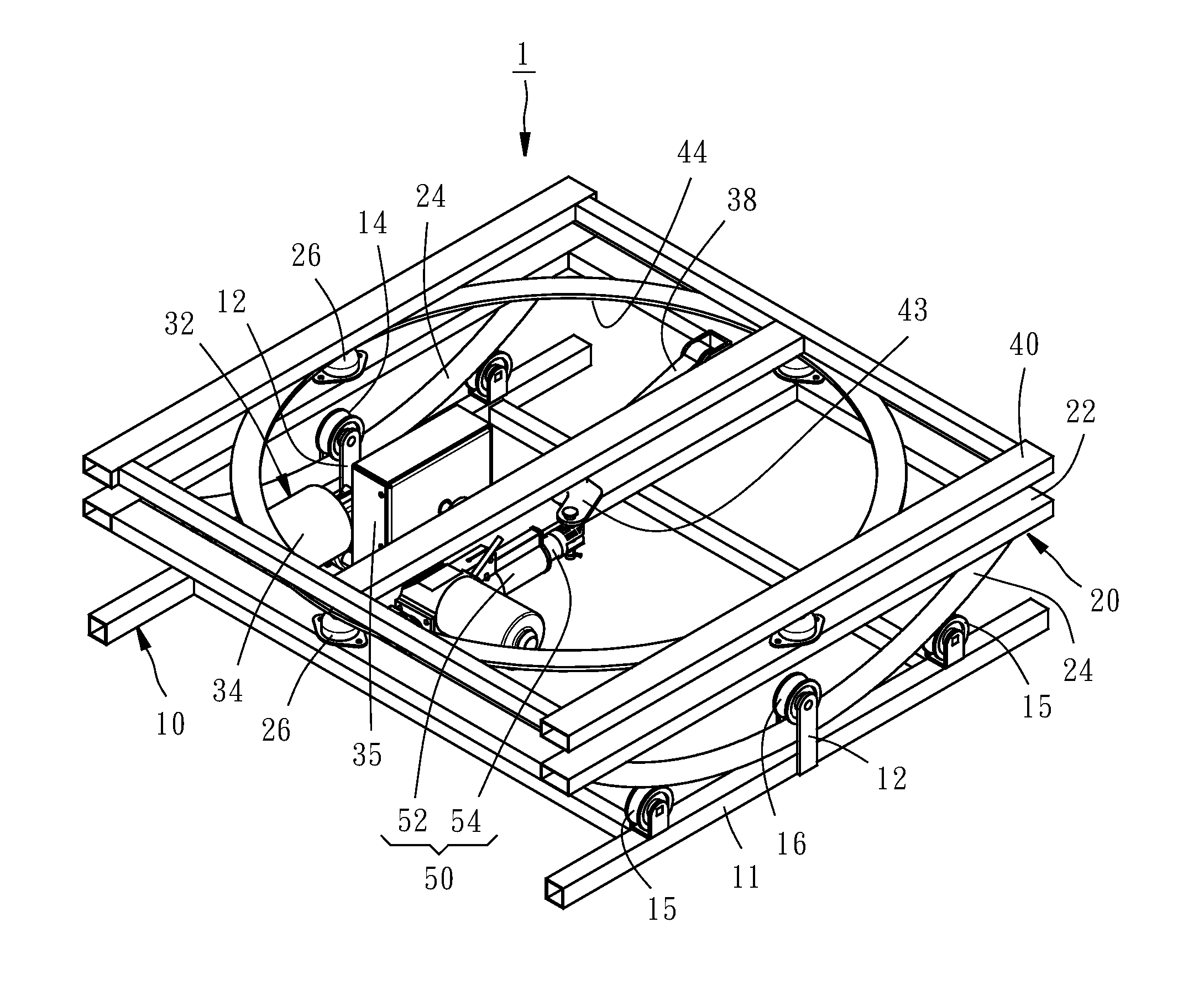
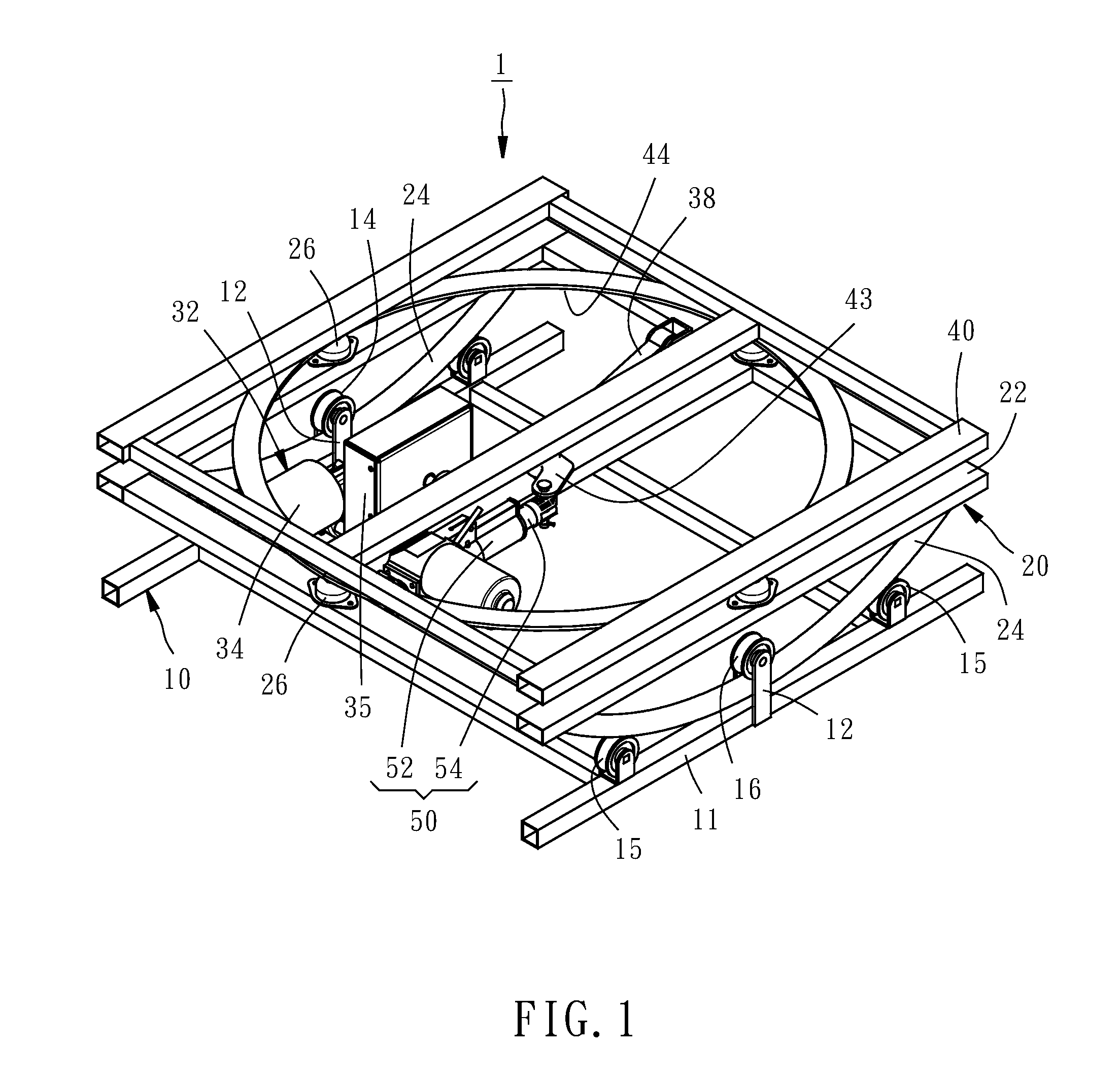
| Family ID: | 68056466 | ||||||||||
| Appl. No.: | 15/942189 | ||||||||||
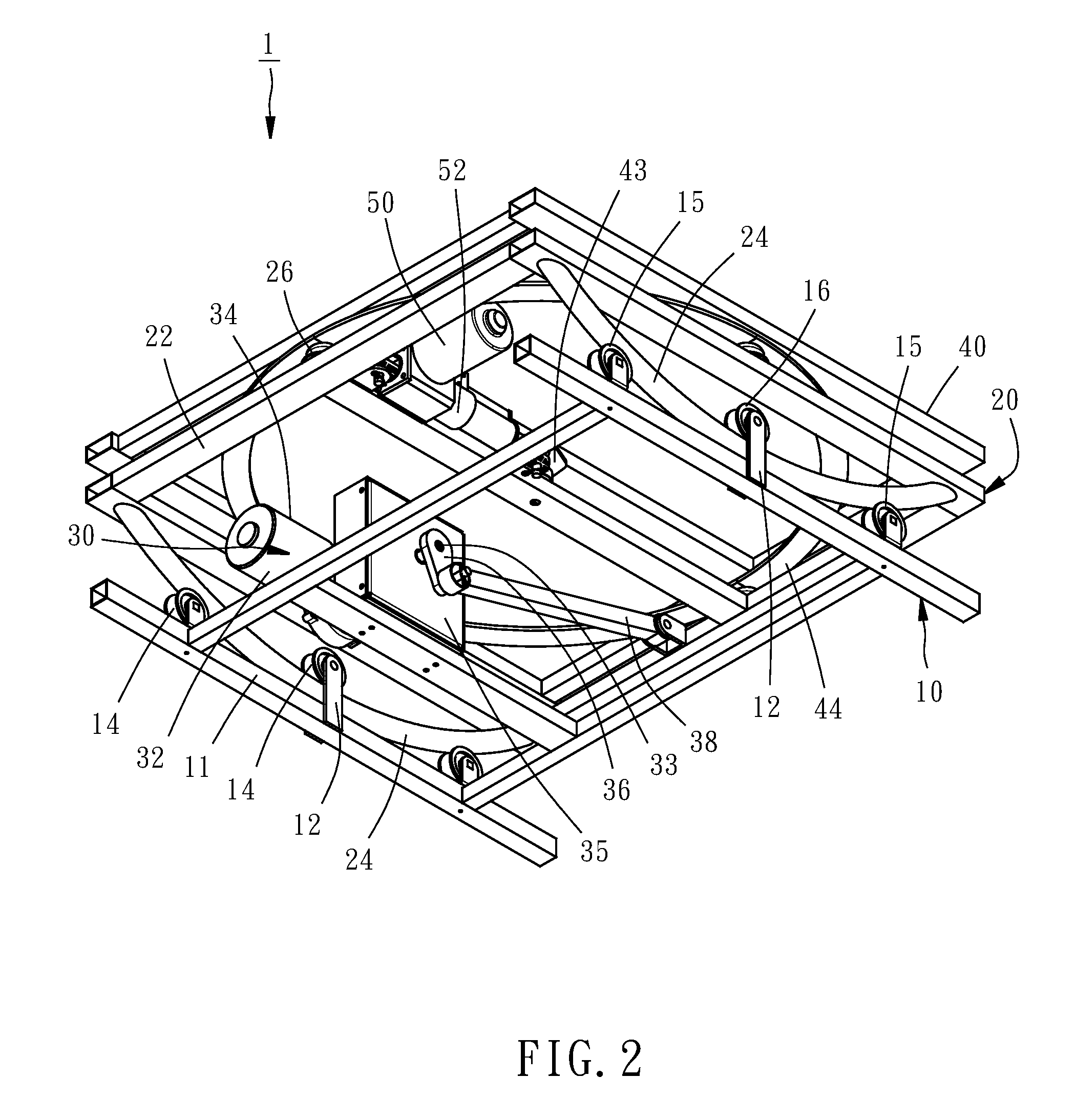
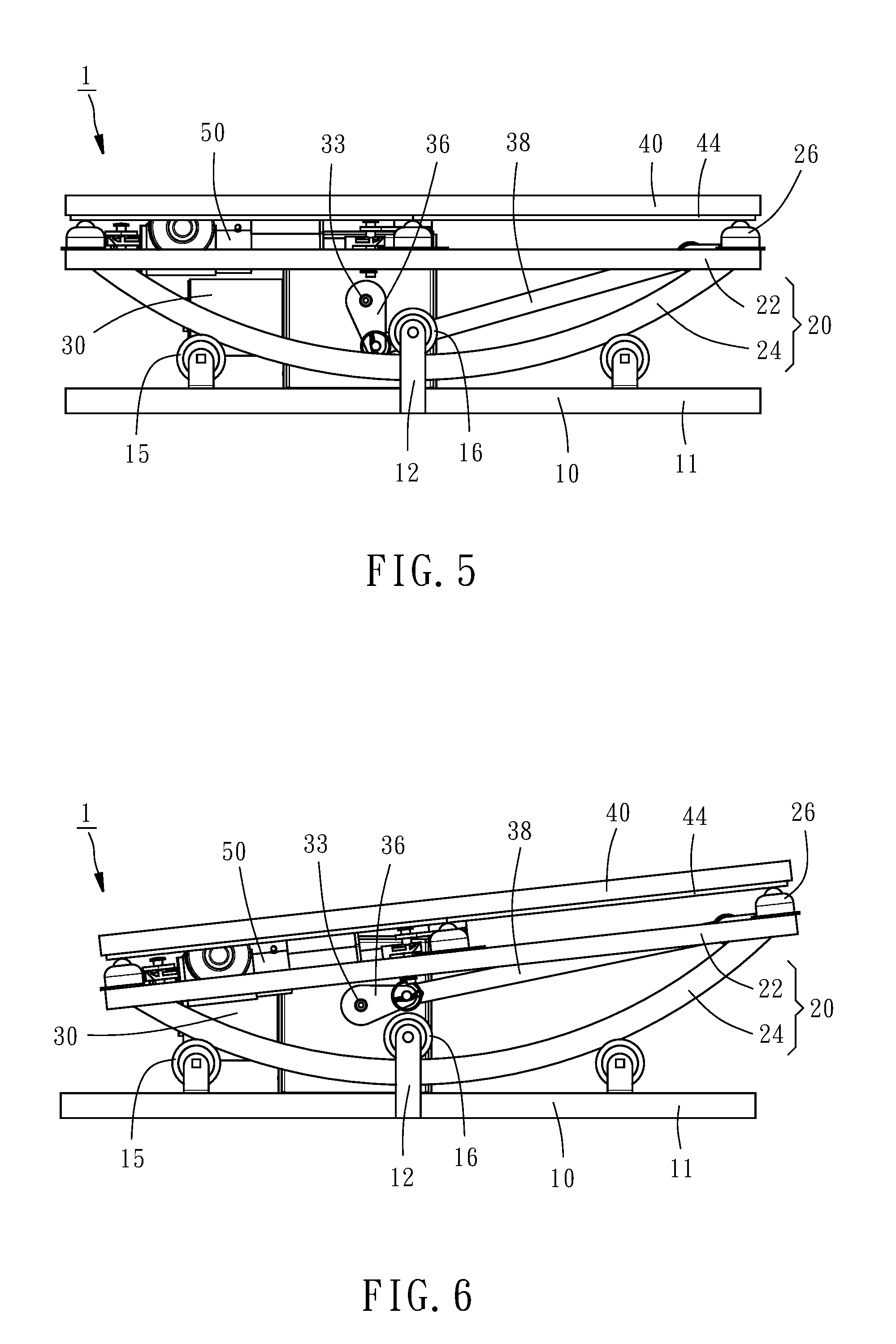
| Filed: | March 30, 2018 |
| Current U.S. Class: | 1/1 |
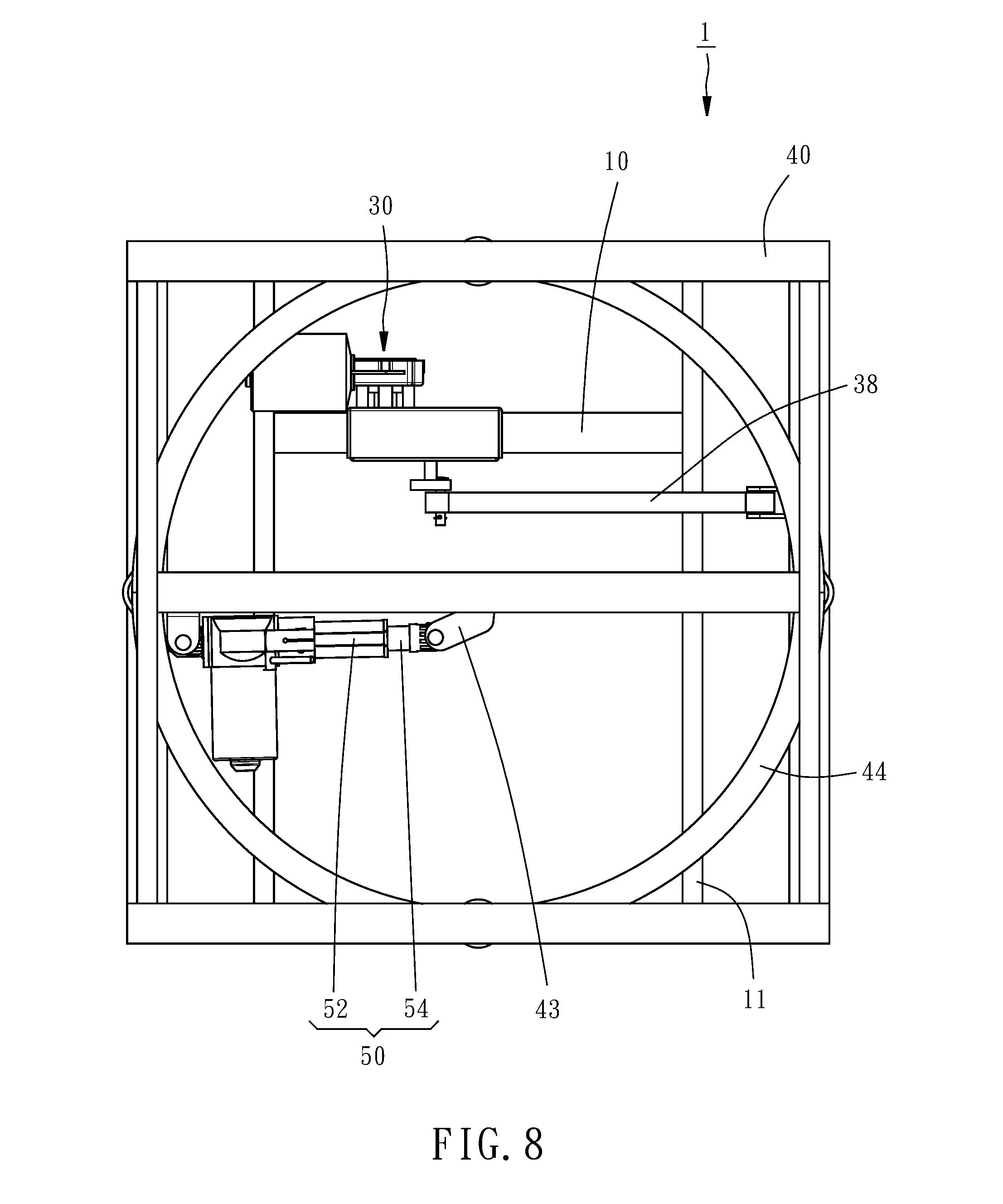
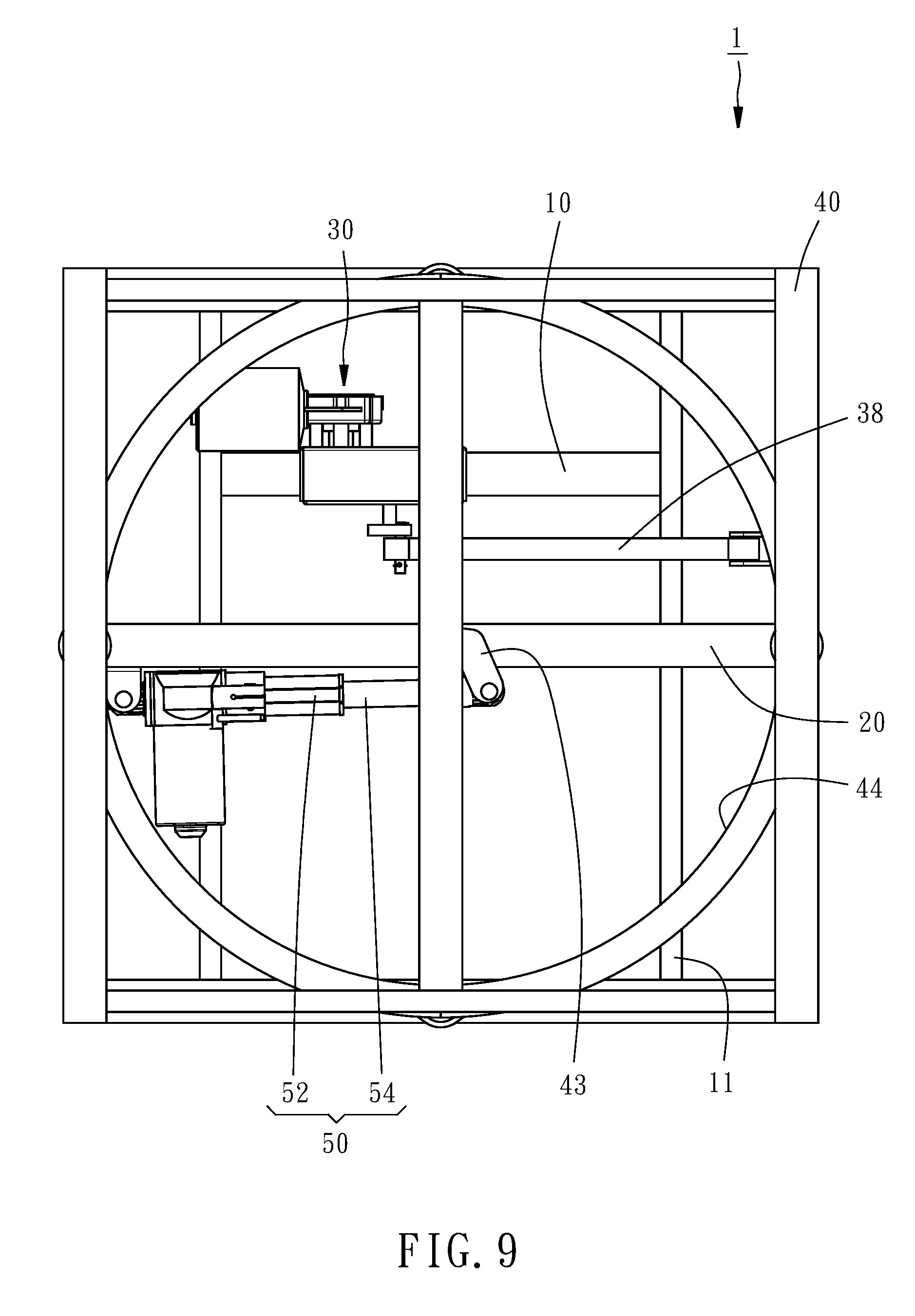
| Current CPC Class: | A47C 3/027 20130101; A47C 3/0251 20180801; A47C 7/002 20130101; A47C 3/0255 20130101; A47C 21/006 20130101 |
| International Class: | A47C 3/025 20060101 A47C003/025; A47C 7/00 20060101 A47C007/00; A47C 21/00 20060101 A47C021/00 |
Claims
1. A base seat for being used with a bed or a chair, the base seat comprising: a fixation base; a rocking mount disposed above the fixation base in a way that the rocking mount is reciprocatingly and inclinedly moveable relative to the fixation base; a drive device disposed between the fixation base and the rocking mount to drive the rocking mount to reciprocatingly and inclinedly move relative to the fixation base; and a swivel mount disposed above the rocking mount in a way that the swivel mount is rotatable relative to the rocking mount.
2. The base seat of claim 1, wherein the rocking mount comprises a pivot portion, and the swivel mount comprises a coupling portion coupled with the pivot portion of the rocking mount.
3. The base seat of claim 1, further comprising an actuator having two ends pivotally connected with the rocking mount and the swivel mount, respectively.
4. The base seat of claim 1, wherein the swivel mount comprises an abutment portion, and the rocking mount is disposed with at least one sliding contact member in contact with the abutment portion of the swivel mount; whereby the swivel mount is smoothly rotatable relative to the rocking mount.
5. The base seat of claim 1, wherein the rocking mount comprises an abutment portion, and the swivel mount is disposed with at least one sliding contact member in contact with the abutment portion of the rocking mount; whereby the swivel mount is smoothly rotatable relative to the rocking mount.
6. The base seat of claim 1, wherein the fixation base comprises a bottom portion and a plurality of rollers disposed above the bottom portion; the rocking mount comprises a bearing portion and an arc rail, which is located under the bearing portion and in contact with the rollers.
7. The base seat of claim 6, wherein the rollers comprise at least two lower rollers, which are located under the arc rail, and one upper roller located above the arc rail and between the two lower rollers.
8. The base seat of claim 7, wherein the fixation base comprises two supporting arms upwardly extending from the bottom portion of the fixation base; the upper roller is rotatably disposed between the two supporting arms, and the arc rail of the rocking mount extends through a space between the two supporting arms.
9. The base seat of claim 1, wherein the drive device comprises a power source, a crank and a link; the power source is disposed to the fixation base and provided with a power output shaft; the crank has an end connected with the power output shaft; the link has two ends pivotally connected with the crank and the rocking mount, respectively.
10. The base seat of claim 1, wherein the fixation base comprises a bottom portion and an arc rail disposed above the bottom portion; the rocking mount comprises a bearing portion and a plurality of rollers, which are located under the bearing portion and in contact with the arc rail.
11. The base seat of claim 10, wherein the rollers comprise at least two upper rollers, which are located above the arc rail, and one lower roller located under the arc rail and between the two upper rollers.
12. The base seat of claim 1, wherein the swivel mount is omitted.
Description
BACKGROUND OF THE INVENTION
1. Field of the Invention
[0001] The present invention relates generally to a furniture and more particularly, to a base seat adapted for being used with a bed or a chair.
2. Description of the Related Art
[0002] Conventional bedsteads and chairs have generally a stationary structure. With continuous improvement to people's living standards, more and more beds and chairs having various swing functions are developed and commercially available to provide more comfortable and relaxing user experience. However, such kinds of rocking chairs or swingable beds encountered many technical challenges. For example, as an article carrying body weight, a swingable design may be more complicated in structure and weak in structural strength than a stationary structural design, resulting in that not only the problem of low life span but also the problem of high operation noise caused by movements of elements need to be resolved. Further, the design of swing mode is also important. A swing mode that is not ergonomic may cause discomfort, such as dizziness, to user. Furthermore, the conventional rocking chairs or swingable beds usually provide a reciprocating swing motion in a single direction, inevitably resulting in that user may feel mental fatigue and even physical fatigue after using the conventional rocking chair or swingable bed for a certain period of time.
SUMMARY OF THE INVENTION
[0003] The present invention has been accomplished in view of the above-noted circumstances. It is an objective of the present invention to provide a base seat for being used with a bed or chair, which has an ergonomic swing function to make a user feel more comfortable and relaxing.
[0004] Another objective of the present invention is to provide a base seat for being used with a bed or a chair, which has a firm and stable structure, a long life span, and a low noise in operation.
[0005] Still another objective of the present invention is to provide a base seat for being used with a bed or a chair, which can adjust its swinging direction so as to avoid user's metal or physical fatigue and to provide diverse and flexible user experience.
[0006] To attain the above objectives, the present invention provides a base seat, which is adapted for being used with a bed or a chair and comprises a fixation base, a rocking mount, a drive device, and a swivel mount. The rocking mount is disposed above the fixation base and reciprocatingly and inclinedly moveable relative to the fixation base. The drive device is disposed between the fixation base and the rocking mount to drive the rocking mount to reciprocatingly and inclinedly move relative to the fixation base. The swivel mount is disposed above the rocking mount and rotatable relative to the rocking mount. As a result, the base seat for being used with a bed or a chair has an ergonomic swing function, a firm and stable structure, and a long life span, and can be operated under a low noise. The swinging direction of the base seat of the present invention can be adjusted during operation so as to avoid user's metal or physical fatigue and to provide diverse and flexible user experience.
BRIEF DESCRIPTION OF THE DRAWINGS
[0007] The present invention will become more fully understood from the detailed description given herein below and the accompanying drawings which are given by way of illustration only, and thus are not limitative of the present invention, and wherein:
[0008] FIG. 1 is a perspective view of a base seat according to a first embodiment of the present invention;
[0009] FIG. 2 is another perspective view of the base seat according to the first embodiment of the present invention;
[0010] FIG. 3 is an exploded view of the base seat according to the first embodiment of the present invention;
[0011] FIG. 4 is another exploded view of the base seat according to the first embodiment of the present invention;
[0012] FIG. 5 is a front view of the base seat according to the first embodiment of the present invention;
[0013] FIGS. 6 and 7 are front views showing the base seat is operated to swing;
[0014] FIG. 8 is a top view of the base seat according to the first embodiment of the present invention;
[0015] FIG. 9 is a top view showing the base seat is operated to rotate;
[0016] FIG. 10 is a perspective view of a base seat according to a second embodiment of the present invention;
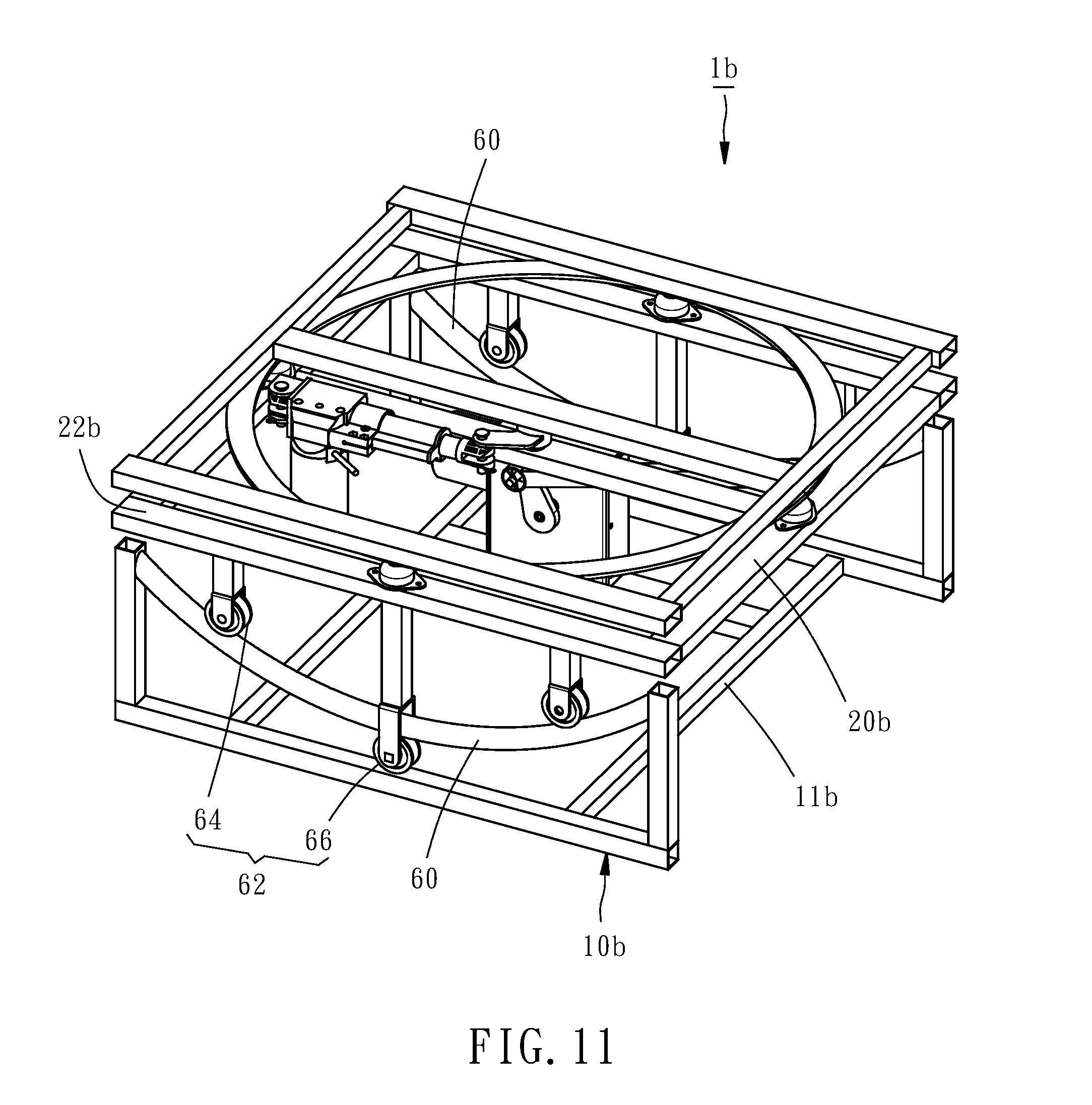
[0017] FIG. 11 is a perspective view of a base seat according to a third embodiment of the present invention; and
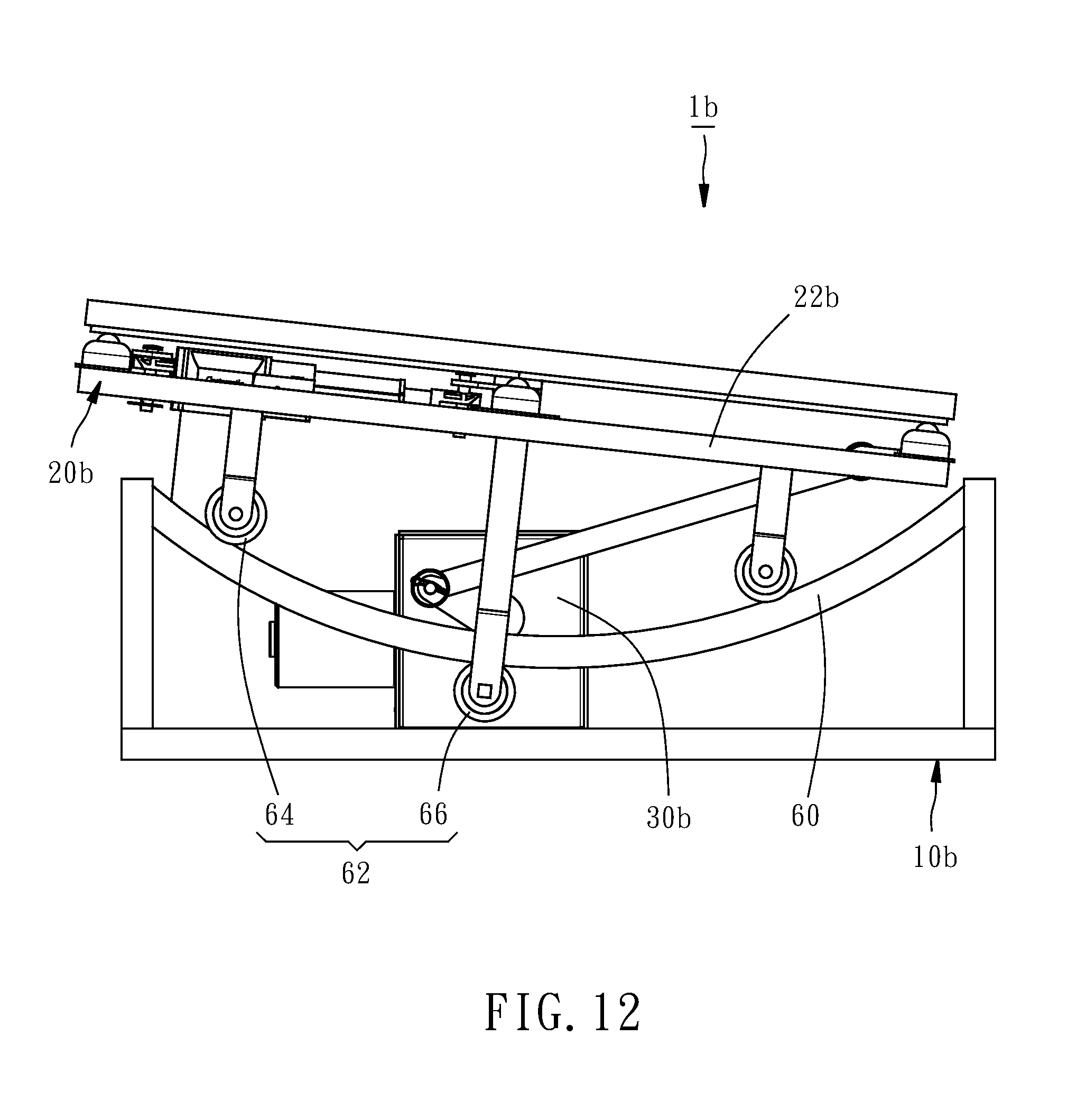
[0018] FIG. 12 is a front view of the base seat according to the third embodiment of the present invention, showing that the base seat is operated to swing.
DETAILED DESCRIPTION OF THE INVENTION
[0019] FIGS. 1-4 show a base seat 1 for providing rocking and swing motion in various directions for a bed (not shown) or a chair (not shown) fixedly positioned thereon. The base seat 1 comprises a fixation base 10, a rocking mount 20, a drive device 30, a swivel mount 40, and an actuator 50.
[0020] The fixation base 10 includes a bottom portion 11 and a plurality of rollers 14. The bottom portion 11 is formed by a rectangular frame for being placed on a ground. Four supporting arms 12 extend upwardly from the bottom portion 11 and are arranged pair by pair. The rollers 14 are rotatably disposed above the bottom portion 11 and arranged in two parallel rows each including two lower rollers 15 and one upper roller 16. Each upper roller 16 is rotatably disposed between paired two supporting arms 12 in a way that the upper roller 16 is located higher than the lower rollers 15 and the upper roller 16 is located between the two lower rollers 15 in a same row. In another embodiment, the shape of the bottom portion 11 and the number, arrangement and installation of the rollers 14 may be modified.
[0021] The rocking mount 20 is disposed above the fixation base 10 and reciprocatingly and inclinedly moveable relative to the fixation base 10. The rocking mount 20 includes a bearing portion 22, a pivot portion 23 and two arc rails 24. The bearing portion 22 is formed by a square frame, the pivot portion 23 is disposed at about a center of the bearing portion 22, and the arc rails 24 are disposed under two lateral sides of the bearing portion 22 and in contact with the rollers 14. The arc rail 24 has a shape of a sector of a circle and protrudes downwardly. The arc rail 24 is formed by a round tube such that the transverse cross-section of the arc rail 24 shows a circular profile and the arc rail 24 is linearly in contact with the rollers 14. Each arc rail 24 extends through a space between one pared supporting arms 12, such that the rocking mount 20 can be stably installed with the fixation base 10 without escaping from the fixation base 10. With aforesaid design, the rocking mount 20 is reciprocatingly and inclinedly moveable relative to the fixation base 10, as shown in FIGS. 6 and 7, i.e. swingable back and forth relative to the fixation base 10 like a pendulum having a pivot point suspended above the rocking mount 20 that serves as a bob and a rod connected between the pivot point and the rocking mount 20, thereby having stable structure and being operated with low noise. Further, four sliding contact members 26 are mounted on the bearing portion 22 of the rocking mount 20 for contacting the swivel mount 40. In this embodiment, the sliding contact member 26 is realized as a universal ball member. In another embodiment, the structure of the rocking mount 20 may be modified as long as the rocking mount 20 is capable of reciprocatingly and inclinedly moving relative to the fixation base 10.
[0022] The drive device 30 is disposed between the fixation base 10 and the rocking mount 20 and capable of driving the rocking mount 20 to reciprocatingly and inclinedly move relative to the fixation base 10. For the drive device 30, various designs may be used. In this embodiment, the drive device 30 comprises a power source 32, a crank 36 and a link 38. The power source 32 is disposed on the fixation base 10 and provided with a power output shaft 33. Specifically, the power source 32 is composed of a motor 34 and a reduction gearbox 35. The crank 36 has an end connected with the power output shaft 33. Two ends of the link 38 are pivotally connected with the crank 36 and the rocking mount 20. As such, when the motor 34 is operated to drive the output shaft 33 to rotate, the rocking mount 20 is driven by the link 38 through the crank 36 to reciprocatingly and inclinedly move relative to the fixation base 10, as shown in FIGS. 5-7. The drive device 30 provided in this embodiment is structurally reliable and can be operated with low noise.
[0023] The swivel mount 40 is rotatably disposed above the rocking mount 20. In this embodiment, the swivel mount 40 is formed by a square frame and provided at a center thereof with a coupling portion 42 coupled with the pivot portion 23 of the rocking mount 20 in a way that the swivel mount 40 is rotatable about the coupling portion 42, which serves as a pivotal axis of the swivel mount 40, relative to the rocking mount 20. An extension portion 43 extends laterally from the coupling portion 42 and has a distal end pivotally connected with an end of the actuator 50. The actuator 50 has the other end pivotally connected with the bearing portion 22 of the rocking mount 20. In this embodiment, the actuator 50 is an electric actuator cylinder having a cylinder body 52 and a slidable rod 54 capable of extending out of and retracting into the cylinder body 52, such that the total length of the actuator 50 is changeable dynamically and adjustably. The cylinder body 52 is pivotally connected with the bearing portion 22 of the rocking mount 20, and the slidable rod 54 is pivotally connected with the extension portion 43. By means of continual retracting and extending motion of the slidable rod 54 relative to the cylinder body 52, the total length of the actuator 50 is continuously changed. Further, the swivel mount 40 is provided with a circular ring-shaped abutment portion 44 in contact with the sliding contact members 26, such that the swivel mount 40 can be smoothly rotated relative to the rocking mount 20. In this way, when the actuator 50 extends its length, the swivel mount 40 can be driven to rotate relative to the rocking mount 20 at an angle of 90 degrees, as shown in FIGS. 8 and 9. In another embodiment, the coupling structures of the swivel mount 40 and the rocking mount 20 may be modified as long as the swivel mount 40 can be rotated relive to the rocking mount 20. Furthermore, the swivel mount 40 may be configured by a circular disc, such that the bottom surface of the circular disc can serve as the abutment portion 44 directly. Moreover, it is only required that the two ends of the actuator 50 are pivotally connected with the rocking mount 20 and the swivel mount 40, respectively. In other words, the pivotally connecting locations between the actuator 50 and the rocking mount 20 and between the actuator 50 and the swivel mount 40 are not limited to the locations disclosed in this embodiment.
[0024] With the above-mentioned structural design, when a bed or a chair is installed on the base seat 1 of the present invention, and more specifically when the bed or the chair is fixedly mounted on the swivel mount 40, the drive device 30 can drive the bed or the chair to perform a swing motion in a given direction, such as a back-and-forth direction or a left-and-right direction. Such wing motion is like a hammock or pendulum motion, which is an ergonomic, relaxing and comfortable motion. Besides, because there are only relative rotational or rolling movements among the elements of the base seat 1 without the relative displacements thereamong, the base seat 1 can be operated in a very lower noise. Further, by means of rotating the swivel mount 40 relative to the rocking mount 20 through the operation of the actuator 50, the swinging direction of the bed or the chair can be adjusted from an existing direction to another desired direction, i.e. from a left-and-right direction to a back-and-forth direction or any arbitrary direction for example. With this direction adjustable function, the mental fatigue or physical fatigue of a user caused by the swing motion in a single, monotone direction can be avoided, and the user can adjust the swing mode according to personal preference. That is, the base seat 1 of the present invention can provide more diverse and flexible user experience, having great market potential.
[0025] Based on the technical features of the present invention, various modifications to the structure of the base seat 1 of the present invention may be made. For example, the installation locations of the sliding contact members 26 and the abutment portion 44 can be exchanged, i.e. the sliding contact members 26 are provided at the bottom of the swivel mount and the abutment portion is provided at the top of the rocking mount. Further, the sliding contact member 26 can be realized by a bearing, such as a ring bearing, and one or more sliding contact members can be used in the base seat 1, i.e. at least one sliding contact member is sufficient. The number of the arc rails 24 of the rocking mount 20 is also not limited to the number of the previous embodiment. That is, the rocking mount 20 may be equipped with one or more arc rails 24. For example, FIG. 10 shows a base seat la according to a second embodiment of the present invention, which has a structure basically same as the base seat 1 of the first embodiment, except that the rocking mount 20a has only one arc rail 24a, and a single row of rollers 14a is provided above the bottom portion 11a of the fixation base 10a in a way that the rollers 14a are in contact with the arc rail 24a. In this embodiment, the rollers 14a in a single row include two lower rollers 15a and one upper roller 16a, and the arc rail 24a is formed by a rectangular tube having a rectangular transverse cross-section, such that the arc rail 24a is in contact with the rollers 14a in a linear contact manner. In this way, the rocking mount 20a can also be stably and firmly installed with the fixation base 10a.
[0026] In another aspect, various modifications to the structures of the fixation base and the rocking mount may be made. FIG. 11 shows a base seat 1b according to a third embodiment of the present invention, which has a structure basically same as the base seat 1 of the first embodiment, except that there is no roller disposed to the fixation base 10b and two arc rails 60 is disposed above the bottom portion 11b, and there is no arc rail disposed to the rocking mount 20b and two rows of rollers 62 are disposed under the bearing portion 22b and in contact with the two arc rails 60. The rollers 62 arranged on each row include two upper rollers 64 located above one arc rail 60, and a lower roller 66 located under the arc rail 60 and between the two upper rollers 64. As such, the drive device 30b can drive the rocking mount 20b to reciprocatingly and inclinedly move relative to the fixation base 10b, as show in FIG. 12.
[0027] In another embodiment, the actuator 50 may be omitted. In this case, user may manually adjust the rotational angle of the swivel mount 40 relative to the rocking mount 20. In still another embodiment, for simplifying the structure of the base seat of the present invention, the swivel mount may be even omitted. In this situation, when installing the bed or chair to the rocking mount 20, the user may set them at a specific installation angle according to the user's preference angle of swing.
[0028] To sum up, the base seat of the present invention, which is adapted for supporting a bed or a chair thereon, provides swing motion in various directions and in fulfillment with ergonomics so as to avoid user's metal or physical fatigue and to provide diverse and flexible user experience, making the user feel more relaxing and comfortable. Further, the base seat has a firm and stable structure and a long life span, and can be operated under a low noise thanks to the design of associated rail and roller as well as the design of associated sliding contact member and abutment portion.
[0029] The invention being thus described, it will be obvious that the same may be varied in many ways. Such variations are not to be regarded as a departure from the spirit and scope of the invention, and all such modifications as would be obvious to one skilled in the art are intended to be included within the scope of the following claims.
* * * * *
D00000
D00001
D00002
D00003
D00004
D00005
D00006
D00007
D00008
D00009
D00010
D00011
XML
uspto.report is an independent third-party trademark research tool that is not affiliated, endorsed, or sponsored by the United States Patent and Trademark Office (USPTO) or any other governmental organization. The information provided by uspto.report is based on publicly available data at the time of writing and is intended for informational purposes only.
While we strive to provide accurate and up-to-date information, we do not guarantee the accuracy, completeness, reliability, or suitability of the information displayed on this site. The use of this site is at your own risk. Any reliance you place on such information is therefore strictly at your own risk.
All official trademark data, including owner information, should be verified by visiting the official USPTO website at www.uspto.gov. This site is not intended to replace professional legal advice and should not be used as a substitute for consulting with a legal professional who is knowledgeable about trademark law.