Top Panel Height Adjustable Furniture
YAMAMOTO; Takayuki ; et al.
U.S. patent application number 16/316607 was filed with the patent office on 2019-10-03 for top panel height adjustable furniture. The applicant listed for this patent is OKAMURA CORPORATION. Invention is credited to Noriya MIKAMI, Sumio NISHIMURA, Masaharu SUGA, Makoto TAKAHASHI, Takayuki YAMAMOTO.
| Application Number | 20190298055 16/316607 |
| Document ID | / |
| Family ID | 60953057 |
| Filed Date | 2019-10-03 |


View All Diagrams
| United States Patent Application | 20190298055 |
| Kind Code | A1 |
| YAMAMOTO; Takayuki ; et al. | October 3, 2019 |
TOP PANEL HEIGHT ADJUSTABLE FURNITURE
Abstract
Top panel height adjustable furniture (1) includes a top panel (2) that has an upper surface (3) and a lower surface (4); a support body (5) that is connected to the top panel (2) and is capable of extending or contracting in a panel thickness direction of the top panel (2); a sensor (11) that detects contact of a user on the upper surface (3) side of the top panel (2) and contact of the user on the lower surface (4) side of the top panel (2); and a control unit that controls, based on a detection result of the sensor (11), an extending/contracting operation of the support body (5) such that the support body (5) contracts when it is detected that the user has made contact with the top panel (2) on the upper surface (3) side of the top panel (2) and that the support body (5) extends when it is detected that the user has made contact with the top panel (2) on the lower surface (4) side of the top panel (2).
| Inventors: | YAMAMOTO; Takayuki; (Yokohama-shi, JP) ; TAKAHASHI; Makoto; (Yokohama-shi, JP) ; SUGA; Masaharu; (Yokohama-shi, JP) ; NISHIMURA; Sumio; (Yokohama-shi, JP) ; MIKAMI; Noriya; (Yokohama-shi, JP) | ||||||||||
| Applicant: |
|
||||||||||
|---|---|---|---|---|---|---|---|---|---|---|---|
| Family ID: | 60953057 | ||||||||||
| Appl. No.: | 16/316607 | ||||||||||
| Filed: | July 12, 2017 | ||||||||||
| PCT Filed: | July 12, 2017 | ||||||||||
| PCT NO: | PCT/JP2017/025388 | ||||||||||
| 371 Date: | January 9, 2019 |
| Current U.S. Class: | 1/1 |
| Current CPC Class: | A47B 9/20 20130101; A47B 2200/0056 20130101; A47B 2200/0062 20130101; A47B 9/00 20130101; A47B 2200/0052 20130101 |
| International Class: | A47B 9/20 20060101 A47B009/20 |
Foreign Application Data
| Date | Code | Application Number |
|---|---|---|
| Jul 12, 2016 | JP | 2016-137667 |
| Jul 12, 2016 | JP | 2016-137668 |
Claims
1. Top panel height adjustable furniture, comprising: a top panel that has an upper surface and a lower surface; a support body that supports the top panel such that the top panel is vertically movable; a sensor that detects contact of a user on the upper surface side of the top panel and contact of the user on the lower surface side of the top panel; and a control unit that controls, based on a detection result of the sensor, a supporting position of the top panel such that the top panel is moved downward when it is detected that the user has made contact with the top panel on the upper surface side of the top panel and the top panel is moved upward when it is detected that the user has made contact with the top panel on the lower surface side of the top panel.
2. The top panel height adjustable furniture according to claim 1, wherein the sensor is installed in the top panel.
3. The top panel height adjustable furniture according to claim 1, wherein the sensor is installed in a part other than the top panel of the top panel height adjustable furniture.
4. The top panel height adjustable furniture according to claim 1, wherein the sensor has: a first sensor which is installed on the upper surface of the top panel; and a second sensor which is installed on the lower surface of the top panel, and wherein the control unit causes the top panel to move downward while the user is in contact with the first sensor and causes the top panel to move upward while the user is in contact with the second sensor.
5. The top panel height adjustable furniture according to claim 4, wherein the first sensor and the second sensor are disposed such that the first sensor and the second sensor overlap each other when seen from the upper surface toward the lower surface.
6. The top panel height adjustable furniture according to claim 4, wherein an outer surface of the first sensor is positioned on substantially the same surface as the upper surface of the top panel.
7. The top panel height adjustable furniture according to claim 4, wherein an outer surface of the second sensor is positioned on substantially the same surface as the lower surface of the top panel.
8. The top panel height adjustable furniture according to claim 1, wherein the sensor has a contact sensor which detects presence or absence of contact of the user with respect to the top panel, the contact sensor being disposed in a front end portion of the top panel and extending along a width direction of the top panel.
9. The top panel height adjustable furniture according to claim 1, wherein the sensor has a distortion sensor which detects distortion of the top panel caused by contact of the user with respect to the top panel, and wherein the control unit causes the top panel to move downward while the distortion sensor is detecting distortion generated in the top panel by the user pushing the upper surface of the top panel to the lower surface side, and causes the top panel to move upward while the distortion sensor is detecting distortion generated in the top panel by the user pushing the lower surface of the top panel to the upper surface side.
10. The top panel height adjustable furniture according to claim 1, wherein the sensor identifies a posture of a user's hand which comes into contact with the top panel, and wherein the control unit selects either one of raising and lowering of the top panel based on the posture identified by the sensor.
11. The top panel height adjustable furniture according to claim 10, wherein a plurality of sensors are provided on each of the upper surface and the lower surface of the top panel, and wherein the control unit recognizes the posture of the user's hand which comes into contact with the top panel, based on a combination of detection states of the plurality of sensors.
12. The top panel height adjustable furniture according to claim 10, wherein the sensor individually detects a contact area of the user's hand with the upper surface of the top panel and a contact area of the user's hand with the lower surface of the top panel, and wherein the control unit selects either one of raising and lowering of the top panel based on a difference between the contact area of the user's hand with the upper surface of the top panel and the contact area of the user's hand with the lower surface of the top panel.
13. The top panel height adjustable furniture according to claim 1, wherein the sensor detects a contact area of the user's hand with the upper surface or the lower surface of the top panel, and wherein the control unit determines a raising/lowering speed of the top panel based on a size of the contact area detected by the sensor.
14. The top panel height adjustable furniture according to claim 1, wherein the sensor detects a magnitude of an external force applied to the top panel, and wherein the control unit determines a raising/lowering speed of the top panel based on the magnitude of the external force detected by the sensor.
15. The top panel height adjustable furniture according to claim 10, wherein the sensor has: a first distal sensor which is installed on the upper surface of the top panel; a first proximal sensor which is installed at a position closer to a front end portion of the top panel than the first distal sensor on the upper surface of the top panel; a second distal sensor which is installed on the lower surface of the top panel; and a second proximal sensor which is installed at a position closer to the front end portion of the top panel than the second distal sensor on the lower surface of the top panel, and wherein the control unit controls the supporting position of the top panel such that the top panel is moved downward when contact of the user is detected by the first distal sensor, the first proximal sensor, and the second proximal sensor, and the top panel is moved upward when contact of the user is detected by the first proximal sensor, the second distal sensor, and the second proximal sensor.
16. The top panel height adjustable furniture according to claim 1, wherein the sensor has: a first sensor which receives an input for lowering the top panel; a second sensor which receives an input for raising the top panel; and a receiving portion which receives an input of permission or inhibition of raising or lowering of the top panel, and wherein the control unit controls the supporting position of the top panel based on detection results of the first sensor and the second sensor when permission for raising or lowering of the top panel is input to the receiving portion.
17. The top panel height adjustable furniture according to claim 16, wherein the receiving portion is installed in the support body.
18. The top panel height adjustable furniture according to claim 16, wherein the receiving portion is installed in the top panel.
19. The top panel height adjustable furniture according to claim 16, wherein permission for raising or lowering of the top panel is input to the receiving portion when an input to the first sensor and an input to the second sensor simultaneously continue for a predetermined period of time or longer.
Description
TECHNICAL FIELD
[0001] The present invention relates to top panel height adjustable furniture.
[0002] Priority is claimed on Japanese Patent Application No. 2016-137667, filed Jul. 12, 2016, and Japanese Patent Application No. 2016-137668, filed Jul. 12, 2016, the contents of which are incorporated herein by reference.
BACKGROUND ART
[0003] In the related art, furniture including a top panel capable of being raised and lowered is known.
[0004] As a technology of raising and lowering a top panel of furniture, for example, a method of using a gas spring and a method of using a gear (Patent Documents 1 and 2) are known.
[0005] In the methods disclosed in Patent Documents 1 and 2, since the structure is simple, the costs can be kept low. However, in the methods disclosed in Patent Documents 1 and 2, it may be difficult for a user lacking in strength to perform an operation, or a user may be forced to adopt an unnatural posture to raise or lower the top panel depending on the height of the top panel.
[0006] In order to improve operability when a top panel is raised and lowered, a technology of raising and lowering the top panel using an electric drive unit is known (Patent Documents 3, 4, and 5). In the technologies disclosed in Patent Documents 3, 4, and 5, a user can perform a raising/lowering operation of the top panel using an operation unit such as a switch installed in the vicinity of the top panel.
DOCUMENT OF RELATED ART
Patent Document
[0007] Patent Document 1: Japanese Patent No. 3371959
[0008] Patent Document 2: Japanese Patent No. 3391285
[0009] Patent Document 3: Japanese Utility Model (Registered) Publication No. 3164739
[0010] Patent Document 4: Japanese Unexamined Patent Application, First Publication No. 2014-113505
[0011] Patent Document 5: Japanese Unexamined Patent Application, First Publication No. 2014-140753
SUMMARY OF INVENTION
Technical Problem
[0012] In technologies disclosed in Patent Documents 3, 4, and 5, a top panel is raised or lowered by pushing a switch. Therefore, an operation for raising or lowering the top panel is not intuitively performed. In addition, when the switch is disposed in a large-sized top panel, a user raising or lowering the top panel needs to move to a position of the switch to operate the switch. Therefore, it takes time and effort to perform this operation. In addition, if the switch is erroneously pushed, the top panel is moved unintentionally.
[0013] The present invention has been made in consideration of the foregoing circumstances, and an object thereof is to provide top panel height adjustable furniture in which a raising/lowering operation of a top panel can be intuitively and easily performed.
[0014] In addition, the present invention has been made in consideration of the foregoing circumstances, and another object thereof is to provide top panel height adjustable furniture in which an erroneous raising/lowering operation of the top panel is hardly caused.
Solution to Problem
[0015] Top panel height adjustable furniture according to an aspect of the present invention includes a top panel that has an upper surface and a lower surface; a support body that supports the top panel such that the top panel is vertically movable; a sensor that detects contact of a user on the upper surface side of the top panel and contact of the user on the lower surface side of the top panel, and is installed in the top panel; and a control unit that controls, based on a detection result of the sensor, a supporting position of the top panel such that the top panel is moved downward when it is detected that the user has made contact with the top panel on the upper surface side of the top panel and the top panel is moved upward when it is detected that the user has made contact with the top panel on the lower surface side of the top panel.
[0016] In such a configuration, the control unit can cause the top panel to be raised or lowered in accordance with a gesture of the user bringing his/her hand into contact with the top panel to raise or lower the top panel. Therefore, the user can intuitively perform a raising/lowering operation of the top panel, and the top panel can be easily raised or lowered.
[0017] The sensor may be installed in the top panel.
[0018] In this case, it is possible to more reliably detect contact of the user with the top panel.
[0019] The sensor may be installed in a part other than the top panel of the top panel height adjustable furniture.
[0020] In this case, the entire area of the upper surface of the top panel can be used as a work surface. Therefore, usability of the furniture becomes favorable.
[0021] The sensor may have a first sensor which is installed on the upper surface of the top panel and a second sensor which is installed on the lower surface of the top panel. The control unit may cause the top panel to move downward while the user is in contact with the first sensor and may cause the top panel to move upward while the user is in contact with the second sensor.
[0022] In this case, when the user lowers the top panel, the user brings his/her hand into contact with the upper surface of the top panel. Accordingly, the top panel is lowered based on the contact of the hand with the first sensor installed on the upper surface of the top panel. On the contrary, when the user raises the top panel, the user brings his/her hand into contact with the lower surface of the top panel. Accordingly, the top panel is raised based on the contact of the hand with the second sensor installed on the lower surface of the top panel. Accordingly, the top panel can be raised or lowered simply by the user touching the top panel in a natural gesture for raising or lowering the top panel.
[0023] The first sensor and the second sensor may be disposed such that the first sensor and the second sensor overlap each other when seen from the upper surface toward the lower surface.
[0024] In this case, when seen in a vertical direction of the top panel (height direction), a part of the top panel with which the user brings his/her hand into contact to raise the top panel and a part of the top panel with which the user brings his/her hand into contact to lower the top panel coincide with each other. As a result, it is easy for the user to know where to bring his/her hand into contact with to raise or lower the top panel.
[0025] An outer surface of the first sensor may be positioned on substantially the same surface as the upper surface of the top panel.
[0026] In this case, there is no unnecessary irregularity on the upper surface of the top panel. Therefore, the top panel has excellent design.
[0027] An outer surface of the second sensor may be positioned on substantially the same surface as the lower surface of the top panel.
[0028] In this case, a foot, baggage, or the like of the user is unlikely to be caught by the lower surface of the top panel.
[0029] The sensor may have a contact sensor which detects the presence or absence of contact of the user with respect to the top panel, the contact sensor being disposed in a front end portion of the top panel and extending along a width direction of the top panel.
[0030] In this case, the user can perform a raising/lowering operation of the top panel in a natural posture regardless of his/her physique.
[0031] The sensor may have a distortion sensor which detects distortion of the top panel caused by contact of the user with respect to the top panel. The control unit may cause the top panel to move downward while the distortion sensor is detecting distortion generated in the top panel by the user pushing the upper surface of the top panel to the lower surface side, and may cause the top panel to move upward while the distortion sensor is detecting distortion generated in the top panel by the user pushing the lower surface of the top panel to the upper surface side.
[0032] In this case, the position at which the distortion sensor can be disposed is not particularly limited and need only be a position at which distortion generated in the top panel can be detected when the user intends to raise or lower the top panel. Therefore, even if the distortion sensor is disposed at a position where the user cannot touch the distortion sensor with his/her hand, a gesture of the user for raising or lowering the top panel can be recognized.
[0033] The sensor may identify a posture of a user's hand which comes into contact with the top panel. The control unit may select either one of raising and lowering of the top panel based on the posture identified by the sensor.
[0034] In this case, a raising/lowering control direction of the top panel by the control unit is determined in consideration of the posture of the hand, in a gesture of the user bringing the hand into contact with the top panel to move the top panel. Therefore, the top panel can be raised or lowered by an intuitive operation.
[0035] A plurality of sensors may be provided on each of the upper surface and the lower surface of the top panel. The control unit may recognize the posture of the user's hand which comes into contact with the top panel, based on a combination of detection states of the plurality of sensors.
[0036] In this case, the raising/lowering control direction of the top panel by the control unit is determined in consideration of a combination of the detection states of the plurality of sensors, in a gesture of the user bringing the hand into contact with the top panel to move the top panel. Therefore, the top panel can be raised or lowered by an intuitive operation.
[0037] The sensor may individually detect a contact area of the user's hand with the upper surface of the top panel and a contact area of the user's hand with the lower surface of the top panel. The control unit may select either one of raising and lowering of the top panel based on a difference between the contact area of the user's hand with the upper surface of the top panel and the contact area of the user's hand with the lower surface of the top panel.
[0038] In this case, the raising/lowering control direction of the top panel by the control unit is determined in consideration of the contact area of the user's hand, in a gesture of the user bringing the hand into contact with the top panel to move the top panel. Therefore, the top panel can be raised or lowered by an intuitive operation.
[0039] The sensor may detect a contact area of the user's hand with the upper surface or the lower surface of the top panel. The control unit may determine a raising/lowering speed of the top panel based on a size of the contact area detected by the sensor.
[0040] In this case, it is possible to automatically switch between a prompt raising/lowering operation of the top panel and fine adjustment of the height of the top panel by reflecting an intended raising/lowering speed of the top panel by the user.
[0041] The sensor may detect a magnitude of an external force applied to the top panel. The control unit may determine a raising/lowering speed of the top panel based on the magnitude of the external force detected by the sensor.
[0042] In this case, it is possible to automatically switch between a prompt raising/lowering operation of the top panel and fine adjustment of the height of the top panel by reflecting an intended raising/lowering speed of the top panel by the user.
[0043] The sensor may have a first distal sensor which is installed on the upper surface of the top panel, a first proximal sensor which is installed at a position closer to a front end portion of the top panel than the first distal sensor on the upper surface of the top panel, a second distal sensor which installed on the lower surface of the top panel, and a second proximal sensor which is installed at a position closer to the front end portion of the top panel than the second distal sensor on the lower surface of the top panel. The control unit may control the supporting position of the top panel such that the top panel is moved downward when contact of the user is detected by the first distal sensor, the first proximal sensor, and the second proximal sensor, and the top panel is moved upward when contact of the user is detected by the first proximal sensor, the second distal sensor, and the second proximal sensor.
[0044] In this case, when the user grasps the top panel with a thumb and other fingers as an operation of raising or lowering the top panel, it is possible to detect the difference between the positions of the thumb and other fingers using the sensor. Therefore, the control unit can cause the top panel to be raised or lowered in accordance with the direction of the user's hand.
[0045] The sensor may have a first sensor which receives an input for lowering the top panel, a second sensor which receives an input for raising the top panel, and a receiving portion which receives an input of permission or inhibition of raising or lowering of the top panel. The control unit may control the supporting position of the top panel based on detection results of the first sensor and the second sensor when permission for raising or lowering of the top panel is input to the receiving portion.
[0046] In such a configuration, the top panel can be raised or lowered by using the first sensor or the second sensor only when permission for raising or lowering of the top panel is input by the receiving portion. Therefore, it is possible to reduce a possibility that the top panel is unintentionally raised or lowered.
[0047] The receiving portion may be installed in the support body.
[0048] In this case, the user can operate the first sensor or the second sensor with a hand while the user operates the receiving portion with a foot.
[0049] The receiving portion may be installed in the top panel.
[0050] In this case, an input to the receiving portion is easily performed.
[0051] Permission for raising or lowering of the top panel may be input to the receiving portion when an input to the first sensor and an input to the second sensor simultaneously continues for a predetermined period of time or longer.
[0052] In this case, an input operation for permitting raising or lowering of the top panel and a raising/lowering operation of the top panel can be performed by using the first sensor and the second sensor. Therefore, it is easy to understand an operation.
Advantageous Effects of Invention
[0053] According to the present invention, a raising/lowering operation of the top panel can be intuitively and easily performed.
[0054] In addition, according to the present invention, an erroneous raising/lowering operation of the top panel is hardly caused.
BRIEF DESCRIPTION OF DRAWINGS
[0055] FIG. 1 is a perspective view of top panel height adjustable furniture according to a first embodiment of the present invention.
[0056] FIG. 2 is a view of the top panel height adjustable furniture according to the first embodiment of the present invention seen from an upper surface side of a top panel.
[0057] FIG. 3 is a view of the top panel height adjustable furniture according to the first embodiment of the present invention seen from a lower surface side of the top panel.
[0058] FIG. 4 is a block diagram of the top panel height adjustable furniture according to the first embodiment of the present invention.
[0059] FIG. 5A is a table showing raising/lowering control of the top panel in the top panel height adjustable furniture according to the first embodiment of the present invention.
[0060] FIG. 5B is another table showing raising/lowering control of the top panel in the top panel height adjustable furniture according to the first embodiment of the present invention.
[0061] FIG. 6 is a view describing a case in which the top panel is lowered through a raising/lowering operation of the top panel in the top panel height adjustable furniture according to the first embodiment of the present invention.
[0062] FIG. 7 is a view describing a case in which the top panel is raised through a raising/lowering operation of the top panel in the top panel height adjustable furniture according to the first embodiment of the present invention.
[0063] FIG. 8 is a view of top panel height adjustable furniture according to a second embodiment of the present invention seen from the upper surface side of the top panel.
[0064] FIG. 9 is a view of the top panel height adjustable furniture according to the second embodiment of the present invention seen from the lower surface side of the top panel.
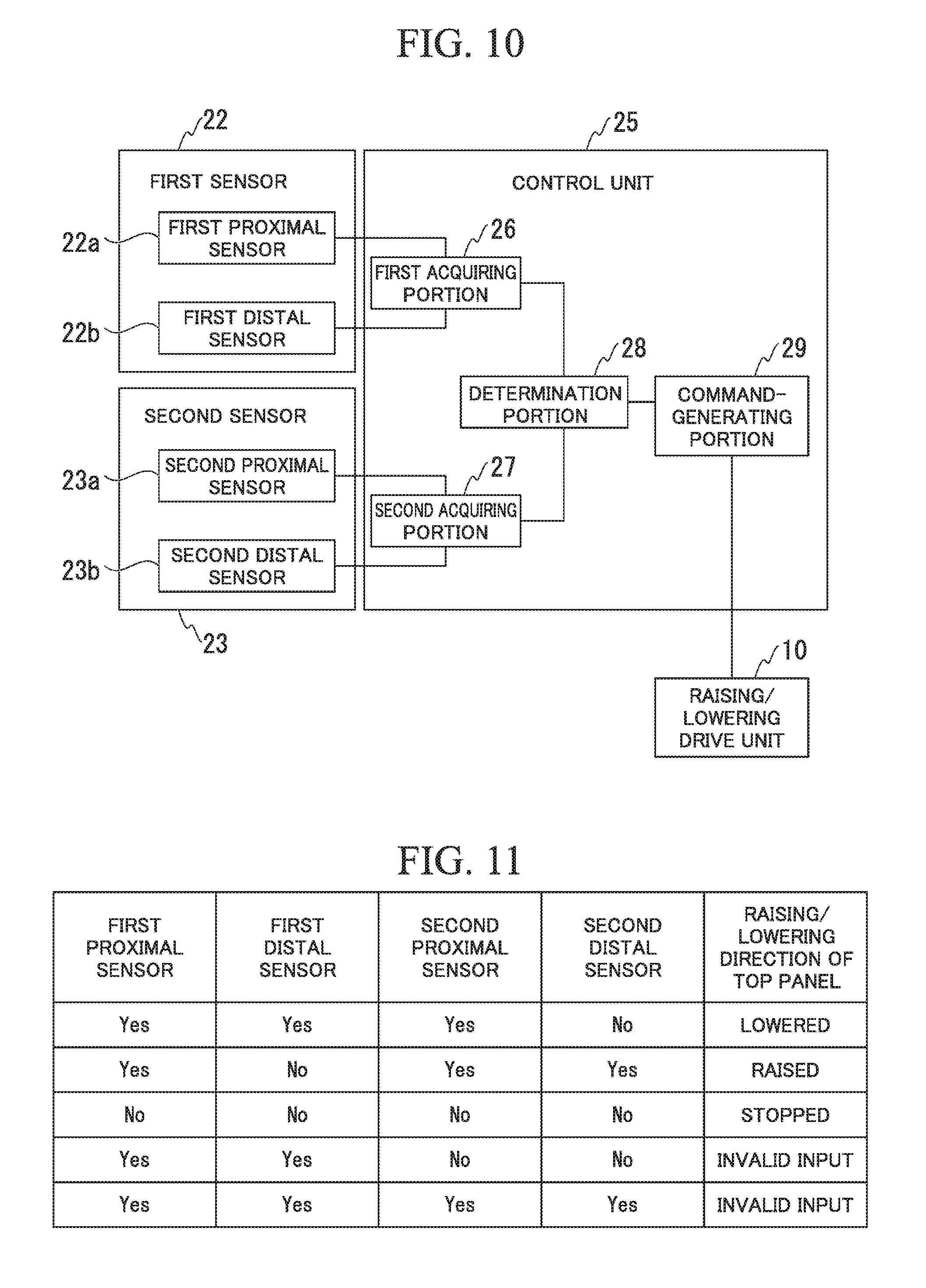
[0065] FIG. 10 is a block diagram of the top panel height adjustable furniture according to the second embodiment of the present invention.
[0066] FIG. 11 is a table showing raising/lowering control of the top panel in the top panel height adjustable furniture according to the second embodiment of the present invention.
[0067] FIG. 12 is a view describing a case in which the top panel is lowered through a raising/lowering operation of the top panel in the top panel height adjustable furniture according to the second embodiment of the present invention.
[0068] FIG. 13 is a view describing a case in which the top panel is raised through a raising/lowering operation of the top panel in the top panel height adjustable furniture according to the second embodiment of the present invention.
[0069] FIG. 14 is a view of top panel height adjustable furniture according to a third embodiment of the present invention seen from a side surface side of the top panel.
[0070] FIG. 15 is a perspective view of top panel height adjustable furniture according to a seventh embodiment of the present invention.
[0071] FIG. 16 is a view of the top panel height adjustable furniture according to the seventh embodiment of the present invention seen from the upper surface side of the top panel.
[0072] FIG. 17 is a view of the top panel height adjustable furniture according to the seventh embodiment of the present invention seen from the lower surface side of the top panel.
[0073] FIG. 18 is a block diagram of the top panel height adjustable furniture according to the seventh embodiment of the present invention.
[0074] FIG. 19A is a table showing raising/lowering control of the top panel in the top panel height adjustable furniture according to the seventh embodiment of the present invention.
[0075] FIG. 19B is another table showing raising/lowering control of the top panel in the top panel height adjustable furniture according to the seventh embodiment of the present invention.
[0076] FIG. 20 is a view describing a case in which the top panel is lowered through a raising/lowering operation of the top panel in the top panel height adjustable furniture according to the seventh embodiment of the present invention.
[0077] FIG. 21 is a view describing a case in which the top panel is raised through a raising/lowering operation of the top panel in the top panel height adjustable furniture according to the seventh embodiment of the present invention.
[0078] FIG. 22 is a view of top panel height adjustable furniture according to an eighth embodiment of the present invention seen from the upper surface side of the top panel.
[0079] FIG. 23 is a view of the top panel height adjustable furniture according to the eighth embodiment of the present invention seen from the lower surface side of the top panel.
[0080] FIG. 24 is a block diagram of the top panel height adjustable furniture according to the eighth embodiment of the present invention.
[0081] FIG. 25 is a table showing raising/lowering control of the top panel in the top panel height adjustable furniture according to the eighth embodiment of the present invention.
[0082] FIG. 26 is a view of top panel height adjustable furniture according to a ninth embodiment of the present invention seen from the side surface side of the top panel.
[0083] FIG. 27 is a block diagram of top panel height adjustable furniture according to a tenth embodiment of the present invention.
[0084] FIG. 28A is a table showing raising/lowering control of the top panel in the top panel height adjustable furniture according to the tenth embodiment of the present invention.
[0085] FIG. 28B is another table showing raising/lowering control of the top panel in the top panel height adjustable furniture according to the tenth embodiment of the present invention
DESCRIPTION OF EMBODIMENTS
First Embodiment
[0086] A first embodiment of the present invention will be described. FIG. 1 is a perspective view of top panel height adjustable furniture of the present embodiment. FIG. 2 is a view of the top panel height adjustable furniture seen from an upper surface side of a top panel. FIG. 3 is a view of the top panel height adjustable furniture seen from a lower surface side of the top panel.
[0087] As illustrated in FIGS. 1 to 3, top panel height adjustable furniture 1 (which will hereinafter be simply referred to as "furniture 1") of the present embodiment includes a top panel 2, support bodies 5, a sensor 11, and a control unit 15.
[0088] The top panel 2 has an upper surface 3 and a lower surface 4. The top panel 2 has recesses for attaching the sensor 11 (which will be described below) in the vicinity of a front end portion 2a of the top panel 2. Other configurations of the top panel 2 are not particularly limited.
[0089] The support body 5 has a beam portion 6, a shaft portion 7, a leg portion 8, and a raising/lowering drive unit 10.
[0090] The beam portion 6 extends in a forward/rearward direction of the top panel 2. The beam portion 6 is installed one each at right and left ends of the top panel 2.
[0091] The shaft portion 7 is connected to the top panel 2 via the beam portion 6. The shaft portion 7 extends vertically downward from the lower surface 4 of the top panel 2.
[0092] The leg portion 8 comes into contact with a floor surface to support the furniture 1 of the present embodiment and is coupled to the shaft portion 7 via the raising/lowering drive unit 10. In the present embodiment, the leg portion 8 has a horizontal portion 8a which extends parallel to the floor surface, and a first cylinder portion 8b and a second cylinder portion 8c which vertically extend while being coaxial with the shaft portion 7.
[0093] The raising/lowering drive unit 10 includes a motor and a gear (not illustrated) for relatively moving the shaft portion 7, the first cylinder portion 8b, and the second cylinder portion 8c in a longitudinal axis direction of the shaft portion 7, the first cylinder portion 8b, and the second cylinder portion 8c. The raising/lowering drive unit 10 is electrically connected to the control unit 15. When the raising/lowering drive unit 10 operates, the support bodies 5 extend or contract in a panel thickness direction of the top panel 2.
[0094] As illustrated in FIGS. 2 and 3, the sensor 11 includes a first sensor 12 which is installed on the upper surface 3 of the top panel 2, and a second sensor 13 which is installed on the lower surface 4 of the top panel 2.
[0095] The first sensor 12 is a contact sensor which is capable of detecting contact of a user with the upper surface 3 of the top panel 2. The first sensor 12 is installed in the front end portion 2a of the top panel 2 on the upper surface 3 of the top panel 2. The first sensor 12 extends along a width direction of the top panel 2 (a direction indicated with the reference sign X in FIG. 2) in the front end portion 2a of the top panel 2. An outer surface of the first sensor 12 is positioned on substantially the same surface as the upper surface 3 of the top panel 2.
[0096] The first sensor 12 of the present embodiment includes a right sensor 12a and a left sensor 12b. The distance between the right sensor 12a and the left sensor 12b is a distance at which a body (for example, an arm) of a user using the furniture 1 does not simultaneously come into contact with the right sensor 12a and the left sensor 12b when the furniture 1 is in ordinary use (when a raising/lowering operation of the top panel 2 is not performed). For example, the distance between the right sensor 12a and the left sensor 12b is wider than the width across the shoulders of the user. In addition, the distance between the right sensor 12a and the left sensor 12b is set such that the user's body can simultaneously come into contact with the right sensor 12a and the left sensor 12b when a raising/lowering operation of the top panel 2 is performed. For example, the distance between the right sensor 12a and the left sensor 12b is shorter than the distance between the right and left palms of the user in a state in which the user opens his/her arms to the right and the left. A part of the first sensor 12 which comes into contact with the user's body in ordinary use, in which the top panel of the furniture 1 is not raised or lowered, may be set as a dead zone (a region in which detection of the first sensor 12 is invalid) depending on the user's physique or usage conditions.
[0097] The second sensor 13 is a contact sensor which is capable of detecting contact of the user with the lower surface 4 of the top panel 2. The second sensor 13 is installed in the front end portion 2a of the top panel 2 on the lower surface 4 of the top panel 2. The second sensor 13 extends along the width direction of the top panel 2 (a direction indicated with the reference sign X in FIG. 3) in the front end portion 2a of the top panel 2. An outer surface of the second sensor 13 is positioned on substantially the same surface as the lower surface 4 of the top panel 2.
[0098] The second sensor 13 of the present embodiment includes a right sensor 13a and a left sensor 13b. The distance between the right sensor 13a and the left sensor 13b is a distance at which a body (for example, a thigh) of the user using the furniture 1 does not simultaneously come into contact with the right sensor 13a and the left sensor 13b when the furniture 1 is in ordinary use (when a raising/lowering operation of the top panel 2 is not performed).
[0099] As illustrated in FIG. 6, when seen from the upper surface 3 toward the lower surface 4 of the top panel 2 (in a vertical direction in FIG. 6), the first sensor 12 and the second sensor 13 are disposed such that the first sensor 12 and the second sensor 13 overlap each other.
[0100] FIG. 4 is a block diagram of the top panel height adjustable furniture. FIGS. 5A and 5B are tables showing raising/lowering control of the top panel in the top panel height adjustable furniture.
[0101] As illustrated in FIGS. 1 and 4, the control unit 15 controls an extending/contracting operation of the support body 5 based on detection results of the sensor 11. For example, the control unit 15 is installed inside the support body 5.
[0102] As illustrated in FIG. 4, the control unit 15 has a first acquiring portion 16, a second acquiring portion 17, a determination portion 18, and a command-generating portion 19.
[0103] The first acquiring portion 16 is connected to the first sensor 12. The first acquiring portion 16 acquires information of the presence or absence of contact of the user with respect to the first sensor 12. In the present embodiment, the first acquiring portion 16 acquires information of the presence or absence of contact of the user with respect to each of the right sensor 12a and the left sensor 12b constituting the first sensor 12, and the information is stored in the first acquiring portion 16 to be able to be referred to in the determination portion 18.
[0104] The second acquiring portion 17 is connected to the second sensor 13. The second acquiring portion 17 acquires information of the presence or absence of contact of the user with respect to the second sensor 13. In the present embodiment, the second acquiring portion 17 acquires information of the presence or absence of contact of the user with respect to each of the right sensor 13a and the left sensor 13b constituting the second sensor 13, and the information is stored in the second acquiring portion 17 to be able to be referred to in the determination portion 18.
[0105] The determination portion 18 is connected to the first acquiring portion 16 and the second acquiring portion 17. The determination portion 18 determines which of the first sensor 12 and the second sensor 13 the user has made contact, based on information acquired by the first acquiring portion 16 from the first sensor 12 and information acquired by the second acquiring portion 17 from the second sensor 13.
[0106] As illustrated in FIGS. 5A and 5B, when information of the presence of contact of the user with respect to the right sensor 12a and the left sensor 12b constituting the first sensor 12 is acquired by the first acquiring portion 16, the determination portion 18 in the present embodiment determines that there has been a valid input to the first sensor 12. In this case, the determination portion 18 outputs a signal for lowering the top panel 2 to the command-generating portion 19.
[0107] Moreover, when information of the presence of contact of the user with respect to the right sensor 13a and the left sensor 13b constituting the second sensor 13 is acquired by the second acquiring portion 17, the determination portion 18 in the present embodiment determines that there has been a valid input to the second sensor 13. In this case, the determination portion 18 outputs a signal for raising the top panel 2 to the command-generating portion 19.
[0108] When it is determined that there has been an input to the first sensor 12 and it is also determined that there has been an input to the second sensor 13, the determination portion 18 in the present embodiment determines that these inputs are invalid.
[0109] The command-generating portion 19 causes the top panel 2 to be raised or lowered in response to an output from the determination portion 18. In the present embodiment, the command-generating portion 19 generates a command for an extending/contracting operation of the support body 5 and outputs the command to the raising/lowering drive unit 10 provided in the support body 5 in response to an output from the determination portion 18. That is, when a signal for lowering the top panel 2 is output from the determination portion 18 to the command-generating portion 19, the command-generating portion 19 generates a command for contracting the support bodies 5 and outputs the command to the raising/lowering drive unit 10. In addition, when a signal for raising the top panel 2 is output from the determination portion 18 to the command-generating portion 19, the command-generating portion 19 generates a command for extending the support bodies 5 and outputs the command to the raising/lowering drive unit 10.
[0110] Operations of the furniture 1 of the present embodiment will be described. FIG. 6 is a view describing a case in which the top panel is lowered through a raising/lowering operation of the top panel in the top panel height adjustable furniture. FIG. 7 is a view describing a case in which the top panel is raised through a raising/lowering operation of the top panel in the top panel height adjustable furniture.
[0111] When the user raises or lowers the top panel 2 of the furniture 1 of the present embodiment, as illustrated in FIG. 6, the user brings his/her hands into contact with the upper surface 3 or the lower surface 4 in the front end portion 2a of the top panel 2.
[0112] For example, when the user lowers the top panel 2, the user brings his/her hands into contact with the upper surface 3 of the top panel 2. This is a gesture of the user for pushing down the top panel 2. If the user brings his/her hands into contact with the upper surface 3 of the top panel 2, the user's hands conic into contact with the first sensor 12. In the present embodiment, when the user's hands come into contact with both the right sensor 12a and the left sensor 12b constituting the first sensor 12 (refer to FIG. 2), the control unit 15 determines that there has been contact with the first sensor 12. The control unit 15 causes the support bodies 5 to contract based on contact with the first sensor 12. Accordingly, the top panel 2 is lowered.
[0113] In addition, when the user raises the top panel 2, as illustrated in FIG. 7, the user brings his/her hands into contact with the lower surface 4 of the top panel 2. This is a gesture of the user for pushing up the top panel 2. If the user brings his/her hands into contact with the lower surface 4 of the top panel 2, the user's hands come into contact with the second sensor 13. In the present embodiment, when the user's hands come into contact with both the right sensor 13a and the left sensor 13b constituting the second sensor 13 (refer to FIG. 3), the control unit 15 determines that there has been contact with the second sensor 13. The control unit 15 causes the support bodies 5 to extend based on contact with the second sensor 13. Accordingly, the top panel 2 is raised.
[0114] In the furniture 1 of the present embodiment, the user can raise or lower the top panel 2 with a force lighter than that of actually pushing down or pushing up the top panel 2 by using an intuitive gesture for raising or lowering the top panel 2. According to the furniture 1 of the present embodiment, a raising/lowering operation of the top panel 2 can be intuitively performed. In addition, according to the furniture 1 of the present embodiment, a raising/lowering operation of the top panel 2 can be easily performed.
[0115] In addition, the first sensor 12 and the second sensor 13 are disposed at positions overlapping each other when seen from the upper surface 3 toward the lower surface 4 of the top panel 2. Therefore, it is easy for the user to know a position with which his/her hands have to come into contact when the top panel 2 is raised and a position with which his/her hand has to come into contact when the top panel 2 is lowered.
[0116] In addition, the outer surface of the first sensor 12 is positioned on substantially the same surface as the upper surface 3 of the top panel 2. Therefore, a part in the vicinity of the front end of the top panel 2 has excellent design.
[0117] In addition, the outer surface of the second sensor 13 is positioned on substantially the same surface as the lower surface 4 of the top panel 2. Therefore, a foot, baggage, or the like of the user is unlikely to be caught by the lower surface 4 in the vicinity of the front end of the top panel 2.
[0118] In addition, the first sensor 12 and the second sensor 13 are disposed along the width direction of the top panel 2. Therefore, the user can perform a raising/lowering operation of the top panel 2 in a natural posture regardless of his/her physique.
Second Embodiment
[0119] A second embodiment of the present invention will be described. HG 8 is a view of top panel height adjustable furniture of the present embodiment seen from the upper surface side of the top panel. FIG. 9 is a view of the top panel height adjustable furniture seen from the lower surface side of the top panel.
[0120] FIG. 10 is a block diagram of the top panel height adjustable furniture. FIG. 11 is a table showing raising/lowering control of the top panel in the top panel height adjustable furniture. FIG. 12 is a view describing a case in which the top panel is lowered through a raising/lowering operation of the top panel in the top panel height adjustable furniture. FIG. 13 is a view describing a case in which the top panel is raised through a raising/lowering operation of the top panel in the top panel height adjustable furniture.
[0121] As illustrated in FIGS. 8 and 9, in place of the sensor 11 disclosed in the first embodiment, furniture 20 of the present embodiment includes a sensor 21 that can determine in which of the upward direction and the downward direction the user intends to move the top panel 2 by discriminating the direction of the user's hand. In addition, the furniture 20 of the present embodiment includes a control unit 25 which is different from the control unit 15 in the first embodiment.
[0122] The sensor 21 of the present embodiment includes a first sensor 22 which is installed on the upper surface 3 of the top panel 2, and a second sensor 23 which is installed on the lower surface 4 of the top panel 2.
[0123] The first sensor 22 includes a first proximal sensor 22a and a first distal sensor 22b.
[0124] The first proximal sensor 22a and the first distal sensor 22b extend along the width direction of the top panel 2 while being parallel to each other at a distance therebetween.
[0125] The first proximal sensor 22a is installed at a position (refer to FIG. 13) with which the first finger (thumb) of the user's hand can come into contact when the user grasps the top panel 2 in a manner pinching the front end portion 2a of the top panel 2.
[0126] The first distal sensor 22b is installed at a position (refer to FIG. 12) with which at least any of the second finger to the fifth finger of the user's hand can come into contact when the user grasps the top panel 2 in a manner pinching the front end portion 2a of the top panel 2.
[0127] The second sensor 23 includes a second proximal sensor 23a and a second distal sensor 23b.
[0128] The second proximal sensor 23a and the second distal sensor 23b extend along the width direction of the top panel 2 while being parallel to each other at a distance therebetween. The second proximal sensor 23a is installed at a position (refer to FIG. 12) with which the first finger (thumb) of the user's hand can come into contact when the user grasps the top panel 2 in a manner pinching the front end portion 2a of the top panel 2. The second distal sensor 23b is installed at a position (refer to FIG. 13) with which at least any of the second finger to the fifth finger of the user's hand can come into contact when the user grasps the top panel 2 in a manner pinching the front end portion 2a of the top panel 2.
[0129] As illustrated in FIG. 10, the control unit 25 has a first acquiring portion 26, a second acquiring portion 27, a determination portion 28, and a command-generating portion 29.
[0130] The first acquiring portion 26 is connected to the first sensor 22. The first acquiring portion 26 acquires information of the presence or absence of contact of the user with respect to the first sensor 22. In the present embodiment, the first acquiring portion 26 acquires information of the presence or absence of contact of the user with respect to each of the first proximal sensor 22a and the first distal sensor 22b constituting the first sensor 22, and the information is stored in the first acquiring portion 26 to be able to be referred to in the determination portion 28.
[0131] The second acquiring portion 27 is connected to the second sensor 23. The second acquiring portion 27 acquires information of the presence or absence of contact of the user with respect to the second sensor 23. In the present embodiment, the second acquiring portion 27 acquires information of the presence or absence of contact of the user with respect to each of the second proximal sensor 23a and the second distal sensor 23b constituting the second sensor 23, and the information is stored in the second acquiring portion 27 to be able to be referred to in the determination portion 28.
[0132] The determination portion 28 is connected to the first acquiring portion 26 and the second acquiring portion 27. The determination portion 28 determines which of the first sensor 22 and the second sensor 23 the user has made contact, based on information acquired by the first acquiring portion 26 from the first sensor 22 and information acquired by the second acquiring portion 27 from the second sensor 23.
[0133] As illustrated in FIG. 11, when contact with the first proximal sensor 22a, the first distal sensor 22b, and the second proximal sensor 23a is detected and contact with the second distal sensor 23b is not detected, the determination portion 28 outputs a signal for lowering the top panel 2 to the command-generating portion 29.
[0134] In addition, when contact with the first proximal sensor 22a, the second proximal sensor 23a, and the second distal sensor 23b is detected and contact with the first distal sensor 22b is not detected, the determination portion 28 outputs a signal for raising the top panel 2 to the command-generating portion 29.
[0135] As illustrated in FIG. 11, when there is an input to the first proximal sensor 22a and the first distal sensor 22b and there is no input to the second proximal sensor 23a and the second distal sensor 23b, the determination portion 28 in the present embodiment determines that these inputs are invalid. Therefore, while the top panel 2 is in ordinary use such that the user has brought his/her arm into contact with the upper surface 3 of the top panel 2, the top panel 2 is not raised or lowered.
[0136] In addition, when it is determined that there also has been an input to all of the first proximal sensor 22a, the first distal sensor 22b, the second proximal sensor 23a, and the second distal sensor 23b, the determination portion 28 in the present embodiment determines that these inputs are invalid. Therefore, the top panel 2 can be stopped when the lower surface 4 of the top panel 2 comes into contact with a knee or the like while the user is lowering the top panel 2.
[0137] The command-generating portion 29 causes the top panel 2 to be raised or lowered in response to an output from the determination portion 28. In the present embodiment, the command-generating portion 29 generates a command for an extending/contracting operation of the support body 5 and outputs the command to the raising/lowering drive unit 10 provided in the support body 5 in response to an output from the determination portion 28. That is, when a signal for lowering the top panel 2 is output from the determination portion 28 to the command-generating portion 29, the command-generating portion 29 generates a command for contracting the support bodies 5 and outputs the command to the raising/lowering drive unit 10. In addition, when a signal for raising the top panel 2 is output from the determination portion 28 to the command-generating portion 29, the command-generating portion 29 generates a command for extending the support bodies 5 and outputs the command to the raising/lowering drive unit 10.
[0138] Operations of the furniture 20 of the present embodiment will be described.
[0139] The control unit 25 of the present embodiment determines in which of the upward direction and the downward direction the user intends to move the top panel 2, based on the presence or absence of contact with respect to each of the first proximal sensor 22a, the first distal sensor 22b, the second proximal sensor 23a, and the second distal sensor 23b.
[0140] In the present embodiment, when the user's hand is in contact with the upper surface 3 of the top panel 2 in a manner in which the palm of the user's hand intending to raise or lower the top panel 2 is directed downward (refer to FIG. 12), the user's hand comes into contact with both the first proximal sensor 22a and the first distal sensor 22b of the first sensor 22. In addition, in this case, if the user is grasping the front end portion 2a of the top panel 2 to lower the top panel 2, the user's hand is also in contact with the second proximal sensor 23a of the second sensor 23. Therefore, when contact with the first proximal sensor 22a, the first distal sensor 22b, and the second proximal sensor 23a is detected and contact with the second distal sensor 23b is not detected, the control unit 25 outputs a signal for contracting the support bodies 5 to the raising/lowering drive unit 10. Accordingly, the raising/lowering drive unit 10 lowers the top panel 2 in accordance with a gesture for grasping and pushing down the front end portion 2a of the top panel 2.
[0141] On the contrary, when the user's hand is in contact with the lower surface 4 of the top panel 2 in a manner in which the palm of the user's hand intending to raise or lower the top panel 2 is directed upward (refer to FIG. 13), the user's hand comes into contact with both the second proximal sensor 23a and the second distal sensor 23b of the second sensor 23. In addition, in this case, if the user is grasping the front end portion 2a of the top panel 2 to raise the top panel 2, the user's hand is also in contact with the first proximal sensor 22a of the first sensor 22. Therefore, when contact with the first proximal sensor 22a, the second proximal sensor 23a, and the second distal sensor 23b is detected and contact with the first distal sensor 22b is not detected, the control unit 25 outputs a signal for extending the support bodies 5 to the raising/lowering drive unit 10. Accordingly, the raising/lowering drive unit 10 raises the top panel 2 in accordance with a gesture for grasping and pushing up the front end portion 2a of the top panel 2.
[0142] The furniture 20 of the present embodiment exhibits effects similar to those of the first embodiment.
[0143] In addition, in the present embodiment, when the user performs an operation of raising or lowering the top panel 2, the user grasps the top panel 2 in a manner pinching the front end portion 2a of the top panel 2, so that the user's hand comes into contact with both the first sensor 22 and the second sensor 23. Here, the user's first finger (thumb) does not reach the distal sensor (the first distal sensor 22b or the second distal sensor 23b) but any of the second finger to the fifth finger of the user reaches the distal sensor (the first distal sensor 22b or the second distal sensor 23b), the control unit 25 can determine the direction of the user's hand by using the first sensor 22 and the second sensor 23.
[0144] In the present embodiment, a natural direction of the hand of the user when the user lowers the top panel 2 is a direction of grasping the front end portion 2a of the top panel 2 with a hand while the back of the hand is directed upward. In addition, a natural direction of the hand of the user when the user raises the top panel 2 is a direction of grasping the front end portion 2a of the top panel 2 with a hand while the back of the hand is directed downward.
[0145] In the present embodiment, the top panel 2 can be raised or lowered by grasping the front end portion 2a of the top panel 2 with one hand. In addition, in the present embodiment, when the user only grasps the top panel 2, the control unit 25 determines the raising/lowering direction of the top panel 2 and causes the support bodies 5 to extend and contract. Therefore, the top panel 2 can be raised or lowered with a light force.
Modification Example
[0146] A modification example of the present embodiment will be described.
[0147] In the present modification example, in place of the first sensor 22 and the second sensor 23 installed in the top panel, many contact sensors are installed on the upper surface of the top panel and many contact sensors are installed on the lower surface of the top panel. In the present modification example, the sensors installed in the top panel are different from that in the second embodiment described above and are arranged in a zigzag shape or a square lattice shape. In the present modification example, the sensors installed in the top panel are connected to the control unit.
[0148] In the present modification example, the control unit acquires the positions and the number of sensors, among many sensors installed on the upper surface of the top panel, which have detected contact of the user's hand and the positions and the number of sensors, among many sensors installed on the lower surface of the top panel, which have detected contact of the user's hand. The control unit estimates the posture of the user's hand which made contact with the top panel using the detection positions and the detection numbers of the sensors on each of the upper surface and the lower surface of the top panel.
[0149] In the present modification example as well, similar to the second embodiment described above, the top panel can be raised or lowered by grasping the front end portion of the top panel with one hand.
[0150] In place of many sensors installed on the upper surface and the lower surface of the top panel, a sensor which detects the contact state of the user's hand with respect to a predetermined region in the vicinity of the front end portion of the top panel may be installed in the top panel. For example, an electrostatic capacitance-type sensor, a resistive film-type sensor, or the like which can receive a multi-touch input may be installed on the upper surface and the lower surface in the front end portion of the top panel.
Third Embodiment
[0151] A third embodiment of the present invention will be described. FIG. 14 is a view of top panel height adjustable furniture of the present embodiment seen from a side surface side of the top panel.
[0152] As illustrated in FIG. 14, in place of the sensor 11 disclosed in the first embodiment, furniture 30 of the present embodiment has a distortion sensor 31 which detects distortion of the top panel 2 caused by contact of the user with respect to the top panel 2. Examples of the distortion sensor 31 may include a sensor using a piezoelectric element.
[0153] The position of the distortion sensor 31 is not particularly limited and need only be a position at which distortion of the top panel 2 can be detected. For example, the distortion sensor 31 may be installed in a connection part between the top panel 2 and the support body 5.
[0154] The control unit of the present embodiment causes the support bodies 5 to contract while the distortion sensor 31 is detecting distortion generated in the top panel 2 caused by the user pushing the upper surface 3 of the top panel 2 to the lower surface 4 side. The control unit causes the support bodies 5 to extend while the distortion sensor 31 is detecting distortion generated in the top panel 2 caused by the user pushing the lower surface 4 of the top panel 2 to the upper surface 3 side.
[0155] The furniture 30 of the present embodiment exhibits effects similar to those of the first embodiment.
[0156] In addition, the position of the distortion sensor 31 in the furniture 30 of the present embodiment is not limited to the front end portion 2a of the top panel 2 and need only be a position at which distortion generated in the top panel 2 can be detected when the user intends to raise or lower the top panel 2. Therefore, even if the distortion sensor 31 is disposed at a position where the user cannot touch the distortion sensor 31 with his/her hand in the top panel 2, a gesture of the user for raising or lowering the top panel 2 can be recognized based on distortion of the top panel 2.
Fourth Embodiment
[0157] A fourth embodiment of the present invention will be described.
[0158] A sensor for raising and lowering the top panel in top panel height adjustable furniture of the present embodiment has push-button switches which are installed on the upper surface and the lower surface of the top panel. The push-button switches installed on the upper surface and the lower surface of the top panel are connected to the control unit.
[0159] The push-button switch installed on the upper surface of the top panel is a switch to be pushed through an operation of the user on the upper surface side of the top panel. If the push-button switch installed on the upper surface of the top panel is pushed, the top panel is lowered in a manner similar to the cases of the embodiments described above in which the user has made contact with the first sensor 12. The push-button switch installed on the lower surface of the top panel is a switch to be pushed through an operation of the user on the lower surface side of the top panel. If the push-button switch installed on the lower surface of the top panel is pushed, the top panel is raised in a manner similar to the cases of the embodiments described above in which the user has made contact with the second sensor 13.
Fifth Embodiment
[0160] A fifth embodiment of the present invention will be described.
[0161] Top panel height adjustable furniture of the present embodiment differs from that of the first embodiment described above in installing a sensor in a part other than the top panel in the top panel height adjustable furniture. As an example, the sensor of the top panel height adjustable furniture of the present embodiment is installed in the support body. The sensor of the present embodiment is a distortion sensor, instead of a contact sensor. The distortion sensor can detect distortion caused by contact of the user's hand with the top panel. The distortion sensor is connected to the control unit which controls raising and lowering of the top panel. The configuration of the control unit may be similar to that of the first embodiment described above.
[0162] In the top panel height adjustable furniture of the present embodiment, a case in which the user's hand comes into contact with the upper surface of the top panel and a case in which the user's hand comes into contact with the lower surface of the top panel differ from each other in the distortion state detected by the distortion sensor. Accordingly, the control unit can identify which of the upper surface and the lower surface of the top panel the user intends to come into contact and in which of the upward direction and the downward direction the user intends to move the top panel.
[0163] The top panel height adjustable furniture of the present embodiment also exhibits effects similar to those of the first embodiment. In addition, since the top panel height adjustable furniture of the present embodiment has no sensor on the upper surface of the top panel, the entire area of the upper surface of the top panel can be used as a work surface. Accordingly, the top panel height adjustable furniture of the present embodiment has excellent usability as furniture.
Sixth Embodiment
[0164] A sixth embodiment of the present invention will be described.
[0165] Top panel height adjustable furniture of the present embodiment differs from that of each of the embodiments described above in that the speed of raising and lowering of the top panel can be changed.
[0166] In addition to the sensor 11 disclosed in the first embodiment described above, the top panel height adjustable furniture of the present embodiment has a distortion sensor which can detect the degree of distortion generated in the top panel. The distortion sensor is installed in a part, such as the top panel or the support body, to which distortion generated in the top panel is transferred. The distortion sensor is connected to the control unit which controls raising and lowering of the top panel.
[0167] The degree of an input to the distortion sensor varies depending on the magnitude of a pushing force with respect to the top panel. That is, in the present embodiment, the presence or absence of an input to the sensor 11 that is a contact sensor becomes a trigger for a raising/lowering operation of the top panel, and the degree of an input to the distortion sensor corresponds to the magnitude of a force of the user moving the top panel. When an input to the distortion sensor is significant, it is estimated that the user intends to promptly raise or lower the top panel. Therefore, the control unit controls a raising/lowering operation of the support body such that the raising/lowering speed of the top panel becomes higher than a standard speed. When an input to the distortion sensor is reduced, the control unit controls a raising/lowering operation of the support body such that the raising/lowering speed of the top panel approximates the standard speed. In addition, when an input to the distortion sensor is extremely small, it is estimated that the user intends to perform fine adjustment of the height of the top panel, and the control unit can control a raising/lowering operation of the support body such that the raising/lowering speed of the top panel becomes lower than the standard speed.
[0168] The top panel height adjustable furniture of the present embodiment also exhibits effects similar to those of the first embodiment described above. Moreover, the top panel height adjustable furniture of the present embodiment can automatically switch between a prompt raising/lowering operation of the top panel and fine adjustment of the height of the top panel by reflecting the raising/lowering speed of the top panel intended by the user.
Modification Example
[0169] A modification example of the present embodiment will be described.
[0170] In the present modification example, in place of the distortion sensor included in the top panel height adjustable furniture, the sensor 11 is configured to be able to perform a detection operation corresponding to the contact area of the user's hand.
[0171] For example, the sensor 11 has many fine sensor elements in certain regions on the upper surface and the lower surface of the top panel in the vicinity of the front end portion of the top panel. As an example, the sensor 11 includes a known electrostatic capacitance-type sensor and a known resistive film-type sensor utilized in touch panels for multi-touch.
[0172] The control unit connected to the sensor 11 of the present modification example controls the speed of a raising/lowering operation of the support body based on the contact area of the user's hand.
[0173] For example, the control unit stores a threshold value which has been set in advance in consideration of the size of the hand of a person assumed as the user. As an example, between a contact area when the user brings one finger into contact with the top panel and a contact area when the user brings the entire palm of the hand into contact with the top panel, the contact area when the entire palm of the hand is brought into contact with the top panel is larger. In such a contact state, it is estimated that the user intends to more promptly raise or lower the top panel than when one finger is brought into contact with the top panel. Therefore, when the contact area exceeds a predetermined threshold value, the control unit performs control of increasing the raising/lowering speed of the top panel by the support bodies. On the contrary, when the contact area is equal to or smaller than the predetermined threshold value, the control unit performs control of decreasing the raising/lowering speed of the top panel by the support bodies.
[0174] In addition, the control unit periodically acquires the contact area from the point of time when the user's hand has made contact with the sensor 11 and estimates a change in a force of the user pushing the top panel, based on the change amount or the change rate of the contact area. In this case, when the contact area increases, the control unit determines that the top panel is further pushed, and the control unit performs control of increasing the raising/lowering speed of the top panel by the support bodies. On the contrary, when the contact area is reduced, the control unit determines that pushing with respect to the top panel is reduced, and the control unit performs control of decreasing the raising/lowering speed of the top panel by the support bodies.
[0175] The top panel height adjustable furniture of the present modification example also exhibits effects similar to those of the sixth embodiment described above.
Seventh Embodiment
[0176] A seventh embodiment of the present invention will be described. FIG. 15 is a perspective view of top panel height adjustable furniture of the present embodiment. FIG. 16 is a view of the top panel height adjustable furniture seen from the upper surface side of the top panel. FIG. 17 is a view of the top panel height adjustable furniture seen from the lower surface side of the top panel.
[0177] As illustrated in FIGS. 15 to 17, in place of the sensor 11 disclosed in the first embodiment, furniture 101 of the present embodiment includes a sensor 111. In addition, the furniture 101 of the present embodiment includes a control unit 115 different from the control unit 15 disclosed in the first embodiment.
[0178] As illustrated in FIGS. 15 to 17, the sensor 111 has the first sensor 12 which is installed on the upper surface 3 of the top panel 2, the second sensor 13 which is installed on the lower surface 4 of the top panel 2, and third sensors (receiving portions) 14 which are installed in the support bodies 5. The first sensor 12 and the second sensor 13 of the present embodiment have configurations similar to those of the first sensor 12 and the second sensor 13 of the first embodiment. Here, description thereof will be omitted.
[0179] The third sensor 14 is a sensor for receiving an input of permission or inhibition of raising or lowering of the top panel 2. The third sensor 14 of the present embodiment is attached to the horizontal portion 8a of the leg portion 8 such that the user can perform an operation with a foot. When the user steps on the third sensor 14 with a foot, the third sensor 14 switches between a first state permitting the top panel 2 to be raised or lowered and a second state inhibiting the top panel 2 from being raised or lowered. The third sensor 14 is electrically connected to the control unit 115.
[0180] FIG. 18 is a block diagram of the top panel height adjustable furniture. FIGS. 19A and 19B are tables showing raising/lowering control of the top panel in the top panel height adjustable furniture.
[0181] As illustrated in FIGS. 15 and 18, the control unit 115 controls an extending/contracting operation of the support body 5 based on a detection result of the sensor 111. For example, the control unit 115 is installed inside the support body 5.
[0182] As illustrated in FIG. 18, the control unit 115 has a first acquiring portion 116a, a second acquiring portion 116b, a third acquiring portion 117, a determination portion 118, and a command-generating portion 119.
[0183] The first acquiring portion 116a and the second acquiring portion 116b acquire information of the presence or absence of an input to the first sensor 12 and the second sensor 13, in regard to an operation of the user raising or lowering the top panel 2.
[0184] The first acquiring portion 116a is connected to the first sensor 12. The first acquiring portion 116a acquires information of the presence or absence of contact of the user with respect to the first sensor 12. In the present embodiment, the first acquiring portion 116a acquires information of the presence or absence of contact of the user with respect to each of the right sensor 12a and the left sensor 12b constituting the first sensor 12, and the information is stored in the first acquiring portion 116a to be able to be referred to in the determination portion 118.
[0185] The second acquiring portion 116b is connected to the second sensor 13. The second acquiring portion 116b acquires information of the presence or absence of contact of the user with respect to the second sensor 13. In the present embodiment, the second acquiring portion 116b acquires information of the presence or absence of contact of the user with respect to each of the right sensor 13a and the left sensor 13b constituting the second sensor 13, and the information is stored in the second acquiring portion 116b to be able to be referred to in the determination portion 118.
[0186] The third acquiring portion 117 acquires information indicating whether or not the operation with respect to the first acquiring portion 116a and the second acquiring portion 116b is a valid operation, based on the presence or absence of an input to the third sensor 14. For example, when there is an input to the third sensor 14, the third acquiring portion 117 outputs, to the determination portion 118, a signal indicating that an input to the first acquiring portion 116a and the second acquiring portion 116b is valid.
[0187] The determination portion 118 is connected to the first acquiring portion 116a and the second acquiring portion 116b. The determination portion 118 determines which of the first sensor 12 and the second sensor 13 the user has made contact, based on information acquired by the first acquiring portion 116a from the first sensor 12 and information acquired by the second acquiring portion 116b from the second sensor 13. In addition, the determination portion 118 determines whether or not to perform an output of a signal to the command-generating portion 119, based on the presence or absence of a signal from the third acquiring portion 117.
[0188] As illustrated in FIGS. 19A and 19B, when information of the presence of contact of the user with respect to the right sensor 12a and the left sensor 12b constituting the first sensor 12 is acquired by the first acquiring portion 116a, the determination portion 118 in the present embodiment determines that there has been an input to the first sensor 12. In this case, if an elapsed time after the determination portion 118 receives the signal from the third acquiring portion 117 is within a predetermined period of time, the determination portion 118 outputs a signal for lowering the top panel 2 to the command-generating portion 119.
[0189] Moreover, when information of the presence of contact of the user with respect to the right sensor 13a and the left sensor 13b constituting the second sensor 13 is acquired by the second acquiring portion 116b, the determination portion 118 in the present embodiment determines that there has been an input to the second sensor 13. In this case, if the elapsed time after the determination portion 118 receives the signal from the third acquiring portion 117 is within a predetermined period of time, the determination portion 118 outputs a signal for raising the top panel 2 to the command-generating portion 119.
[0190] When it is determined that there has been an input to the first sensor 12 and it is also determined that there has been an input to the second sensor 13, the determination portion 118 in the present embodiment determines that these inputs are invalid.
[0191] In addition, when there is no input to the third sensor 14 after the predetermined period of time has elapsed after the determination portion 118 receives the signal from the third acquiring portion 117, the determination portion 118 in the present embodiment inhibits a signal from being output to the command-generating portion 119 (inhibits the top panel from moving).
[0192] The command-generating portion 119 causes the top panel 2 to be raised or lowered in response to an output from the determination portion 118. In the present embodiment, the command-generating portion 119 generates a command for an extending/contracting operation of the support body 5 in response to an output from the determination portion 118 and outputs the command to the raising/lowering drive unit 10 provided in the support body 5. That is, when a signal for lowering the top panel 2 is output from the determination portion 118 to the command-generating portion 119, the command-generating portion 119 generates a command for contracting the support bodies 5 and outputs the command to the raising/lowering drive unit 10. In addition, when a signal for raising the top panel 2 is output from the determination portion 118 to the command-generating portion 119, the command-generating portion 119 generates a command for extending the support bodies 5 and outputs the command to the raising/lowering drive unit 10.
[0193] Operations of the control unit 115 of the present embodiment will be described.
[0194] The control unit 115 has a mode (top panel raising/lowering mode) in which the support bodies 5 extend or contract in response to an input to the first sensor 12 or the second sensor 13 and a mode (top panel movement inhibiting mode) in which an extending/contracting operation of the support body 5 is inhibited at all times regardless of the presence or absence of an input to the first sensor 12 or the second sensor 13, in accordance with an input state with respect to the third sensor 14 (refer to FIG. 19B). For example, the control unit 115 operates in the mode in which the support bodies 5 extend or contract, for the predetermined period of time after the point of time when there has been an input to the third sensor 14. The control unit 115 shifts to the mode in which an extending/contracting operation of the support body 5 is inhibited when there is no input to the first sensor 12 or the second sensor 13 even if this predetermined period of time has elapsed.
[0195] In a state where the top panel 2 is permitted to be raised or lowered by the third sensor 14, when the user is in contact with the first sensor 12, the control unit 115 of the present embodiment determines that the user has made contact with the top panel 2 on the upper surface 3 side of the top panel 2. In this case, the control unit 115 outputs a signal for contracting the support bodies 5 to the raising/lowering drive unit 10 of the support body 5.
[0196] In addition, in the state where the top panel 2 is permitted to be raised or lowered by the third sensor 14, when the user is in contact with the second sensor 13, the control unit 115 of the present embodiment determines that the user has made contact with the top panel 2 on the lower surface 4 side of the top panel 2. In this case, the control unit 115 outputs a signal for extending the support bodies 5 to the raising/lowering drive unit 10 of the support body 5.
[0197] Operations of the furniture 101 of the present embodiment will be described. FIG. 20 is a view describing a case in which the top panel is lowered through a raising/lowering operation of the top panel in the top panel height adjustable furniture. FIG. 21 is a view describing a case in which the top panel is raised through a raising/lowering operation of the top panel in the top panel height adjustable furniture.
[0198] When the user raises or lowers the top panel 2 of the furniture 101 of the present embodiment, the user steps on the third sensor 14 with a foot and permits the top panel 2 to be raised or lowered. If the user steps on the third sensor 14 with a foot and there is an input to the third sensor 14, the control unit 115 shifts to the mode in which the support bodies 5 extend or contract in response to an input to the first sensor 12 or the second sensor 13. Within the predetermined period of time while the control unit 115 operates in the mode in which the support bodies 5 extend or contract, as illustrated in FIG. 20, the user brings his/her hands into contact with the upper surface 3 or the lower surface 4 in the front end portion 2a of the top panel 2.
[0199] For example, when the user lowers the top panel 2, the user brings his/her hands into contact with the upper surface 3 of the top panel 2. This is a gesture of the user for pushing down the top panel 2. If the user brings his/her hands into contact with the upper surface 3 of the top panel 2, the user's hands come into contact with the first sensor 12. In the present embodiment, when the user's hands come into contact with both the right sensor 12a and the left sensor 12b constituting the first sensor 12 (refer to FIG. 16), the control unit 115 determines that there has been contact with the first sensor 12. The control unit 115 causes the support bodies 5 to contract based on contact with the first sensor 12. Accordingly, the top panel 2 is lowered.
[0200] In addition, when the user raises the top panel 2, as illustrated in FIG. 21, the user brings his/her hands into contact with the lower surface 4 of the top panel 2. This is a gesture of the user for pushing up the top panel 2. If the user brings his/her hands into contact with the lower surface 4 of the top panel 2, the user's hands come into contact with the second sensor 13. In the present embodiment, when the user's hands come into contact with both the right sensor 13a and the left sensor 13b constituting the second sensor 13 (refer to FIG. 17), the control unit 115 determines that there has been contact with the second sensor 13. The control unit 115 causes the support bodies 5 to extend based on contact with the second sensor 13. Accordingly, the top panel 2 is raised.
[0201] The furniture 101 of the present embodiment exhibits effects similar to those of the first embodiment.
[0202] In addition, the top panel 2 can be raised or lowered by using the first sensor 12 or the second sensor 13 only when permission for raising or lowering of the top panel 2 is input by the third sensor 14 (receiving portion). Therefore, it is possible to reduce a possibility that the top panel 2 is unintentionally raised or lowered.
[0203] In addition, in the furniture 101 of the present embodiment, at least one of the first sensor 12 and the second sensor 13 (in the present embodiment, the first sensor 12) is installed on the upper surface 3 of the top panel 2.
[0204] In this case, it is easy to make an input to each of the sensors 12 and 13. In addition, if the first sensor 12 or the second sensor 13 is disposed at a position where an input is easily made, there may also be a possibility of an erroneous input. However, since the third sensor 14 (receiving portion) is provided, even if there is an erroneous input, an erroneous operation of the top panel 2 is hardly caused.
[0205] In addition, in the furniture 101 of the present embodiment, the first sensor 12 is a contact sensor which is installed on the upper surface 3 of the top panel 2 and detects contact of the user. The second sensor 13 is a contact sensor which is installed on the lower surface 4 of the top panel 2 and detects contact of the user.
[0206] In this case, when the user comes into contact with the upper surface 3 of the top panel 2 in an operation in which the user pushes down the top panel 2 to lower the top panel 2, the control unit 115 can cause the top panel 2 to be lowered by controlling the support bodies 5. In addition, when the user comes into contact with the lower surface 4 of the top panel 2 in an operation in which the user pushes up the top panel 2 to raise the top panel 2, the control unit 115 can cause the top panel 2 to be raised by controlling the support bodies 5. As a result, a force of the user to be applied to the top panel 2 to move the top panel 2 is reduced, and the top panel 2 can be raised or lowered in a natural posture.
Modification Example
[0207] A modification example of the present embodiment will be described.
[0208] In the present modification example, while an input to the third sensor 14 (a state of stepping on the third sensor 14 with a foot) continues, the control unit 115 operates in the mode in which the support bodies 5 extend or contract, and if an input to the third sensor 14 is canceled, the control unit 115 operates in the mode in which an extending/contracting operation of the support body 5 is inhibited.
[0209] Even such a configuration exhibits effects similar to those of the embodiments described above.
[0210] In addition, in the present modification example, the user's intention of raising or lowering the top panel 2 can be determined based on an input to the third sensor 14. Therefore, there is no need for the user to touch both the right sensor 12a and the left sensor 12b in the first sensor 12 with both hands, or there is no need for the user to touch both the right sensor 13a and the left sensor 13b in the second sensor 13 with both hands.
[0211] Therefore, in the present modification example, a raising/lowering operation of the top panel 2 can be performed with one hand.
Eighth Embodiment
[0212] An eighth embodiment of the present invention will be described. FIG. 22 is a view of top panel height adjustable furniture of the present embodiment seen from the upper surface side of the top panel. FIG. 23 is a view of the top panel height adjustable furniture seen from the lower surface side of the top panel.
[0213] FIG. 24 is a block diagram of the top panel height adjustable furniture. FIG. 25 is a table showing raising/lowering control of the top panel in the top panel height adjustable furniture.
[0214] As illustrated in FIGS. 8 and 9, in place of the sensor 111 disclosed in the seventh embodiment, furniture 120 of the present embodiment includes a sensor 121 that can determine in which of the upward direction and the downward direction the user intends to move the top panel 2 by discriminating the direction of the user's hand. In addition, the furniture 120 of the present embodiment includes a control unit 125 which is different from the control unit 115 disclosed in the seventh embodiment.
[0215] The sensor 121 of the present embodiment has the first sensor 22 which is installed on the upper surface 3 of the top panel 2, the second sensor 23 which is installed on the lower surface 4 of the top panel 2, and the third sensors (receiving portions) 14 which are installed in the support bodies 5. The first sensor 22 and the second sensor 23 of the present embodiment have configurations similar to those of the first sensor 22 and the second sensor 23 of the second embodiment. Here, description thereof will be omitted. The third sensor 14 of the present embodiment has a configuration similar to that of the third sensor 14 of the seventh embodiment. Here, description thereof will be omitted.
[0216] As illustrated in FIG. 24, the control unit 125 has a first acquiring portion 126a, a second acquiring portion 126b, a third acquiring portion 127, a determination portion 128, and a command-generating portion 129.
[0217] The first acquiring portion 126a is connected to the first sensor 22. The first acquiring portion 126a acquires information of the presence or absence of contact of the user with respect to the first sensor 22. In the present embodiment, the first acquiring portion 126a acquires information of the presence or absence of contact of the user with respect to each of the first proximal sensor 22a and the first distal sensor 22b constituting the first sensor 22, and the information is stored in the first acquiring portion 126a to be able to be referred to in the determination portion 128.
[0218] The second acquiring portion 126b is connected to the second sensor 23. The second acquiring portion 126b acquires information of the presence or absence of contact of the user with respect to the second sensor 23. In the present embodiment, the second acquiring portion 126b acquires information of the presence or absence of contact of the user with respect to each of the second proximal sensor 23a and the second distal sensor 23b constituting the second sensor 23, and the information is stored in the second acquiring portion 126b to be able to be referred to in the determination portion 128.
[0219] The third acquiring portion 127 acquires information indicating whether or not the operation with respect to the first acquiring portion 126a and the second acquiring portion 126b is a valid operation, based on the presence or absence of an input to the third sensor 14. For example, when there is an input to the third sensor 14, the third acquiring portion 127 outputs, to the determination portion 128, a signal indicating that an input to the first acquiring portion 126a and the second acquiring portion 126b is valid.
[0220] The determination portion 128 is connected to the first acquiring portion 126a and the second acquiring portion 126b. The determination portion 128 determines which of the first sensor 22 and the second sensor 23 the user has made contact, based on information acquired by the first acquiring portion 126a from the first sensor 22 and information acquired by the second acquiring portion 126b from the second sensor 23.
[0221] When contact with the first proximal sensor 22a, the first distal sensor 22b, and the second proximal sensor 23a is detected and contact with the second distal sensor 23b is not detected, the determination portion 128 outputs a signal for lowering the top panel 2 to the command-generating portion 129 (refer to FIG. 25).
[0222] In addition, when contact with the first proximal sensor 22a, the second proximal sensor 23a, and the second distal sensor 23b is detected and contact with the first distal sensor 22b is not detected, the determination portion 128 outputs a signal for raising the top panel 2 to the command-generating portion 129 (refer to FIG. 25).
[0223] As illustrated in FIG. 25, when there is an input to the first proximal sensor 22a and the first distal sensor 22b and there is no input to the second proximal sensor 23a and the second distal sensor 23b, the determination portion 128 in the present embodiment determines that these inputs are invalid. Therefore, while the top panel 2 is in ordinary use such that the user has brought his/her arm into contact with the upper surface 3 of the top panel 2, the top panel 2 is not raised or lowered.
[0224] In addition, when it is determined that there also has been an input to all of the first proximal sensor 22a, the first distal sensor 22b, the second proximal sensor 23a, and the second distal sensor 23b, the determination portion 128 in the present embodiment determines that these inputs are invalid. Therefore, the top panel 2 can be stopped when the lower surface 4 of the top panel 2 comes into contact with a knee or the like while the user is lowering the top panel 2.
[0225] The command-generating portion 129 causes the top panel 2 to be raised or lowered in response to an output from the determination portion 128. In the present embodiment, the command-generating portion 129 generates a command for an extending/contracting operation of the support body 5 and outputs the command to the raising/lowering drive unit 10 provided in the support body 5 in response to an output from the determination portion 128. That is, when a signal for lowering the top panel 2 is output from the determination portion 128 to the command-generating portion 129, the command-generating portion 129 generates a command for contracting the support bodies 5 and outputs the command to the raising/lowering drive unit 10. In addition, when a signal for raising the top panel 2 is output from the determination portion 128 to the command-generating portion 129, the command-generating portion 129 generates a command for extending the support body 5 and outputs the command to the raising/lowering drive unit 10.
[0226] Operations of the furniture 120 of the present embodiment will be described.
[0227] The control unit 125 of the present embodiment determines in which of the upward direction and the downward direction the user intends to move the top panel 2, based on the presence or absence of contact with respect to each of the first proximal sensor 22a, the first distal sensor 22b, the second proximal sensor 23a, and the second distal sensor 23b. In the present embodiment as well, similar to the seventh embodiment, the control unit 125 refers to the presence or absence of an input to the third sensor 14 and operates in either one mode of the mode in which the support bodies 5 extend or contract or the mode in which an extending/contracting operation of the support body 5 is inhibited (refer to FIG. 25).
[0228] In the present embodiment, when the user's hand is in contact with the upper surface 3 of the top panel 2 in a manner in which the palm of the user's hand intending to raise or lower the top panel 2 is directed downward, the user's hand comes into contact with both the first proximal sensor 22a and the first distal sensor 22b of the first sensor 22. In addition, in this case, if the user is grasping the front end portion 2a of the top panel 2 to lower the top panel 2, the user's hand is also in contact with the second proximal sensor 23a of the second sensor 23. Therefore, when contact with the first proximal sensor 22a, the first distal sensor 22b, and the second proximal sensor 23a is detected and contact with the second distal sensor 23b is not detected, the control unit 125 outputs a signal for contracting the support bodies 5 to the raising/lowering drive unit 10. Accordingly, the raising/lowering drive units 10 lower the top panel 2 in accordance with a gesture for grasping and pushing down the front end portion 2a of the top panel 2.
[0229] On the contrary, when the user's hand is in contact with the lower surface 4 of the top panel 2 in a manner in which the palm of the user's hand intending to raise or lower the top panel 2 is directed upward, the user's hand comes into contact with both the second proximal sensor 23a and the second distal sensor 23b of the second sensor 23. In addition, in this case, if the user is grasping the front end portion 2a of the top panel 2 to raise the top panel 2, the user's hand is also in contact with the first proximal sensor 22a of the first sensor 22. Therefore, when contact with the first proximal sensor 22a, the second proximal sensor 23a, and the second distal sensor 23b is detected and contact with the first distal sensor 22b is not detected, the control unit 125 outputs a signal for extending the support bodies 5 to the raising/lowering drive unit 10. Accordingly, the raising/lowering drive units 10 raise the top panel 2 in accordance with a gesture for grasping and pushing up the front end portion 2a of the top panel 2.
[0230] The furniture 120 of the present embodiment exhibits effects similar to those of the seventh embodiment. In addition, the furniture 120 of the present embodiment exhibits effects similar to those of the second embodiment.
Ninth Embodiment
[0231] A ninth embodiment of the present invention will be described. FIG. 26 is a view of top panel height adjustable furniture of the present embodiment seen from the side surface side of the top panel.
[0232] As illustrated in FIG. 26, in place of the first sensor 12 and the second sensor 13 disclosed in the seventh embodiment, furniture 130 of the present embodiment has the distortion sensor 31 which detects distortion of the top panel 2 caused by contact of the user with respect to the top panel 2. The distortion sensor 31 of the present embodiment has a configuration similar to that of the distortion sensor 31 of the third embodiment. Here, description thereof will be omitted.
[0233] When permission for raising or lowering of the top panel 2 is input to the third sensor 14 (receiving portion), the control unit of the present embodiment causes the support bodies 5 to contract while the distortion sensor 31 is detecting distortion generated in the top panel 2 by the user pushing the upper surface 3 of the top panel 2 to the lower surface 4 side, and the control unit causes the support bodies 5 to extend while the distortion sensor 31 is detecting distortion generated in the top panel 2 by the user pushing the lower surface 4 of the top panel 2 to the upper surface 3 side.
[0234] The furniture 130 of the present embodiment exhibits effects similar to those of the seventh embodiment. In addition, the furniture 130 of the present embodiment exhibits effects similar to those of the third embodiment.
Tenth Embodiment
[0235] A tenth embodiment of the present invention will be described.
[0236] FIG. 27 is a block diagram of top panel height adjustable furniture of the present embodiment. FIGS. 28A and 28B are tables showing raising/lowering control of the top panel in the top panel height adjustable furniture.
[0237] Top panel height adjustable furniture 140 of the present embodiment has a control unit 145 having a configuration partially different from that of the control unit 115 disclosed in the seventh embodiment described above. In addition, the top panel height adjustable furniture 140 of the present embodiment does not have the third sensor 14.
[0238] The control unit 145 has a determination portion 146 which determines whether or not a signal is output to the command-generating portion 119, based on the acquired condition of information of the first acquiring portion 116a and the second acquiring portion 116b, in place of the determination portion 118 in the seventh embodiment.
[0239] FIGS. 28A and 28B illustrate a relationship between the presence or absence of contact with each of the sensors for making selection between permission and inhibition of movement of the top panel 2, and a determination result of the determination portion 146. In FIGS. 28A and 28B, "Yes" indicates that there is contact of the user exceeding the predetermined period of time. In FIGS. 28A and 28B, "No" indicates that there is no contact of the user exceeding the predetermined period of time.
[0240] As illustrated in FIG. 28A, the determination portion 146 in the present embodiment determines whether or not there is contact of the user with both the first sensor 12 and the second sensor 13 exceeding the predetermined period of time, based on information acquired by the first acquiring portion 116a and the second acquiring portion 116b.
[0241] For example, as illustrated in FIG. 28B, when the user is in contact with both the right sensor 12a and the right sensor 13a exceeding the predetermined period of time, the determination portion 146 determines that there is contact of the user with both the first sensor 12 and the second sensor 13 exceeding the predetermined period of time.
[0242] In addition, when the user is in contact with both the left sensor 12b and the left sensor 13b exceeding the predetermined period of time, the determination portion 146 determines that there is contact of the user with both the first sensor 12 and the second sensor 13 exceeding the predetermined period of time. In addition, when there is contact of the user with the right sensor 12a, the left sensor 12b, the right sensor 13a, and the left sensor 13b exceeding the predetermined period of time, the determination portion 146 may determine that there is contact of the user with both the first sensor 12 and the second sensor 13 exceeding the predetermined period of time.
[0243] When these determinations are performed, the determination portion 146 permit an output of a signal to the command-generating portion 119. If it is not determined that there is contact of the user with both the first sensor 12 and the second sensor 13 exceeding the predetermined period of time, the determination portion 146 inhibits an output of a signal to the command-generating portion 119.
[0244] When information of the presence of contact of the user with respect to the right sensor 12a and the left sensor 12b constituting the first sensor 12 is acquired by the first acquiring portion 116a, the determination portion 146 in the present embodiment determines that there has been an input to the first sensor 12. In this case, if an output of a signal to the command-generating portion 19 is permitted, the determination portion 146 outputs a signal for lowering the top panel 2 to the command-generating portion 19.
[0245] Moreover, when information of the presence of contact of the user with respect to the right sensor 13a and the left sensor 13b constituting the second sensor 13 is acquired by the second acquiring portion 116b, the determination portion 146 in the present embodiment determines that there has been an input to the second sensor 13. In this case, if an output of a signal to the command-generating portion 119 is permitted, the determination portion 146 outputs a signal for raising the top panel 2 to the command-generating portion 119.
[0246] The determination portion 146 of the top panel height adjustable furniture 140 of the present embodiment functions as a receiving portion which receives an input of permission or inhibition of raising or lowering of the top panel 2.
[0247] For example, the third sensor 14 disclosed in the seventh embodiment is configured to be operated by the user with a foot. Therefore, when the user's foot does not reach the third sensor 14, usability may deteriorate. In contrast, the top panel height adjustable furniture 140 of the present embodiment uses the first sensor 12 and the second sensor 13 in place of the third sensor 14, so that permission or inhibition of raising or lowering of the top panel 2 can be selected. Therefore, the top panel height adjustable furniture 140 of the present embodiment has favorable usability for example when the top panel 2 is wide and the distance between the user and the support body 5 is long.
[0248] Hereinabove, the embodiments of the present invention have been described in detail with reference to the drawings. However, a specific configuration is not limited to these embodiments, and a design change and the like within a range not departing from the gist of the present invention are also included.
[0249] For example, the furniture disclosed in the third embodiment and the ninth embodiment described above may be able to detect contact with another object by a distortion sensor when the top panel comes into contact with the object while the top panel is raised or lowered. At this time, for example, the control unit can perform control, such as temporarily stopping an extending/contracting operation of the support body.
[0250] In addition, in the furniture disclosed in each of the embodiments described above, the support body may be connected to the side surface of the top panel. In this case, the supporting position of the top panel may be controlled in response to control of the control unit causing a connection structure between the support body and the top panel to vertically move, instead of extending and contracting of the support body.
[0251] In addition, the first sensor disclosed in the seventh embodiment is installed on the upper surface of the top panel, and the second sensor disclosed in the seventh embodiment is installed on the lower surface of the top panel. However, the position of each of the sensors is not limited thereto. As an example, the first sensor and the second sensor may be attached to the lower surface of the top panel as push-button switches in an arranged manner. In addition, the first sensor and the second sensor may be attached to the side surface in the front end portion of the top panel.
[0252] In addition, the third sensor may be installed in the top panel instead of the support body. In this case, the third sensor may be operated with a hand on a side opposite to the hand used for raising or lowering the top panel, instead of being operated with a foot.
INDUSTRIAL APPLICABILITY
[0253] According to the present invention, a raising/lowering operation of a top panel can be intuitively and easily performed.
[0254] In addition, according to the present invention, an erroneous raising/lowering operation of the top panel is hardly caused.
DESCRIPTION OF REFERENCE SIGNS
[0255] 1, 20, 30, 101, 120, 130, 140 Top panel height adjustable furniture [0256] 2 Top panel [0257] 3 Upper surface of top panel [0258] 4 Lower surface of top panel [0259] 5 Support body [0260] 6 Beam portion [0261] 7 Shaft portion [0262] 8 Leg portion [0263] 10 Raising/lowering drive unit [0264] 11, 21, 111, 121 Sensor [0265] 12, 22 First sensor [0266] 13, 23 Second sensor [0267] 14 Third sensor (receiving portion) [0268] 15, 25, 115, 125, 145 Control unit [0269] 16, 26, 116a, 126a First acquiring portion [0270] 17, 27, 116b, 126b Second acquiring portion [0271] 117, 127 Third acquiring portion [0272] 18, 28, 118, 128, 146 Determination portion [0273] 19, 29, 119, 129 Command-generating portion
* * * * *
D00000
D00001
D00002
D00003
D00004
D00005
D00006
D00007
D00008
D00009
D00010
D00011
D00012

D00013

D00014

D00015

D00016

D00017

D00018

D00019

D00020

D00021

XML
uspto.report is an independent third-party trademark research tool that is not affiliated, endorsed, or sponsored by the United States Patent and Trademark Office (USPTO) or any other governmental organization. The information provided by uspto.report is based on publicly available data at the time of writing and is intended for informational purposes only.
While we strive to provide accurate and up-to-date information, we do not guarantee the accuracy, completeness, reliability, or suitability of the information displayed on this site. The use of this site is at your own risk. Any reliance you place on such information is therefore strictly at your own risk.
All official trademark data, including owner information, should be verified by visiting the official USPTO website at www.uspto.gov. This site is not intended to replace professional legal advice and should not be used as a substitute for consulting with a legal professional who is knowledgeable about trademark law.