Extended Heat Sink Design In Server
CHEN; Chao-Jung ; et al.
U.S. patent application number 15/926068 was filed with the patent office on 2019-09-26 for extended heat sink design in server. The applicant listed for this patent is QUANTA COMPUTER INC.. Invention is credited to Chao-Jung CHEN, Yi-Chieh CHEN, Yi-Ta HSU, Yueh-Chang WU.
| Application Number | 20190297748 15/926068 |
| Document ID | / |
| Family ID | 63491372 |
| Filed Date | 2019-09-26 |


| United States Patent Application | 20190297748 |
| Kind Code | A1 |
| CHEN; Chao-Jung ; et al. | September 26, 2019 |
EXTENDED HEAT SINK DESIGN IN SERVER
Abstract
A method and structure for improving efficiency of cooling and temperature uniformity among a plurality of heat generating electronic devices arranged in rows within a housing, such as a GPU server, utilizing a single source of cooling air. The electronic devices are arranged in a plurality of rows, but the heat sinks for the last row are elevated above the heat sinks of the first row so as to occupy different positions within the cooling air stream. In some embodiments the heat sinks of the electronic devices are extended forward so as to reside near the heat sinks of the electronic devices in the first row, but in a different flow path of cooling air. In other embodiments, a thermo siphon refrigeration system is provided for the electronic devices in the last row, and may be provided for the electronic devices in the first row as well.
| Inventors: | CHEN; Chao-Jung; (Taoyuan City, TW) ; CHEN; Yi-Chieh; (Taoyuan City, TW) ; WU; Yueh-Chang; (Taoyuan City, TW) ; HSU; Yi-Ta; (Taoyuan City, TW) | ||||||||||
| Applicant: |
|
||||||||||
|---|---|---|---|---|---|---|---|---|---|---|---|
| Family ID: | 63491372 | ||||||||||
| Appl. No.: | 15/926068 | ||||||||||
| Filed: | March 20, 2018 |
| Current U.S. Class: | 1/1 |
| Current CPC Class: | G06F 1/20 20130101; H05K 7/20809 20130101; H05K 7/20327 20130101; H05K 7/20172 20130101; G06F 2200/201 20130101; H05K 7/20727 20130101; H05K 7/20436 20130101 |
| International Class: | H05K 7/20 20060101 H05K007/20 |
Claims
1. An extended heat sink in an array of a plurality of heat generating processing units wherein the processing units are placed in at least two rows comprising a front row and at least a rear row, and further comprising a source of cooling air causing flow of cooling air in a direction from the front row toward the at least rear row, said extended heat sink comprising: extending a heat sink from a processing unit in the at least rear row.
2. The extended heat sink of claim 1 wherein the front row and the at least rear row are contained in a housing of a server.
3. The extended heat sink of claim 1, wherein the extended heat sink further comprises a refrigeration circuit; the refrigeration circuit comprising a first reservoir for refrigerant in the extended heat sink and a second reservoir for refrigerant in contact with at least one GPU in the rear row and at least one conduit for conveying vapor refrigerant from the second reservoir to the first reservoir, and a second conduit for conveying liquid refrigerant in the first reservoir to the second reservoir.
4. The extended heat sink of claim 3, wherein the conveying of liquid refrigerant in the second conduit is effected by gravity.
5. The extended heat sink of claim 1, wherein the array of processing units numbers eight processing units in total, arranged such that there are four processing units in the first row and four processing units in the last row, and each processing unit in the last row is associated with its own extended heat sink.
6. The extended heat sink of claim 3, wherein the refrigerant is at least one selected from the group consisting of R134a, R22, R12, R407c and R410a.
7. The extended heat sink of claim 5, wherein a temperature difference between a processing unit in the first row and a processing unit in the second row is 3.degree. C. or less.
8. The extended heat sink of claim 1, wherein the source of cooling air comprises at least one fan.
9. The extended heat sink of claim 1, wherein the array of processing units is contained within a housing.
10. A server comprising an array of heat generating processing units arranged in a front row and at least a rear row within a housing, each of the processing units in the array comprising a heat sink and a thermo siphon refrigeration circuit; the refrigeration circuit for each processing unit in the rear row comprising a first reservoir for refrigerant in an extended heat sink and a second reservoir for refrigerant in contact with each processing unit and at least one conduit for conveying vapor refrigerant from the second reservoir to the first reservoir, and a second conduit for conveying liquid refrigerant in the first reservoir to the second reservoir; and the refrigeration circuit for each processing unit in the front row comprising a third reservoir for refrigerant in a heat sink and a fourth reservoir for refrigerant in contact with each processing unit in the front row and at least one conduit for conveying vapor refrigerant from the fourth reservoir to the third reservoir, and a second conduit for conveying liquid refrigerant in the third reservoir to the fourth reservoir
11. The server of claim 10, wherein there are eight processing units arranged into two rows with four processing units in a first row and four processing units in a rear row, the processing units in the rear row each comprising a heat sink positioned within the housing such that it is in a position higher than the heat sink of any processing unit in the first row.
12. The server of claim 11, wherein the heat generating processing units in the rear row have their heat sinks extended within the housing so as to be positioned near the heat sinks of the processing units of the first row.
13. The server of claim 10, wherein the refrigerant is at least one refrigerant selected from the group consisting of R134a, R22, R12, R407c and R410a.
14. A method of improving the heat transfer efficiency of a heat sink associated with heat generating electronic devices cooled by a single flow of cooling air, wherein the heat generating electronic devices are arranged in rows within a housing and each electronic device having its own heat sink, the method comprising elevating the heat sinks of the last row of electronic devices above the height of the heat sinks of the electronic devices in the first row.
15. The method of claim 14, further comprising extending the position of the heat sinks of the electronic devices in the last row so as to be positioned near the heat sinks of the electronic devices of the first row.
16. The method of claim 14, wherein the heat generating electronic devices are at least one selected from the group consisting of GPUs and CPUs.
17. The method of claim 15, further comprising cooling the heat sinks of the electronic devices in the last row with a thermo siphon utilizing a confined refrigerant which is vaporized by the heat generated by the electronic devices in the last row.
18. The method of claim 17, wherein the vaporized refrigerant is condensed into a liquid by removal of heat in the heat sink positioned above the electronic devices of the first row.
19. The method of claim 18, further comprising flowing the condensed liquid by the influence of gravity back towards the heat generating electronic device in the last row and repeating the vaporization of refrigerant step.
20. The method of claim 19, wherein the refrigerant is at least one refrigerant selected from the group consisting of R134a, R22, R12, R407c and R410a.
Description
TECHNICAL FIELD
[0001] In server design, heat build-up is of concern--especially in components downstream of the initial airflow provided by a cooling fan, wherein incoming cooling air is pre-heated before reaching downstream components. Recent developments related to the heat output of graphics processing units (GPUs) and central processing units (CPUs) is becoming critical due to the increasingly higher power required for these units. The present disclosure is directed to reducing the temperature disparity between upstream and downstream components without increasing the power load on the cooling fan. The use of an extended heat sink design reduces the temperature disparity of components.
BACKGROUND
[0002] In server design, increasingly higher power of GPUs is being applied. Currently, the highest power of GPUs is up to 300 W, but will soon increase to 400 W. Current heat sink design by air cooling alone is too limited to solve temperature disparity among GPUs to bring the temperature of the units into specification.
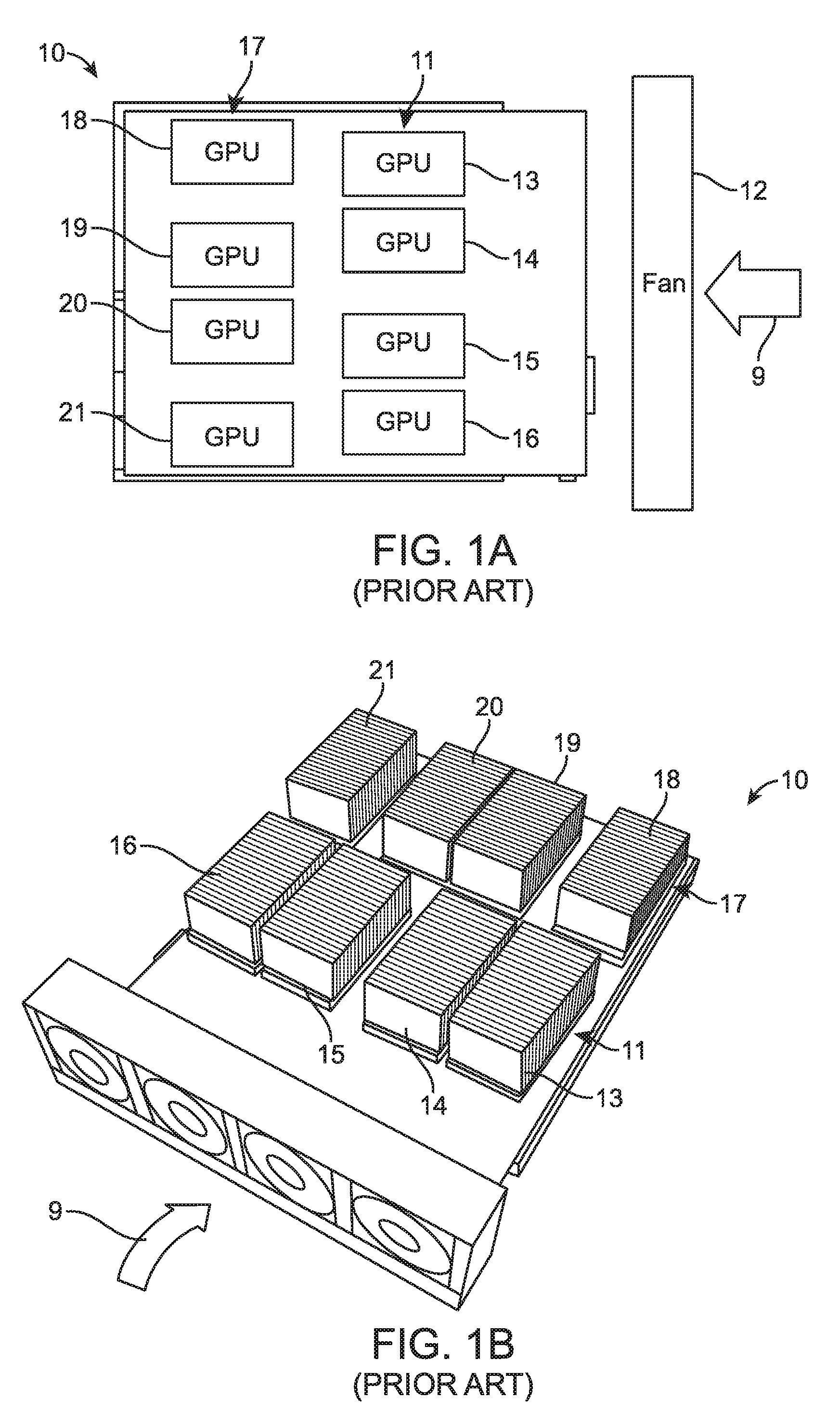
[0003] As an example of the state of the art in the case of an eight piece GPU modules placed in a server as shown in the schematic layout of FIG. 1A (Prior Art). A perspective view of FIG. 1A is shown in FIG. 1B (Prior Art). There is a 2 U to 3 U height space for GPU heat sink. The placement in of 4 GPUs in the front and 4 GPUs in the rear is as shown in FIGS. 1A and 1B. As can be seen from the placement of fan 12 in FIG. 1A, the initial cooling air in the direction of arrow 9 will pass over the first row of 4 GPUs and cool them to specification. However, the heat picked up by the cooling air results in less cooling in the second row of 4 GPUs. As shown in FIG. 2 (Prior Art), there will be a temperature disparity between the first and second rows of GPUs. The front row of GPUs temperature will be on the order of 6-11.degree. C. lower than the temperature of the GPUs in the rear, second row due to this pre-heating of the cooling air. Hence, in this design, there exists these issues: [0004] (a) Poor temperature distribution causes the GPUs located in the worst location to operate at 71.8.degree. C.; [0005] (b) Thermal limitation of supporting GPUs; and [0006] (c) Higher fan power consumption in attempting to bring GPUs in the worst locations into temperature specification.
[0007] The present disclosure presents a structure and method of reducing the temperature disparity among GPUs without increasing power consumption of the fan.
SUMMARY
[0008] In one embodiment of this disclosure, an extended heat sink structure permits more even cooling among the GPUs arranged in an eight piece GPU server.
[0009] In another embodiment, there are provided upper and lower heat sinks separated into different air cooling paths to reduce temperature disparity among the GPUs.
[0010] In a still further embodiment, a thermo-siphon solution is employed where a refrigerant is filled inside a tube and the tube embedded in the extended heat sink.
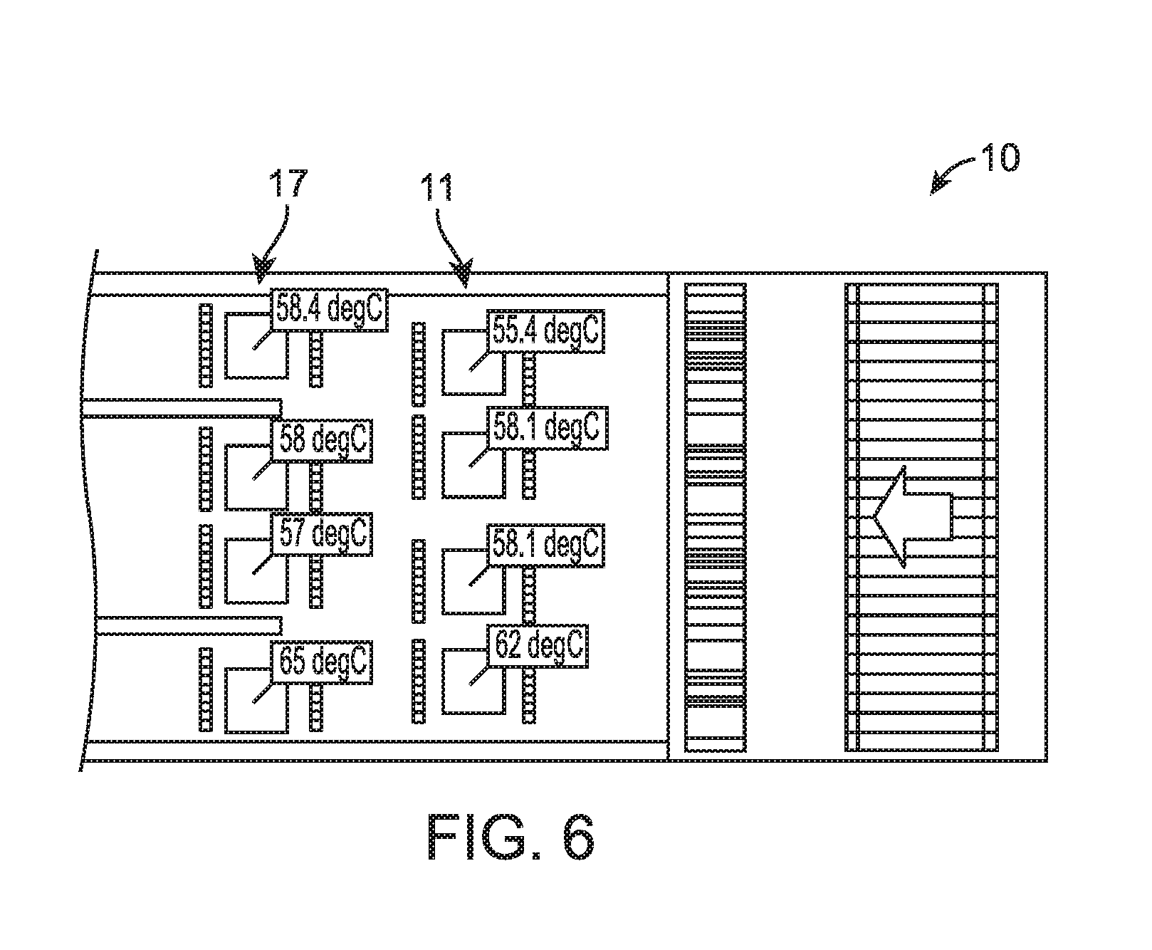
[0011] The disclosure provides a best thermal design with advantages: [0012] (a) No preheating of the cooling air and uniform temperature distribution, with temperature differential between the front and back rows of GPUs reduced to 3.degree. C.; [0013] (b) Best heat transfer efficiency of heat sink; [0014] (c) Reduce worst case temperature location to 65.degree. C.; and, [0015] (d) Lower fan power consumption.
[0016] These and other advantages of the disclosure will be better understood in connection with the detailed description when read in conjunction with the appended drawings.
BRIEF DESCRIPTION OF THE DRAWINGS
[0017] FIG. 1A is a schematic depiction of an eight piece GPU layout in relation to a cooling fan according to the Prior Art.
[0018] FIG. 1B is a perspective view of the eight piece GPU layout of FIG. 1A according to the Prior Art.
[0019] FIG. 2 is a schematic representation of the operating temperatures of the individual GPUs in the eight piece GPU layout of FIGS. 1A and 1B.
[0020] FIG. 3 is a perspective view of the heat sink structure of an eight piece GPU structure according to a first embodiment.
[0021] FIG. 4 is a schematic side view of the eight piece GPU structure of FIG. 3.
[0022] FIG. 5 is a schematic side view of a second embodiment of refrigeration system for the first row 11 of GPUs.
[0023] FIG. 6 is a schematic representation of the operating temperatures of the individual GPUs in the eight piece GPU layout of FIG. 3 according to an embodiment of the disclosure.
DETAILED DESCRIPTION
[0024] The present invention is described with reference to the attached figures, where like reference numerals are used throughout the figures to designate similar or equivalent elements. The figures are not drawn to scale, and they are provided merely to illustrate the instant invention. Several aspects of the invention are described below with reference to example applications for illustration. It should be understood that numerous specific details, relationships, and methods are set forth to provide a full understanding of the invention. One having ordinary skill in the relevant art, however, will readily recognize that the invention can be practiced without one or more of the specific details or with other methods. In other instances, well-known structures or operations are not shown in detail to avoid obscuring the invention. The present invention is not limited by the illustrated ordering of acts or events, as some acts may occur in different orders and/or concurrently with other acts or events. Furthermore, not all illustrated acts or events are required to implement a methodology in accordance with the present invention.
[0025] As shown in FIGS. 1A and 1B is an eight piece GPU server 10 according to the Prior Art. In server 10, fan 12 provides a flow of cooling air in the direction of arrow 9, over the heat sinks associated with the individual GPUs contained in server 10. The heat sinks are conventional heat sinks, such as finned heat sinks, and each is associated with its respective GPU. The individual GPUs, each with their individually associated heat sinks, are arranged into two rows, a front row 11, containing GPUs 13, 14, 15 and 16, respectively, and a rear or second row 17, containing GPUs 18, 19, 20 and 21, respectively. Each of the GPUs contains a heat sink at the same height as any other heat sink in the server 10. Accordingly, the heat sinks are all impinged by the same cooling air flow.
[0026] The cooling air will impinge upon the first row 11 containing GPUs 13, 14, 15 and 16, and cool these GPUs down to and within the operating temperature specification. However, the cooling air will be pre-heated by the first row 11 of GPUs before the cooling air reaches the second row 17 of GPUs 18, 19, 20 and 21. The additional heat carried by the cooling air passing over the first row 11 will mean that the cooling efficiency will not be at peak or optimum value as it impinges on the second row 17 of GPUs.
[0027] As can be seen in FIG. 2, there is a temperature disparity of between 6.degree. C.-11.degree. C. between the first row 11 of GPUs and the second row 17 of GPUs even though both rows are subjected to the same cooling air; and even though all GPUs are operating at the same power levels. The inefficiency of the cooling air is also caused not only by pre-heating of the cooling air as it passes over the first row 11 of GPUs, but also because the pre-heating not only raises the temperature of the cooling air, but also causes eddies in the flow of cooling air which further causes inefficiency of the cooling air impinging upon second row 17 of GPUs. The temperature of the GPUs in the second row causes individual GPUs to operate out of the temperature specifications and further degrades the output of the GPU server 10.
[0028] In order to overcome the temperature disparity in an eight piece GPU server of the prior art, applicant has created the structure of an eight piece GPU server 30, as seen in FIG. 3. The flow of cooling air created by fan 12 in the direction of arrow 9 is still passed over the individual GPUs in the server 30. However, applicant has separated the front row of heat sinks and the rear row of heat sinks into different air cooling paths.
[0029] One embodiment of different cooling paths is shown in the schematic, side view of FIG. 4, the front row 11 in (FIG. 2) of GPU heat sinks are designed at a 1 U to 1.5 U height, but at a lower position than the extended rear GPU heat sink. The rear GPU heat sink is designed at a 1.5 U to 2.0 U upper position, thereby positioning the upper and lower heat sinks in different cooling air paths within housing 48. Another embodiment would be to place the heat sinks of the first row and the heat sinks of the second, or last, row in different flow paths by placing the heat sink for the last row in proximity to, or near, the heat sinks for the first row, but in different cooling air flow paths.
[0030] Furthermore, to further improve the efficiency of the cooling, air flow is increased by the provision of a thermo siphon refrigeration system connected between the extended heat sink and the GPUs of the second row.
[0031] Turning specifically to FIG. 4, where an arrangement of GPUs is carried on motherboard 40, an extended heat sink 42 for GPU 21 is placed in the flow path 9 of cooling air at a height above the flow path of cooling air over the lower placed heat sink for GPU 16. In addition, a refrigeration system, in the form of a thermo siphon system, is shown generally at 43 and comprises a chamber or reservoir 44 in combination with extended heat sink 42. GPU 21 also contains a chamber or reservoir 45, which is operatively connected to reservoir 44 by a pair of conduits 46, 47. The refrigerant in refrigerant system 43 can be any known coolant, such as water or other liquid which boils at a temperature below the boiling point of water, such as a refrigerant discussed in detail below. Vapor created by the heating of GPU 21 flows through conduit 47 in direction of the arrow until it reaches reservoir 44, where it condenses. The condensed coolant in reservoir 44 flows by gravity in direction of arrow 49 through conduit 46 into reservoir 45, where it is again heated and vaporized. It should be understood that a similar arrangement of extended heat sinks exists for each of the rear row GPUs 20, 19 and 18 in the same manner as shown for GPU 21.
[0032] In a still further refinement of the improved cooling structure according to the present embodiments, the front row of 11 of GPUs (in FIG. 2) could also be provided with a refrigerant system, in the form of a thermo siphon system similar in structure and function to that discussed in connection with FIG. 4, as shown in FIG. 5. As shown in FIG. 5, the same arrangement of extended heat sink 42 and refrigeration system 43 is provided, as described in connection with FIG. 4. However, an additional refrigeration system 53, also in the form of a thermo siphon system is provided for the front row of GPUs, as exemplified by GPU 16. Similar to the function of the refrigeration system 43 for the second row of GPUs exemplified by GPU 21, refrigeration system 53 is provided for the first row of GPUs. A reservoir 54 in extended heat sink 52 contains a coolant, such as water, or any liquid that boils at a temperature lower than water, such as a refrigerant. Refrigerants such as R134a, R22, R12, R407c, R410a, etc., and combinations thereof, can be utilized, with R134a being preferred. Reservoir 54 is connected to reservoir 55 associated with GPU 16. Reservoirs 54 and 55 are operatively connected by conduits 56 and 57 respectively, in which a vapor exits reservoir 55 due to heating by GPU 16, and travels via conduit 57 until it condenses in reservoir 54. Condensed liquid refrigerant then flows by gravity through conduit 56 until it reaches reservoir 55, and the cycle begins again. Although illustrations are provided for conduits 46, 47, 56 and 57, in practice, the heat sinks may be surrounded by fins to improve their cooling efficiency such that the conduits are not visible, and the heat sinks may appear as a whole body.
[0033] As shown in the schematic temperature distribution of FIG. 6 for the individual GPUs shown in FIG. 3, the use of the extended heat sinks according to the present embodiment, lowers the temperature differential between the first row 11 and the second row 17 of GPUs to about 3.degree. C. or less. Thus, without increasing the power consumption of the cooling fan, the operating temperatures of the individual GPUs can be reduced and maintained within their operating specification.
[0034] While we have exemplified heat generating GPUs in an array of eight units in two rows, the principles disclosed herein are applicable to any device having heat generating electronic devices comprising eight or more units arranged in two or more rows, as being the sources of heat in a server. As such, it should be regarded by those skilled in the art that the teaching of the instant disclosure can be applied to the cooling of other heat generating electronic devices, such as the cooling of CPUs.
[0035] The terminology used herein is for the purpose of describing particular embodiments only and is not intended to be limiting of the invention. As used herein, the singular forms "a", "an", and "the" are intended to include the plural forms as well, unless the context clearly indicates otherwise. Furthermore, to the extent that the terms "including", "includes", "having", "has", "with", or variants thereof are used in either the detailed description and/or the claims, such terms are intended to be inclusive in a manner similar to the term "comprising."
[0036] Unless otherwise defined, all terms (including technical and scientific terms) used herein have the same meaning as commonly understood by one of ordinary skill in the art to which this invention belongs. It will be further understood that terms, such as those defined in commonly used dictionaries, should be interpreted as having a meaning that is consistent with their meaning in the context of the relevant art and will not be interpreted in an idealized or overly formal sense unless expressly so defined herein.
* * * * *
D00000
D00001
D00002
D00003
D00004
D00005
XML
uspto.report is an independent third-party trademark research tool that is not affiliated, endorsed, or sponsored by the United States Patent and Trademark Office (USPTO) or any other governmental organization. The information provided by uspto.report is based on publicly available data at the time of writing and is intended for informational purposes only.
While we strive to provide accurate and up-to-date information, we do not guarantee the accuracy, completeness, reliability, or suitability of the information displayed on this site. The use of this site is at your own risk. Any reliance you place on such information is therefore strictly at your own risk.
All official trademark data, including owner information, should be verified by visiting the official USPTO website at www.uspto.gov. This site is not intended to replace professional legal advice and should not be used as a substitute for consulting with a legal professional who is knowledgeable about trademark law.