System For Characterizing Manual Welding Operations
BOULWARE; Paul Christopher ; et al.
U.S. patent application number 16/439959 was filed with the patent office on 2019-09-26 for system for characterizing manual welding operations. The applicant listed for this patent is Lincoln Global, Inc.. Invention is credited to Paul Christopher BOULWARE, Douglas A. CLARK, Christopher C. CONRARDY, M. William FORQUER.
| Application Number | 20190295442 16/439959 |
| Document ID | / |
| Family ID | 53496896 |
| Filed Date | 2019-09-26 |


View All Diagrams
| United States Patent Application | 20190295442 |
| Kind Code | A1 |
| BOULWARE; Paul Christopher ; et al. | September 26, 2019 |
SYSTEM FOR CHARACTERIZING MANUAL WELDING OPERATIONS
Abstract
A system for characterizing manual welding exercises and providing valuable training to welders that includes components for generating, capturing, and processing data. The data generating component further includes a fixture, workpiece, at least one calibration devices each having at least two point markers integral therewith, and a welding tool. The data capturing component further includes an imaging system for capturing images of the point markers and the data processing component is operative to receive information from the data capturing component and perform various position and orientation calculations.
| Inventors: | BOULWARE; Paul Christopher; (Columbus, OH) ; CONRARDY; Christopher C.; (Columbus, OH) ; CLARK; Douglas A.; (Columbus, OH) ; FORQUER; M. William; (Columbus, OH) | ||||||||||
| Applicant: |
|
||||||||||
|---|---|---|---|---|---|---|---|---|---|---|---|
| Family ID: | 53496896 | ||||||||||
| Appl. No.: | 16/439959 | ||||||||||
| Filed: | June 13, 2019 |
Related U.S. Patent Documents
| Application Number | Filing Date | Patent Number | ||
|---|---|---|---|---|
| 16021576 | Jun 28, 2018 | 10347154 | ||
| 16439959 | ||||
| 15077532 | Mar 22, 2016 | 10068495 | ||
| 16021576 | ||||
| 14293700 | Jun 2, 2014 | 9773429 | ||
| 15077532 | ||||
| 13543240 | Jul 6, 2012 | 9221117 | ||
| 14293700 | ||||
| 12966570 | Dec 13, 2010 | 9230449 | ||
| 13543240 | ||||
| 12499687 | Jul 8, 2009 | |||
| 12966570 | ||||
| 12499687 | Jul 8, 2009 | |||
| 12966570 | ||||
| 16021576 | Jun 28, 2018 | 10347154 | ||
| 12499687 | ||||
| 15077532 | Mar 22, 2016 | 10068495 | ||
| 16021576 | ||||
| 14293826 | Jun 2, 2014 | |||
| 15077532 | ||||
| 13543240 | Jul 6, 2012 | 9221117 | ||
| 14293826 | ||||
| 12966570 | Dec 13, 2010 | 9230449 | ||
| 13543240 | ||||
| 12499687 | Jul 8, 2009 | |||
| 12966570 | ||||
| 12499687 | Jul 8, 2009 | |||
| 12966570 | ||||
| Current U.S. Class: | 1/1 |
| Current CPC Class: | B23K 9/10 20130101; B23K 9/0956 20130101; G09B 5/02 20130101; G09B 19/24 20130101 |
| International Class: | G09B 19/24 20060101 G09B019/24; G09B 5/02 20060101 G09B005/02; B23K 9/095 20060101 B23K009/095; B23K 9/10 20060101 B23K009/10 |
Claims
1. A method of characterizing a manual welding operation, the method comprising: providing a plurality of welding parameters for a manual welding operation; providing a workpiece to be welded by the manual welding operation; providing a calibration tool, the calibration tool including a plurality of first point markers; providing a welding tool, the welding tool including a plurality of second point markers arranged in a predetermined pattern; placing the workpiece on a weld platform; placing the calibration tool on the weld platform; capturing at least one image of the first point markers of the calibration tool on the weld platform; processing the at least one image of the first point markers on the calibration tool to determine a position and orientation of an operational path for the manual welding operation based on at least one of the welding parameters; manually welding the workpiece with the welding tool; capturing a plurality of images of the second point markers on the welding tool during the manual welding operation; processing the plurality of images of the second point markers on the welding tool to determine a position and orientation of the welding tool; and determining a plurality of characteristics of the manual welding operation based on the position and orientation of the operational path and the position and orientation of the welding tool, wherein the characteristics are selected from the group consisting of: a welding tool work angle, a welding tool travel angle, a welding tool travel speed, a bead placement, and a welding tool standoff distance.
2. The method of claim 1, wherein the weld platform includes a plurality of pins for removably attaching the calibration tool to the weld platform.
3. The method of claim 1, wherein the weld platform includes a plurality of clamps to secure the workpiece to the weld platform.
4. The method of claim 1, wherein the weld platform is connected to a stand.
5. The method of claim 4, further comprising displaying the characteristics on a monitor, wherein the monitor is coupled to the stand.
6. The method of claim 4, wherein the stand includes a vertical support.
7. The method of claim 6, wherein an angle of the weld platform relative to the vertical support is adjustable.
8. The method of claim 6, wherein a height of the weld platform relative to the vertical support is adjustable.
9. The method of claim 4, wherein an optical camera system is coupled to the stand, the optical camera system comprising a plurality of spatially-separated cameras, and wherein the optical camera system is operable to capture images containing at least one of the first point markers and the second point markers.
10. The method of claim 1, wherein the calibration tool is in physical contact with the workpiece on the weld platform.
11. The method of claim 1, wherein the second point markers are active point markers.
12. The method of claim 1, wherein the second point markers are light-emitting point markers.
13. The method of claim 1, further comprising comparing each of the welding tool work angle, the welding tool travel angle, the welding tool travel speed, the bead placement, and the welding tool standoff distance to a corresponding predetermined lower threshold value and a corresponding predetermined upper threshold value.
14. The method of claim 13, further comprising calculating a performance score for the manual welding operation based on the comparison of at least one of the welding tool work angle, the welding tool travel angle, the welding tool travel speed, the bead placement, and the welding tool standoff distance to the corresponding predetermined lower threshold value and the corresponding predetermined upper threshold value.
15. The method of claim 1, further comprising comparing each of the welding tool work angle, the welding tool travel angle, the welding tool travel speed, the bead placement, and the welding tool standoff distance to a corresponding predetermined preferred value.
16. The method of claim 15, further comprising calculating a performance score for the manual welding operation based on the comparison of at least one of the welding tool work angle, the welding tool travel angle, the welding tool travel speed, the bead placement, and the welding tool standoff distance to the corresponding predetermined preferred value.
17. The method of claim 1, wherein the welding tool includes more than three of the second point markers, and wherein the predetermined pattern has no axis of symmetry.
Description
CROSS-REFERENCE TO RELATED APPLICATIONS
[0001] The present application is being filed as a continuation application of U.S. patent application Ser. No. 16/021,576 filed on Jun. 28, 2018, which is a divisional application of U.S. patent application Ser. No. 15/077,532 filed on Mar. 22, 2016, now U.S. Pat. No. 10,068,495 issued on Sep. 4, 2018, which is a continuation of both U.S. patent application Ser. No. 14/293,700 filed on Jun. 2, 2014, now U.S. Pat. No. 9,773,429 issued on Sep. 26, 2017, and U.S. patent application Ser. No. 14/293,826 filed on Jun. 2, 2014, now abandoned, each of which is a continuation-in-part of U.S. patent application Ser. No. 13/543,240 filed on Jul. 6, 2012, now U.S. Pat. No. 9,221,117 issued on Dec. 29, 2015, which is a continuation-in-part of both U.S. patent application Ser. No. 12/966,570 filed on Dec. 13, 2010, now U.S. Pat. No. 9,230,449 issued on Jan. 5, 2016 (which itself is a continuation-in-part of U.S. patent application Ser. No. 12/499,687 filed on Jul. 8, 2009, now abandoned) and U.S. patent application Ser. No. 12/499,687 filed on Jul. 8, 2009, now abandoned, the entire disclosures of which are incorporated herein by reference.
BACKGROUND OF THE INVENTION
[0002] The described invention relates in general to a system for characterizing manual welding operations, and more specifically to a system for providing useful information to a welding trainee by capturing, processing, and presenting in a viewable format, data generated by the welding trainee in manually executing an actual weld in real time.
[0003] The manufacturing industry's desire for efficient and economical welder training has been a well documented topic over the past decade as the realization of a severe shortage of skilled welders is becoming alarmingly evident in today's factories, shipyards, and construction sites. A rapidly retiring workforce combined with the slow pace of traditional instructor-based welder training has been the impetus for the development of more effective training technologies. Innovations which allow for the accelerated training of the manual dexterity skills specific to welding, along with the expeditious indoctrination of arc welding fundamentals are becoming a necessity. The characterization and training system disclosed herein addresses this vital need for improved welder training and enables the monitoring of manual welding processes to ensure the processes are within permissible limits necessary to meet industry-wide quality requirements. To date, the majority of welding processes are performed manually, yet the field is lacking practical commercially available tools to track the performance of these manual processes. Thus, there is an ongoing need for an effective system for training welders to properly execute various types of welds under various conditions.
SUMMARY OF THE INVENTION
[0004] The following provides a summary of certain exemplary embodiments of the present invention. This summary is not an extensive overview and is not intended to identify key or critical aspects or elements of the present invention or to delineate its scope.
[0005] In accordance with one aspect of the present invention, a system for characterizing manual and/or semiautomatic welding operations and exercises is provided. This system includes a data generating component; a data capturing component; and a data processing component. The data generating component further includes a fixture, wherein the geometric characteristics of the fixture are predetermined; a workpiece adapted to be mounted on the fixture, wherein the workpiece includes at least one joint to be welded, and wherein the vector extending along the joint to be welded defines an operation path; at least one calibration device, wherein each calibration device further includes at least two point markers integral therewith, and wherein the geometric relationship between the point markers and the operation path is predetermined; and a welding tool, wherein the welding tool is operative to form a weld at the joint to be welded, wherein the welding tool defines a tool point and a tool vector, and wherein the welding tool further includes a target attached to the welding tool, wherein the target further includes a plurality of point markers mounted thereon in a predetermined pattern, and wherein the predetermined pattern of point markers is operative to define a rigid body. The data capturing component further includes an imaging system for capturing images of the point markers. The data processing component is operative to receive information from the data capturing component and then calculate the position and orientation of the operation path relative to the three-dimensional space viewable by the imaging system; the position of the tool point and orientation of the tool vector relative to the rigid body; and the position of the tool point and orientation of the tool vector relative to the operation path.
[0006] In accordance with another aspect of the present invention, a system for characterizing manual and/or semiautomatic welding operations and exercises is also provided. This system includes a data generating component; a data capturing component; and a data processing component. The data generating component further includes a fixture, wherein the geometric characteristics of the fixture are predetermined; a workpiece adapted to be mounted on the fixture, wherein the workpiece includes at least one joint to be welded, and wherein the vector extending along the joint to be welded defines an operation path; at least one calibration device, wherein each calibration device further includes at least two point markers integral therewith, and wherein the geometric relationship between the point markers and the operation path is predetermined; and a welding tool, wherein the welding tool is operative to form a weld at the joint to be welded, wherein the welding tool defines a tool point and a tool vector, and wherein the welding tool further includes a target attached to the welding tool, wherein the target further includes a plurality of point markers mounted thereon in a predetermined pattern, and wherein the predetermined pattern of point markers is operative to define a rigid body. The data capturing component further includes an imaging system for capturing images of the point markers and the imaging system further includes a plurality of digital cameras. At least one band-pass filter is incorporated into the optical sequence for each of the plurality of digital cameras for permitting light from only the wavelengths which are reflected or emitted from the point markers for improving image signal-to-noise ratio. The data processing component is operative to receive information from the data capturing component and then calculate the position and orientation of the operation path relative to the three-dimensional space viewable by the imaging system; the position of the tool point and orientation of the tool vector relative to the rigid body; and the position of the tool point and orientation of the tool vector relative to the operation path.
[0007] Additional features and aspects of the present invention will become apparent to those of ordinary skill in the art upon reading and understanding the following detailed description of the exemplary embodiments. As will be appreciated by the skilled artisan, further embodiments of the invention are possible without departing from the scope and spirit of the invention. Accordingly, the drawings and associated descriptions are to be regarded as illustrative and not restrictive in nature.
BRIEF DESCRIPTION OF THE DRAWINGS
[0008] The accompanying drawings, which are incorporated into and form a part of the specification, schematically illustrate one or more exemplary embodiments of the invention and, together with the general description given above and detailed description given below, serve to explain the principles of the invention, and wherein:
[0009] FIG. 1 is a flow chart illustrating the flow of information through the data processing and visualization component of an exemplary embodiment of the present invention;
[0010] FIG. 2 provides an isometric view of a portable or semi-portable system for characterizing manual welding operations, in accordance with an exemplary embodiment of the present invention;
[0011] FIG. 3 provides an isometric view of the flat assembly of the system of FIG. 2;
[0012] FIG. 4 provides an isometric view of the horizontal assembly of the system of FIG. 2;
[0013] FIG. 5 provides an isometric view of the vertical assembly of the system of FIG. 2;
[0014] FIG. 6 illustrates the placement of two point markers on the flat assembly of FIG. 2;
[0015] FIG. 7 illustrates an exemplary workpiece operation path;
[0016] FIG. 8 illustrates the placement of two active or passive point markers on an exemplary workpiece for determining a workpiece operation path;
[0017] FIG. 9 is a flowchart detailing the process steps involved in an exemplary embodiment of a first calibration component of the present invention;
[0018] FIG. 10 illustrates the welding tool of an exemplary embodiment of this invention showing the placement of the point markers used to define the rigid body;
[0019] FIG. 11 illustrates the welding tool of an exemplary embodiment of this invention showing the placement of the point markers used to define the tool vector and the rigid body; and
[0020] FIG. 12 is a flowchart detailing the process steps involved in an exemplary embodiment of a second calibration component of the present invention.
DETAILED DESCRIPTION OF THE INVENTION
[0021] Exemplary embodiments of the present invention are now described with reference to the Figures. Reference numerals are used throughout the detailed description to refer to the various elements and structures. In other instances, well-known structures and devices are shown in block diagram form for purposes of simplifying the description. Although the following detailed description contains many specifics for the purposes of illustration, a person of ordinary skill in the art will appreciate that many variations and alterations to the following details are within the scope of the invention. Accordingly, the following embodiments of the invention are set forth without any loss of generality to, and without imposing limitations upon, the claimed invention.
[0022] The present invention relates to an advanced system for observing and characterizing manual welding exercises and operations. This system is particularly useful for welding instruction and welder training that provides an affordable tool for measuring manual welding technique and comparing that technique with established procedures. The training applications of this invention include: (i) screening applicant skill levels; (ii) assessing trainee progress over time; (iii) providing real-time coaching to reduce training time and costs; and (iv) periodically re-testing welder skill levels with quantifiable results. Processing monitoring and quality control applications include: (i) identification of deviations from preferred conditions in real time; (ii) documenting and tracking compliance with procedures over time; (iii) capturing in-process data for statistical process control purposes (e.g., heat input measurements); and (iv) identifying welders needing additional training. The system of the present invention provides the unique benefit of enabling the determination of compliance with various accepted welding procedures.
[0023] The present invention, in various exemplary embodiments, measures torch motion and gathers process data during welding exercises using a single or multiple camera tracking system based on point cloud image analysis. This invention is applicable to a wide range of processes including, but not necessarily limited to, GMAW, FCAW, SMAW, GTAW, and cutting. The invention is expandable to a range of work-piece configurations, including large sizes, various joint type, pipe, plate, and complex shapes. Measured parameters include work angle, travel angle, tool standoff, travel speed, bead placement, weave, voltage, current, wire feed speed, and arc length. The training component of the present invention may be pre-populated with specific welding procedures or it may be customized by an instructor. Data is automatically saved and recorded, a post-weld analysis scores performance, and progress is tracked over time. This system may be used throughout an entire welding training program and may include both in-helmet and on-screen feedback. With reference now to the Figures, one or more specific embodiments of this invention shall be described in greater detail.
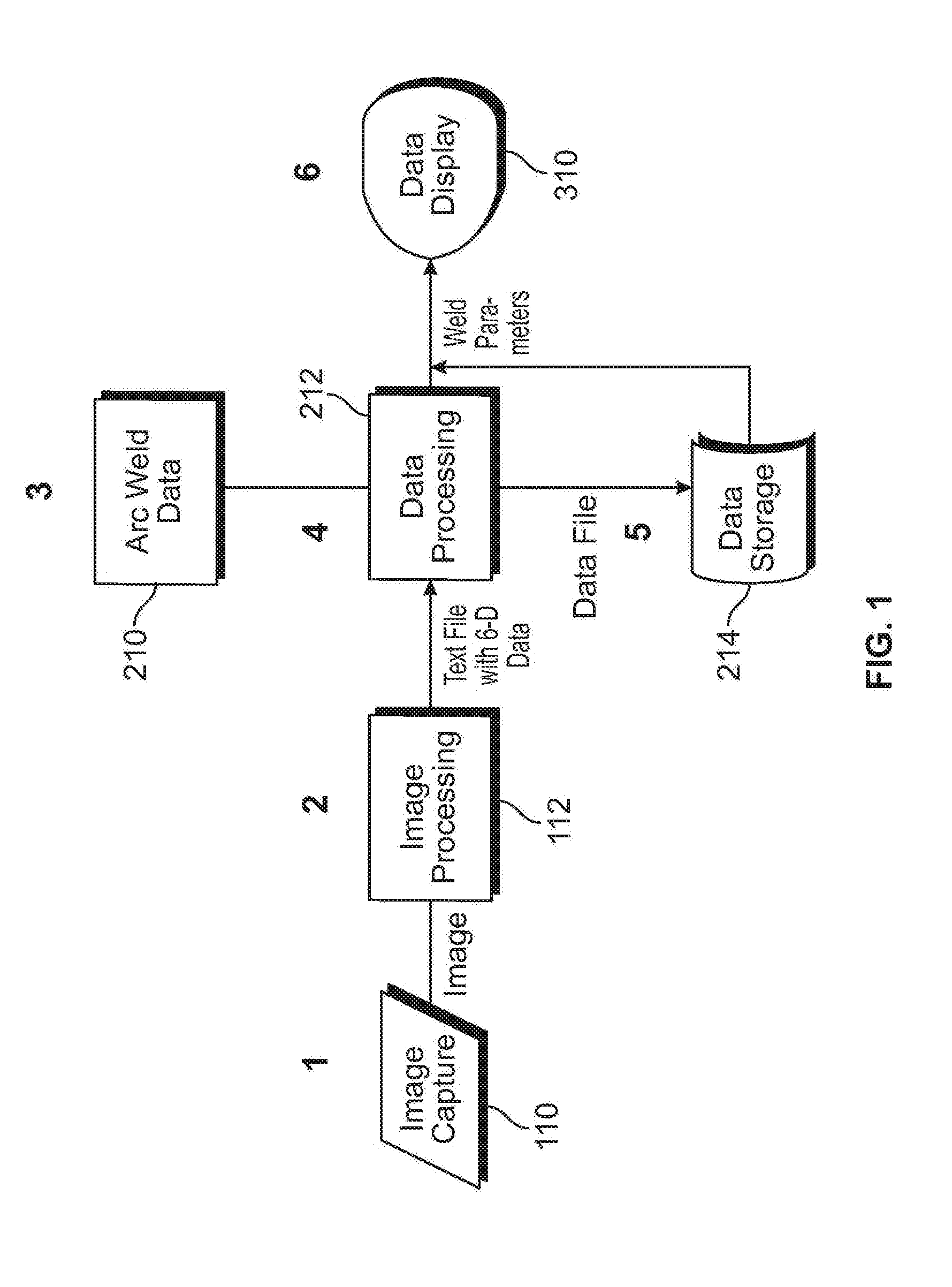
[0024] As shown in FIG. 1, in an exemplary embodiment of the present invention, the basic flow of information through data generating component 100, data capturing component 200, and data processing (and visualization) component 300 of weld characterization system 10 occurs in six basic steps: (1) image capture 110; (2) image processing 112; (3) input of arc weld data 210, such as known or preferred weld parameters; (4) data processing 212; (5) data storage 214; and (5) data display 310. Image capture step 110 includes capturing images of target 98 (which typically includes at least two point markers located in a fixed geometric relationship to one another) with one or more off-the shelf high-speed-vision cameras, where the output aspect typically includes creating of an image file at over 100 frames per second. The input aspect of image processing step 112 includes frame-by-frame point cloud analysis of a rigid body that includes three or more point markets (i.e., the calibrated target). Upon recognition of a known rigid body, position and orientation are calculated relative to the camera origin and the "trained" rigid body orientation. Capturing and comparing the images from two or more cameras allows for a substantially accurate determination of the rigid body position and orientation in three-dimensional space. Images are typically processed at a rate of more than 10 times per second. The output aspect of image processing step 112 includes creation of a data array that includes x-axis, y-axis, and z-axis positional data and roll, pitch, and yaw orientation data, as well as time stamps and software flags. The text file may be streamed or sent at a desired frequency. The input aspect of data processing step 212 includes raw positional and orientation data typically requested at a predetermined rate, while the output aspect includes transforming this raw data into useful welding parameters with algorithms specific to a selected process and joint type. The input aspect of data storage step 214 includes storing welding trial data as a *.dat file, while the output aspect includes saving the data for review and tracking, saving the date for review on a monitor at a later time, and/or reviewing the progress of the student at a later time. Student progress may include total practice time, total arc time, total arc starts, and individual parameter-specific performance over time. The input aspect of data display step 310 includes welding trial data that further includes work angle, travel angle, tool standoff, travel speed, bead placement, weave, voltage, current, wire-feed speed, while the output aspect involves data that may viewed on a monitor, in-helmet display, heads-up display, or combinations thereof, wherein parameters are plotted on a time-based axis and compared to upper and lower thresholds or preferred variations, such as those trained by recording the motions of an expert welder. Current and voltage may be measured in conjunction with travel speed to determine heat input and the welding process parameters may be used to estimate arc length. Position data may be transformed into weld start position, weld stop position, weld length, weld sequence, welding progression, or combinations thereof and current and voltage may be measured in conjunction with travel speed to determine heat input.
[0025] FIGS. 2-5 provide illustrative views of weld characterization system 10 in accordance with an exemplary embodiment the present invention. As shown in FIG. 2, portable training stand 20 includes a substantially flat base 22 for contact with a floor or other horizontal substrate, rigid vertical support column 24, camera or imaging device support 26, and rack and pinion assembly 31 for adjusting the height of imaging device support 26. In most embodiments, weld characterization system 10 is intended to be portable or at least moveable from one location to another, therefore the overall footprint of base 22 is relatively small to permit maximum flexibility with regard to installation and use. As shown in FIG. 2-6, weld characterization system 10 may be used for training exercises that include flat, horizontally or vertically oriented workpieces. In the exemplary embodiments shown in the Figures, training stand 20 is depicted as a unitary or integrated structure that is capable of supporting the other components of system. In other embodiments, stand 20 is absent and the various components of the system are supported by whatever suitable structural or supportive means may be available. Thus, within the context of this invention, "stand" 20 is defined as any single structure or, alternately, multiple structures that are capable of supporting the components of weld characterization system 10.
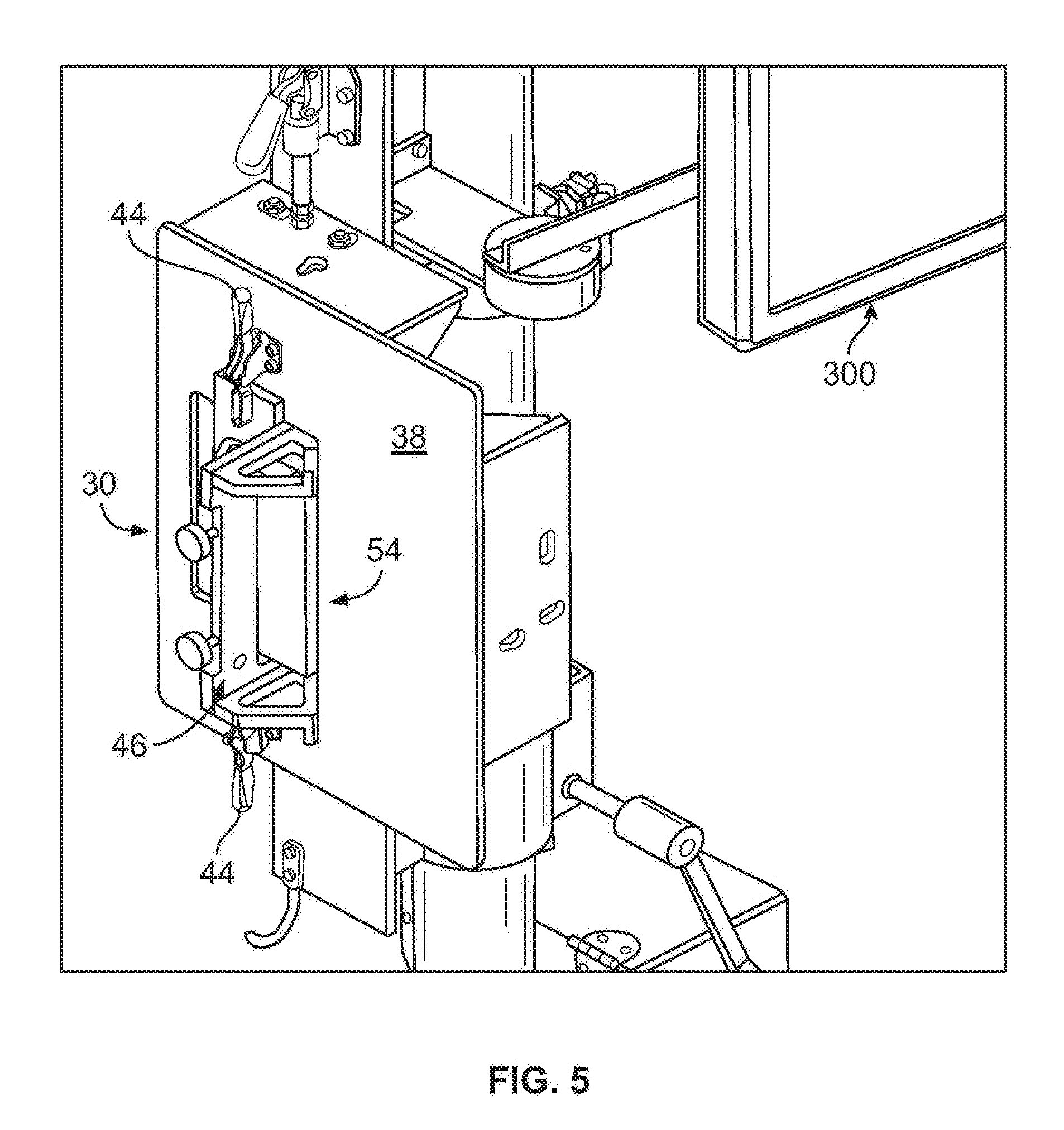
[0026] With to FIGS. 2-3, certain welding exercises will utilize a flat assembly 30, which is slidably attached to vertical support column 24 by collar 34, which slides upward or downward on support column 24. Collar 34 is further supported on column 24 by rack and pinion 31, which includes shaft 32 for moving rack and pinion assembly 31 upward or downward on support column 24. Flat assembly 30 includes training platform 38, which is supported by one or more brackets (not visible). In some embodiments, a shield 42 is attached to training platform 38 for protecting the surface of support column 24 from heat damage. Training platform 38 further includes at least one clamp 44 for securing weld position-specific fixture/jig 46 to the surface of the training platform. The structural configuration or general characteristics of weld position-specific jig 46 are variable based on the type of weld process that is the subject of a particular welding exercise, and in FIGS. 2-3, fixture 46 is configured for a fillet weld exercise. In the exemplary embodiment shown in FIGS. 2-3, first 48 and second 50 structural components of weld position-specific fixture 46 are set at right angles to one another. Position-specific fixture 46 may include one or more pegs 47 for facilitating proper placement of a weld coupon on the fixture. The characteristics of any weld coupon (workpiece) 54 used with system 10 are variable based on the type of manual welding process that is the subject of a particular training exercise and in the exemplary embodiment shown in the FIGS. 7-8, first 56 and second 58 portions of weld coupon 54 are also set at right angles to one another. With reference to FIGS. 4-5, certain other welding exercises will utilize a horizontal assembly 30 (see FIG. 4) or a vertical assembly 30 (see FIG. 5). In FIG. 4, horizontal assembly 30 supports butt fixture 46, which holds workpiece 54 in the proper position for a butt weld exercise. In FIG. 5, vertical assembly 30 supports vertical fixture 46, which holds workpiece 54 in the proper position for a lap weld exercise.
[0027] Data processing component 300 of the present invention typically includes at least one computer for receiving and analyzing information captured by the data capturing component 200, which itself includes at least one digital camera contained in a protective housing. During operation of weld characterization system 10, this computer is typically running software that includes a training regimen module, an image processing and rigid body analysis module, and a data processing module. The training regimen module includes a variety of weld types and a series of acceptable welding process parameters associated with creating each weld type. Any number of known or AWS weld joint types and the acceptable parameters associated with these weld joint types may be included in the training regimen module, which is accessed and configured by a course instructor prior to the beginning of a training exercise. The weld process and/or type selected by the instructor determine which weld process-specific fixture, calibration device, and weld coupon are used for any given training exercise. The object recognition module is operative to train the system to recognize a known rigid body target 98 (which includes two or more point markers) and for then to use target 98 to calculate positional and orientation data for welding gun 90 as an actual manual weld is completed by a trainee. The data processing module compares the information in the training regimen module to the information processed by the object recognition module and outputs the comparative data to a display device such as a monitor or head-up display. The monitor allows the trainee to visualize the processed data in real time and the visualized data is operative to provide the trainee with useful feedback regarding the characteristics and quality of the weld. The visual interface of weld characterization system 10 may include a variety of features related to the input of information, login, setup, calibration, practice, analysis, and progress tracking. The analysis screen typically displays the welding parameters found in the training regimen module, including (but not limited to) work angle, travel angle, tool standoff, travel speed, bead placement, weave, voltage, current, wire-feed speed, and arc length. Multiple display variations are possible with the present invention.
[0028] In most, if not all instances, weld characterization system 10 will be subjected to a series of calibration steps/processes prior to use. Some of the aspects of the system calibration will typically be performed by the manufacturer of system 10 prior to delivery to a customer and other aspects of the system calibration will typically be performed by the user of weld characterization system 10 prior to any welding training exercises. System calibration typically involves two related and integral calibration processes: (i) determining the three-dimensional position and orientation of the operation path to be created on a workpiece for each joint/position combination to be used in various welding training exercises; and (ii) determining the three-dimensional position and orientation of the welding tool by calculating the relationship between a plurality of reflective (passive) or light emitting (active) point markers located on target 98 and at least two key points represented by point markers located on the welding tool 90.
[0029] The first calibration aspect of this invention typically involves the calibration of the welding operation with respect to the global coordinate system, i.e., relative to the other structural components of weld characterization system 10 and the three-dimensional space occupied thereby. Prior to tracking/characterizing a manual welding exercise, the global coordinates of each desired operation path (i.e., vector) on any given workpiece will be determined. In most embodiments, this is a factory-executed calibration process that will include corresponding configuration files stored on data processing component 200. To obtain the desired vectors, a calibration device containing active or passive markers may be inserted on at least two locating markers in each of the three possible platform positions (i.e., flat, horizontal, and vertical). FIGS. 6-8 illustrate this calibration step in one possible platform position. Joint-specific fixture 46 includes first and second structural components 48 (horizontal) and 50 (vertical), respectively. Weld coupon or workpiece 54 includes first and second portions 56 (horizontal) and 58 (vertical), respectively. Workpiece operation path 59 extends from point X to point Y and is shown in broken line in FIG. 7. Locating point markers 530 and 532 are placed as shown in FIG. 6 (and FIG. 8) and the location of each marker is obtained using data capturing component 100, which in this embodiment utilizes Optitrack Tracking Tools (NaturalPoint, Inc.) or a similar commercially available or proprietary hardware/software system that provides three-dimensional marker and six degrees of freedom object motion tracking in real time. Such technologies typically utilize reflective and/or light emitting point markers arranged in predetermined patterns to create point clouds that are interpreted by system imaging hardware and system software as "rigid bodies", although other suitable methodologies are compatible with this invention.
[0030] In the calibration process represented by the flowchart of FIG. 9, table 38 is fixed into position i (0,1,2) at step 280; a calibration device is placed on locating pins at step 282; all marker positions are captured at step 284; coordinates for the locator positions are calculated at step 286; coordinates for the fillet operation path are calculated at step 288 and stored at 290; coordinates for the lap operation path are calculated at step 292 and stored at 294; and coordinates for the groove operation path are calculated at step 296 and stored at 298. All coordinates are calculated relative to the three dimensional space viewable by data capturing component 200.
[0031] In one embodiment of this invention, the position and orientation of the work-piece is calibrated through the application of two or more passive or active point markers to a calibration device that is placed at a known translational and rotational offset to a fixture that holds the work-piece at a known translational and rotational offset. In another embodiment of this invention, the position and orientation of the work-piece is calibrated through the application of two or more passive or active point markers to a fixture that holds the work-piece at a known translational and rotational offset. In still other embodiments, the workpiece is non-linear, and the position and orientation thereof may be mapped using a calibration tool with two or more passive or active point markers and stored for later use. The position and orientation of the work-piece operation path may undergo a pre-determined translational and rotational offset from its original calibration plane based on the sequence steps in the overall work operation.
[0032] Important tool manipulation parameters such as position, orientation, velocity, acceleration, and spatial relationship to the work-piece operation path may be determined from the analysis of consecutive tool positions and orientations over time and the various work-piece operation paths described above. Tool manipulation parameters may be compared with pre-determined preferred values to determine deviations from known and preferred procedures. Tool manipulation parameters may also combined with other manufacturing process parameters to determine deviations from preferred procedures and these deviations may be used for assessing skill level, providing feedback for training, assessing progress toward a skill goal, or for quality control purposes. Recorded motion parameters relative to the workpiece operation path may be aggregated from multiple operations for statistical process control purposes. Deviations from preferred procedures may be aggregated from multiple operations for statistical process control purposes. Important tool manipulation parameters and tool positions and orientations with respect to the workpiece operation path may also be recorded for establishing a signature of an experienced operator's motions to be used as a baseline for assessing compliance with preferred procedures.
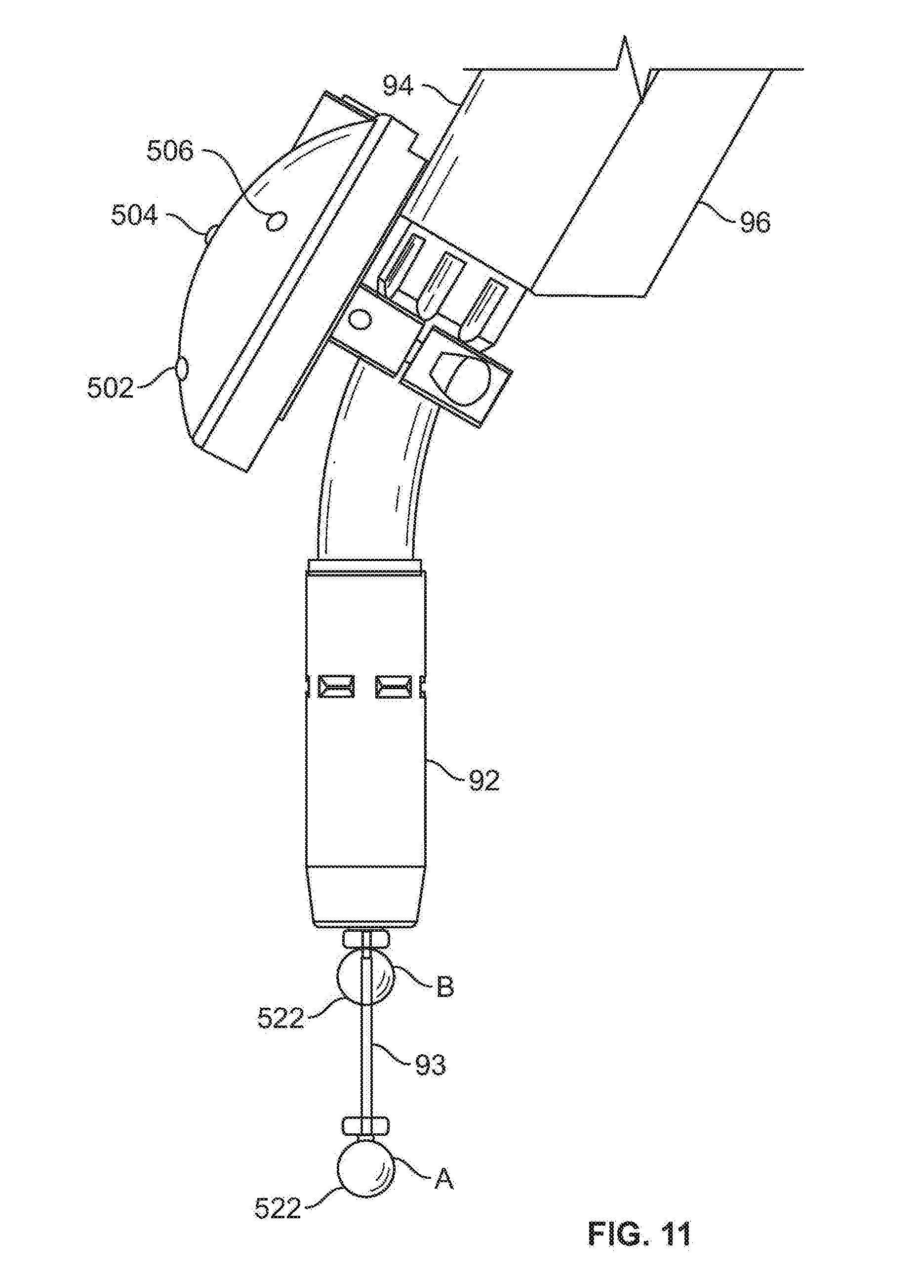
[0033] The second calibration aspect typically involves the calibration of welding tool 90 with respect to target 98. "Welding" tool 90 is typically a welding torch or gun or SMAW electrode holder, but may also be any number of other implements including a soldering iron, cutting torch, forming tool, material removal tool, paint gun, or wrench. With reference to FIGS. 10-11, welding gun/tool 90 includes tool point 91, nozzle 92, body 94, trigger 96, and target 98. Tool calibration device 93, which includes two integrated active or passive point markers in the A and B positions (see FIG. 11) is attached to or inserted into nozzle 92. A rigid body point cloud (i.e., a "rigid body") is constructed by attaching active or passive point markers 502, 504, and 506 (and additional point markers) to the upper surface of target 98 (other placements are possible). Target 98 may include a power input if the point markers used are active and require a power source. Data capturing component 200 uses Optitrack Tracking Tools (NaturalPoint, Inc.) or similar hardware/software to locate the rigid body and point markers 522 (A) and 520 (B), which represent the location of tool vector 524. These positions can be extracted from the software of system 10 and the relationship between point markers A and B and the rigid body can be calculated.
[0034] In the calibration process represented by the flowchart of FIG. 12, weld nozzle 92 and the contact tube are removed at step 250; the calibration device is inserted into body 94 at step 252; weld tool 90 is placed in the working envelope and rigid body 500 (designated as "S" in FIG. 11) and point markers A and B are captured by data capturing component 100; the relationships between A and S and B and S are calculated at step 256; relationship data for As is stored at 258; and relationship data for Bs is stored at 260.
[0035] In one embodiment of this invention, calibration of the tool point and tool vector is performed through the application of two or more passive or active point markers to the calibration device at locations along the tool vector with a known offset to the tool point. In another embodiment, calibration of the tool point and tool vector is performed by inserting the tool into a calibration block of known position and orientation relative to the work-piece. With regard to the rigid body defined by the point markers (e.g., 502, 504, 506), in one embodiment, the passive or active point markers are affixed to the tool in in a multi-faceted manner so that a wide range of rotation and orientation changes can be accommodated within the field of view of the imaging system. In another embodiment, the passive or active point markers are affixed to the tool in a spherical manner so that a wide range of rotation and orientation changes can be accommodated within the field of view of the imaging system. In still another embodiment, the passive or active point markers are affixed to the tool in a ring shape so that a wide range of rotation and orientation changes can be accommodated within the field of view of the imaging system.
[0036] Numerous additional useful features may be incorporated into the present invention. For example, for purposes of image filtering, band-pass or high-pass filters may be incorporated into the optical sequence for each of the plurality of digital cameras in data capturing component 200 for permitting light from only the wavelengths which are reflected or emitted from the point markers to improve image signal-to-noise ratio. Spurious data may be rejected by analyzing only image information obtained from within a dynamic region of interest having a limited offset from a previously known rigid-body locality. This dynamic region of interest may be incorporated into or otherwise predefined (i.e., preprogrammed as a box or region of width x and height y and centered on known positions of target 98) within the field of view of each digital camera such that image information is only processed from this predefined region. The region of interest will change as the rigid body moves and is therefore based on previously known locations of the rigid body. This approach allows the imaging system to view only pixels within the dynamic region of interest when searching for point markers while disregarding or blocking pixels in the larger image frame that are not included in the dynamic region of interest. Decreased processing time is a benefit of this aspect of the invention.
[0037] While the present invention has been illustrated by the description of exemplary embodiments thereof, and while the embodiments have been described in certain detail, it is not the intention of the Applicant to restrict or in any way limit the scope of the appended claims to such detail. Additional advantages and modifications will readily appear to those skilled in the art. Therefore, the invention in its broader aspects is not limited to any of the specific details, representative devices and methods, and/or illustrative examples shown and described. Accordingly, departures may be made from such details without departing from the spirit or scope of the applicant's general inventive concept.
* * * * *
D00000
D00001
D00002
D00003
D00004
D00005
D00006
D00007
D00008
D00009
D00010
D00011
XML
uspto.report is an independent third-party trademark research tool that is not affiliated, endorsed, or sponsored by the United States Patent and Trademark Office (USPTO) or any other governmental organization. The information provided by uspto.report is based on publicly available data at the time of writing and is intended for informational purposes only.
While we strive to provide accurate and up-to-date information, we do not guarantee the accuracy, completeness, reliability, or suitability of the information displayed on this site. The use of this site is at your own risk. Any reliance you place on such information is therefore strictly at your own risk.
All official trademark data, including owner information, should be verified by visiting the official USPTO website at www.uspto.gov. This site is not intended to replace professional legal advice and should not be used as a substitute for consulting with a legal professional who is knowledgeable about trademark law.