Varied Geometry Heat Exchanger Systems And Methods
Stockton; Kevin R. ; et al.
U.S. patent application number 15/968548 was filed with the patent office on 2019-09-26 for varied geometry heat exchanger systems and methods. The applicant listed for this patent is Johnson Controls Technology Company. Invention is credited to Douglas A. Kester, Stacy S. Lemkelde, Nicholas P. Mislak, Ryan L. Snider, Kevin R. Stockton, Kristen Velez-Diaz.
| Application Number | 20190293364 15/968548 |
| Document ID | / |
| Family ID | 67983531 |
| Filed Date | 2019-09-26 |


| United States Patent Application | 20190293364 |
| Kind Code | A1 |
| Stockton; Kevin R. ; et al. | September 26, 2019 |
VARIED GEOMETRY HEAT EXCHANGER SYSTEMS AND METHODS
Abstract
The present disclosure relates to a heat exchanger including a tube having a length, and a cross-sectional geometry defined by an inner boundary and an outer boundary extending along the length. The tube is configured to flow a refrigerant fluid within the inner boundary to transfer heat. The cross-sectional geometry varies at respective transition points along the length of the tube. The tube is seamless and undeformed at the transition points.
| Inventors: | Stockton; Kevin R.; (York, PA) ; Mislak; Nicholas P.; (Bel Air, MD) ; Kester; Douglas A.; (York, PA) ; Snider; Ryan L.; (York, PA) ; Lemkelde; Stacy S.; (York, PA) ; Velez-Diaz; Kristen; (York, PA) | ||||||||||
| Applicant: |
|
||||||||||
|---|---|---|---|---|---|---|---|---|---|---|---|
| Family ID: | 67983531 | ||||||||||
| Appl. No.: | 15/968548 | ||||||||||
| Filed: | May 1, 2018 |
Related U.S. Patent Documents
| Application Number | Filing Date | Patent Number | ||
|---|---|---|---|---|
| 62646789 | Mar 22, 2018 | |||
| Current U.S. Class: | 1/1 |
| Current CPC Class: | F28F 2215/04 20130101; F28F 1/025 20130101; F28D 1/0478 20130101; F28F 1/24 20130101; F28F 1/40 20130101 |
| International Class: | F28F 1/02 20060101 F28F001/02; F28F 1/40 20060101 F28F001/40; F28F 1/24 20060101 F28F001/24 |
Claims
1. A heat exchanger, comprising: a tube having a length, and a cross-sectional geometry defined by an inner boundary and an outer boundary extending along the length, wherein the tube is configured to flow a refrigerant fluid within the inner boundary to transfer heat, wherein the cross-sectional geometry varies at respective transition points along the length of the tube, and wherein the tube is seamless and undeformed at the transition points.
2. The heat exchanger of claim 1, wherein the inner boundary on either side of a transition point is selected from two of the group comprising: a circular profile, an elliptical profile, a raindrop profile, an airfoil profile, a lens profile, a trapezoidal profile, a star profile, and any two of the foregoing that may vary in size or dimension.
3. The heat exchanger of claim 1, wherein the inner boundary of the tube comprises ridges successively arranged about an interior surface of the tube along the length.
4. The heat exchanger of claim 1, wherein the outer boundary has fins at the transition points.
5. The heat exchanger of claim 2, wherein the inner boundary and the outer boundary of the cross-sectional geometry have different profiles.
6. The heat exchanger of claim 1, wherein the tube has an inlet at one end of its length and an outlet at an opposing end of its length, and wherein the inlet and the outlet each have a different cross-sectional geometry.
7. The heat exchanger of claim 1, wherein the tube is formed of a metal.
8. The heat exchanger of claim 7, wherein the metal is aluminum.
9. The heat exchanger of claim 7, wherein the metal is copper.
10. The heat exchanger of claim 1, wherein the cross-sectional geometry at different locations along the length of the tube is based upon characteristics of the refrigerant fluid at the different locations.
11. The heat exchanger of claim 1, wherein the tube comprises fins having varying shapes along the length.
12. The heat exchanger of claim 11, wherein the respective shape of each fin is based upon the characteristics of the refrigerant fluid at that location.
13. The heat exchanger of claim 1, wherein the seamless and undeformed tube is additively formed.
14. A heat exchanger, comprising: a tube configured to flow a fluid therein to transfer heat, wherein a cross-sectional geometry of the tube varies along a length of the tube, and an inner boundary of the cross-sectional geometry of the tube at a point along the length of the tube corresponds with fluid characteristics of the fluid at the point.
15. The heat exchanger of claim 14, wherein the tube comprises a plurality of fins additively integrated with the tube, wherein each fin of the plurality of fins comprises a respective geometry associated with a respective set of flow characteristics of a second fluid configured to pass across the heat exchanger at a respective location of the heat exchanger having the respective fin.
16. The heat exchanger of claim 15, wherein the tube and the plurality of fins comprise additively formed metal.
17. The heat exchanger of claim 16, wherein the additively formed metal comprises aluminum, copper, stainless steel, or titanium.
18. The heat exchanger of claim 14, wherein the cross-sectional geometry comprises an outer boundary of the tube, and the outer boundary of the tube at the point along the length of the tube corresponds with fluid characteristics of a second fluid configured to flow across the tube at the point.
19. The heat exchanger of claim 14, wherein the heat exchanger comprises a plurality of sections, wherein each section of the plurality of sections is associated with a set of fluid characteristics associated with a flow of the first fluid through the tube in the respective section, wherein each section comprises a respective cross-sectional geometry of the tube that is substantially uniform within the respective section, and wherein the respective cross-sectional geometry of the tube is based at least in part on the respective set of fluid characteristics associated with the flow of the first fluid through the tube in the respective section of the plurality of sections.
20. The heat exchanger of claim 14, wherein the cross-sectional geometry comprises a raindrop shape, an airfoil shape, an ellipse shape, a lens shape, a star shape, a trapezoid shape, or any combination thereof.
21. A heat exchanger, comprising: a tube configured to flow a first fluid therein to transfer heat, wherein a cross-sectional geometry of the tube varies along a length of the tube, the cross-sectional geometry comprises an outer boundary of the tube, and the outer boundary of the tube at a point along the length of the tube corresponds with fluid characteristics of a second fluid configured to pass across the tube at the point.
22. The heat exchanger of claim 21, wherein the cross-sectional geometry comprises an inner boundary of the tube, and the inner boundary of the tube at the point along the length of the tube corresponds with fluid characteristics of the first fluid configured to flow through the tube at the point.
23. The heat exchanger of claim 21, wherein the tube comprises a plurality of fins additively integrated with the tube, wherein each fin of the plurality of fins comprises a respective geometry associated with a respective set of flow characteristics of a gas configured to pass across the heat exchanger at a respective location of the heat exchanger having the respective fin.
24. The heat exchanger of claim 21, wherein the cross-sectional geometry of the tube comprises a raindrop shape, an airfoil shape, an ellipse shape, a lens shape, a star shape, a trapezoid shape, or any combination thereof.
25. The heat exchanger of claim 21, wherein the tube of the heat exchanger is formed via additive manufacturing.
26. A method of manufacturing a heat exchanger, comprising: determining fluid characteristics of a heat exchanger, wherein the fluid characteristics comprise flow characteristics of a fluid flowing through a tube of the heat exchanger and flow characteristics of a gas flowing across the tube and fins of the heat exchanger; varying a cross-sectional geometry of the tube of the heat exchanger based at least in part on the flow characteristics of the fluid flowing through the tube of the heat exchanger; and manufacturing the tube via additive manufacturing to incorporate the varying cross-sectional geometry.
27. The method of claim 26, comprising varying geometry of the fins of the heat exchanger based at least in part on the flow characteristics of the gas flowing across the tube and fins of the heat exchanger and manufacturing the fins to incorporate the varying geometry of the fins.
28. The method of claim 26, wherein the fluid characteristics comprise pressure data, temperature data, velocity data, fluid phase data, and fluid turbulence data, or any combination thereof associated with the fluid flowing through the tube and/or the gas flowing across the tube and the fins.
Description
CROSS REFERENCE TO RELATED APPLICATION
[0001] This application is a Non-Provisional Application claiming priority to U.S. Provisional Application No. 62/646,789, entitled "VARIED GEOMETRY HEAT EXCHANGER SYSTEMS AND METHODS," filed Mar. 22, 2018, which is hereby incorporated by reference in its entirety for all purposes.
BACKGROUND
[0002] The present disclosure relates generally to heating, ventilating, and air conditioning systems. A wide range of applications exist for heating, ventilating, and air conditioning (HVAC) systems. For example, residential, light commercial, commercial, and industrial systems are used to control temperatures and air quality in residences and buildings. Such systems often are dedicated to either heating or cooling, although systems are common that perform both of these functions. Very generally, these systems operate by implementing a thermal cycle in which fluids are heated and cooled to provide the desired temperature in a controlled space, typically the inside of a residence or building. Similar systems are used for vehicle heating and cooling, and as well as for general refrigeration. In many HVAC systems, an HVAC system may utilize fins and tubes in a heat exchanger. Such heat exchangers may be manufactured from multiple components, which may result in certain design limitations, such as uniform fin and tube geometries.
SUMMARY
[0003] The present disclosure relates to a heat exchanger including a tube having a length, and a cross-sectional geometry defined by an inner boundary and an outer boundary extending along the length. The tube is configured to flow a refrigerant fluid within the inner boundary to transfer heat. The cross-sectional geometry varies at respective transition points along the length of the tube. The tube is seamless and undeformed at the transition points.
[0004] The present disclosure also relates to a heat exchanger having a tube configured to flow a fluid therein to transfer heat. A cross-sectional geometry of the tube varies along a length of the tube, and an inner boundary of the cross-sectional geometry of the tube at a point along the length of the tube corresponds with fluid characteristics of the fluid at the point.
[0005] The present disclosure further relates to a heat exchanger including a tube configured to flow a first fluid therein to transfer heat. A cross-sectional geometry of the tube varies along a length of the tube, the cross-sectional geometry includes an outer boundary of the tube, and the outer boundary of the tube at a point along the length of the tube corresponds with fluid characteristics of a second fluid configured to pass across the tube at the point.
[0006] The present disclosure further relates to a method of manufacturing a heat exchanger, including determining fluid characteristics of a heat exchanger. The fluid characteristics include flow characteristics of a fluid flowing through a tube of the heat exchanger and flow characteristics of a gas flowing across the tube and fins of the heat exchanger. The method also includes varying a cross-sectional geometry of the tube of the heat exchanger based at least in part on the flow characteristics of the fluid flowing through the tube of the heat exchanger and manufacturing the tube via additive manufacturing to incorporate the varying cross-sectional geometry.
DRAWINGS
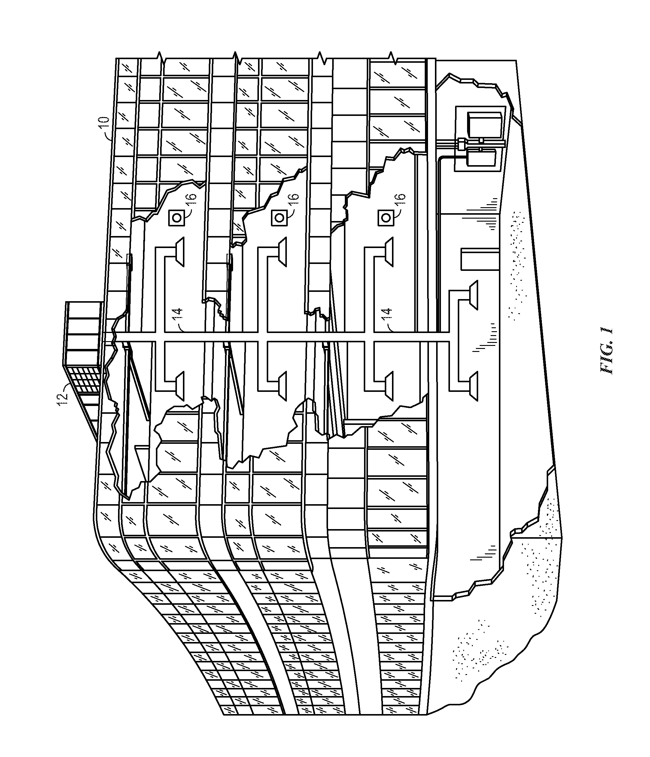
[0007] FIG. 1 is a perspective view of a heating, ventilating, and air conditioning (HVAC) system for building environmental management that may employ one or more HVAC units, in accordance with an embodiment of the present disclosure;
[0008] FIG. 2 is a perspective view of an HVAC unit of the HVAC system of FIG. 1, in accordance with an embodiment of the present disclosure;
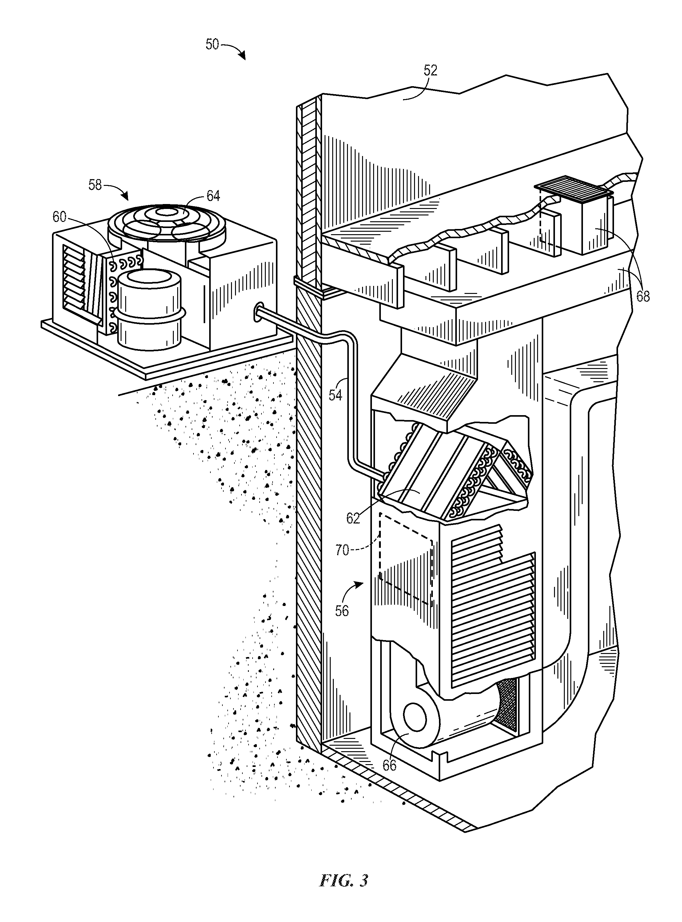
[0009] FIG. 3 is a perspective view of a residential split heating and cooling system, in accordance with an embodiment of the present disclosure;
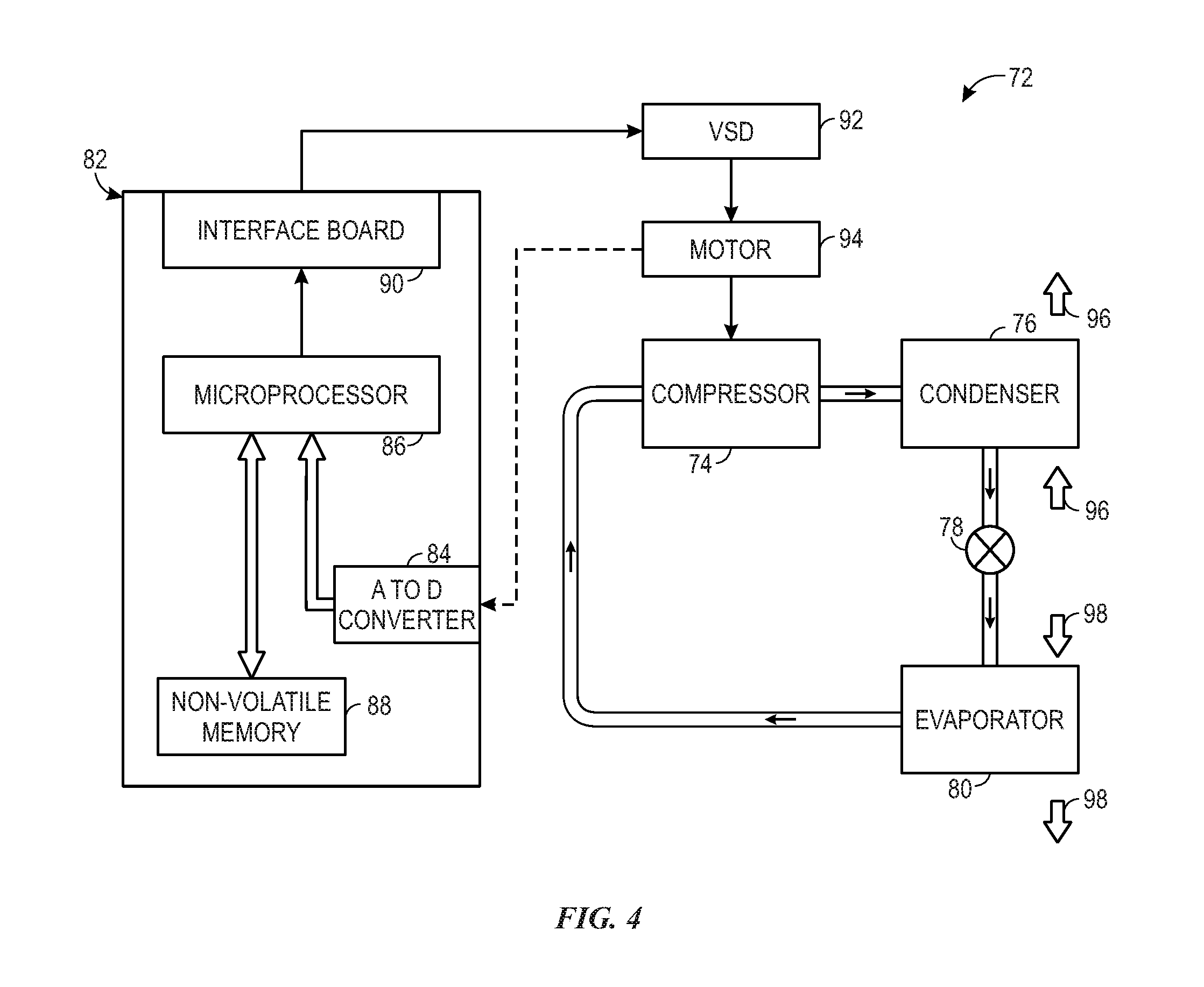
[0010] FIG. 4 is a schematic view of a vapor compression system that may be used in an HVAC system, in accordance with an embodiment of the present disclosure;
[0011] FIG. 5 is a schematic view of a heat exchanger that may be used within the HVAC system of FIG. 1, in accordance with an embodiment of the present disclosure;
[0012] FIG. 6 is a schematic view of a heat exchanger that may be used within the HVAC system of FIG. 1, in accordance with an embodiment of the present disclosure;
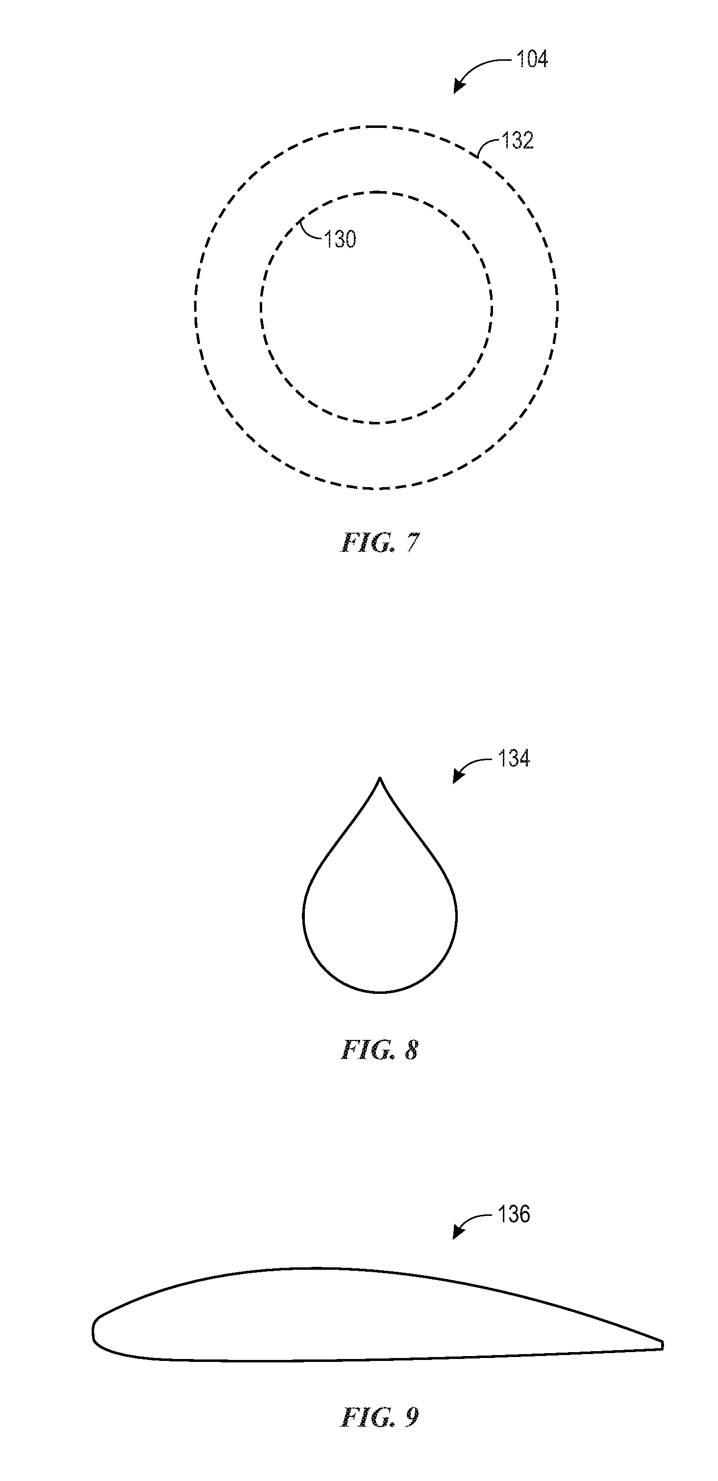
[0013] FIG. 7 is a schematic view of a tube that may be used within the heat exchanger of FIGS. 5 and 6, in accordance with an embodiment of the present disclosure; and
[0014] FIG. 8 is a view of a geometric profile that may form part of the tube of FIG. 7, in accordance with an embodiment of the present disclosure;
[0015] FIG. 9 is a view of a geometric profile that may form part of the tube of FIG. 7, in accordance with an embodiment of the present disclosure;
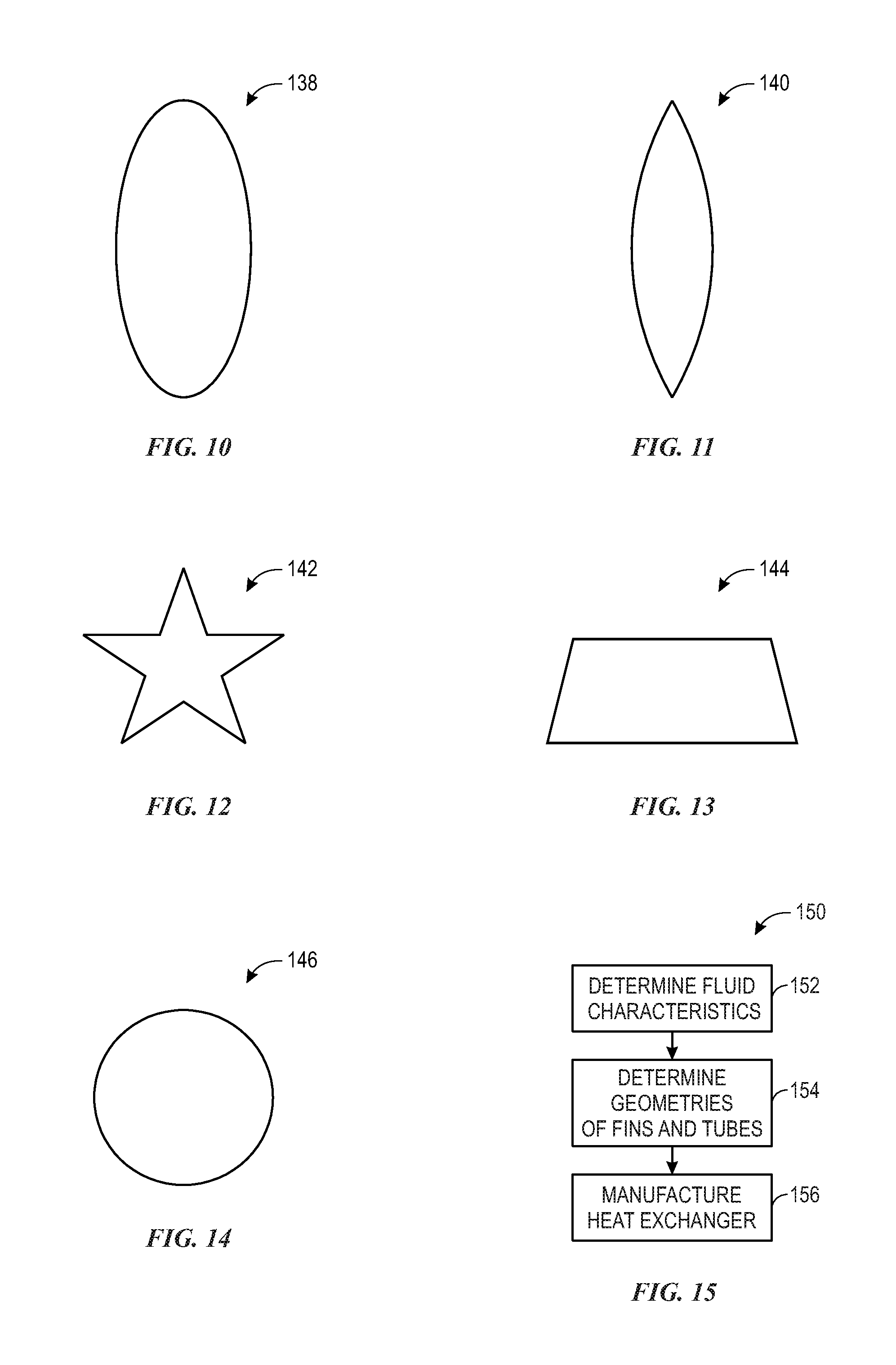
[0016] FIG. 10 is a view of a geometric profile that may form part of the tube of FIG. 7, in accordance with an embodiment of the present disclosure;
[0017] FIG. 11 is a view of a geometric profile that may form part of the tube of FIG. 7, in accordance with an embodiment of the present disclosure;
[0018] FIG. 12 is a view of a geometric profile that may form part of the tube of FIG. 7, in accordance with an embodiment of the present disclosure;
[0019] FIG. 13 is a view of a geometric profile that may form part of the tube of FIG. 7, in accordance with an embodiment of the present disclosure;
[0020] FIG. 14 is a view of a geometric profile that may form part of the tube of FIG. 7, in accordance with an embodiment of the present disclosure; and
[0021] FIG. 15 is a flow chart of a process to manufacture the heat exchanger of FIGS. 5 and 6, in accordance with an embodiment of the present disclosure.
DETAILED DESCRIPTION
[0022] The present disclosure is directed to heating, ventilating, and air conditioning (HVAC) systems and units, which may include heat exchangers having tubes and fins with varied geometries. More particularly, the tubes and fins of such heat exchangers may be manufactured utilizing an additive manufacturing process, such as three-dimensional (3D) printing. The additive manufacturing process may provide for heat exchanger to be manufactured as a single piece with varied geometries. A heat exchanger manufactured using the techniques described herein may be formed as a single piece with varied geometries, and the heat exchanger may be seamless and uniformed at transition points of the varied geometries. For example, in some instances, a traditional heat exchanger may experience pressure drops in certain areas or have varied flow velocities, which may result in inefficient heat transfer. However, certain geometries of the tubes and/or fins of the heat exchanger may be varied throughout the heat exchanger according to fluid characteristics to account for the pressure drops and varied flow velocities. Indeed, the geometries of the tubes and fins of the heat exchanger may be designed to account for a pressure, temperature, velocity, phase, turbulence, and other fluid characteristics that may affect heat transfer within the heat exchanger.
[0023] Turning now to the drawings, FIG. 1 illustrates a heating, ventilating, and air conditioning (HVAC) system for building environmental management that may employ one or more HVAC units. In the illustrated embodiment, a building 10 is air conditioned by a system that includes an HVAC unit 12. The building 10 may be a commercial structure or a residential structure. As shown, the HVAC unit 12 is disposed on the roof of the building 10; however, the HVAC unit 12 may be located in other equipment rooms or areas adjacent the building 10. The HVAC unit 12 may be a single package unit containing other equipment, such as a blower, integrated air handler, and/or auxiliary heating unit. In other embodiments, the HVAC unit 12 may be part of a split HVAC system, such as the system shown in FIG. 3, which includes an outdoor HVAC unit 58 and an indoor HVAC unit 56.
[0024] The HVAC unit 12 is an air cooled device that implements a refrigeration cycle to provide conditioned air to the building 10. Specifically, the HVAC unit 12 may include one or more heat exchangers across which an air flow is passed to condition the air flow before the air flow is supplied to the building. In the illustrated embodiment, the HVAC unit 12 is a rooftop unit (RTU) that conditions a supply air stream, such as environmental air and/or a return air flow from the building 10. After the HVAC unit 12 conditions the air, the air is supplied to the building 10 via ductwork 14 extending throughout the building 10 from the HVAC unit 12. For example, the ductwork 14 may extend to various individual floors or other sections of the building 10. In certain embodiments, the HVAC unit 12 may be a heat pump that provides both heating and cooling to the building with one refrigeration circuit configured to operate in different modes. In other embodiments, the HVAC unit 12 may include one or more refrigeration circuits for cooling an air stream and a furnace for heating the air stream.
[0025] A control device 16, one type of which may be a thermostat, may be used to designate the temperature of the conditioned air. The control device 16 also may be used to control the flow of air through the ductwork 14. For example, the control device 16 may be used to regulate operation of one or more components of the HVAC unit 12 or other components, such as dampers and fans, within the building 10 that may control flow of air through and/or from the ductwork 14. In some embodiments, other devices may be included in the system, such as pressure and/or temperature transducers or switches that sense the temperatures and pressures of the supply air, return air, and so forth. Moreover, the control device 16 may include computer systems that are integrated with or separate from other building control or monitoring systems, and even systems that are remote from the building 10.
[0026] FIG. 2 is a perspective view of an embodiment of the HVAC unit 12. In the illustrated embodiment, the HVAC unit 12 is a single package unit that may include one or more independent refrigeration circuits and components that are tested, charged, wired, piped, and ready for installation. The HVAC unit 12 may provide a variety of heating and/or cooling functions, such as cooling only, heating only, cooling with electric heat, cooling with dehumidification, cooling with gas heat, or cooling with a heat pump. As described above, the HVAC unit 12 may directly cool and/or heat an air stream provided to the building 10 to condition a space in the building 10.
[0027] As shown in the illustrated embodiment of FIG. 2, a cabinet 24 encloses the HVAC unit 12 and provides structural support and protection to the internal components from environmental and other contaminants. In some embodiments, the cabinet 24 may be constructed of galvanized steel and insulated with aluminum foil faced insulation. Rails 26 may be joined to the bottom perimeter of the cabinet 24 and provide a foundation for the HVAC unit 12. In certain embodiments, the rails 26 may provide access for a forklift and/or overhead rigging to facilitate installation and/or removal of the HVAC unit 12. In some embodiments, the rails 26 may fit into "curbs" on the roof to enable the HVAC unit 12 to provide air to the ductwork 14 from the bottom of the HVAC unit 12 while blocking elements such as rain from leaking into the building 10.
[0028] The HVAC unit 12 includes heat exchangers 28 and 30 in fluid communication with one or more refrigeration circuits. Tubes within the heat exchangers 28 and 30 may circulate refrigerant, such as R-410A, through the heat exchangers 28 and 30. The tubes may be of various types, such as multichannel tubes, conventional copper or aluminum tubing, and so forth. Together, the heat exchangers 28 and 30 may implement a thermal cycle in which the refrigerant undergoes phase changes and/or temperature changes as it flows through the heat exchangers 28 and 30 to produce heated and/or cooled air. For example, the heat exchanger 28 may function as a condenser where heat is released from the refrigerant to ambient air, and the heat exchanger 30 may function as an evaporator where the refrigerant absorbs heat to cool an air stream. In other embodiments, the HVAC unit 12 may operate in a heat pump mode where the roles of the heat exchangers 28 and 30 may be reversed. That is, the heat exchanger 28 may function as an evaporator and the heat exchanger 30 may function as a condenser. In further embodiments, the HVAC unit 12 may include a furnace for heating the air stream that is supplied to the building 10. While the illustrated embodiment of FIG. 2 shows the HVAC unit 12 having two of the heat exchangers 28 and 30, in other embodiments, the HVAC unit 12 may include one heat exchanger or more than two heat exchangers.
[0029] The heat exchanger 30 is located within a compartment 31 that separates the heat exchanger 30 from the heat exchanger 28. Fans 32 draw air from the environment through the heat exchanger 28. Air may be heated and/or cooled as the air flows through the heat exchanger 28 before being released back to the environment surrounding the rooftop unit 12. A blower assembly 34, powered by a motor 36, draws air through the heat exchanger 30 to heat or cool the air. The heated or cooled air may be directed to the building 10 by the ductwork 14, which may be connected to the HVAC unit 12. Before flowing through the heat exchanger 30, the conditioned air flows through one or more filters 38 that may remove particulates and contaminants from the air. In certain embodiments, the filters 38 may be disposed on the air intake side of the heat exchanger 30 to prevent contaminants from contacting the heat exchanger 30.
[0030] The HVAC unit 12 also may include other equipment for implementing the thermal cycle. Compressors 42 increase the pressure and temperature of the refrigerant before the refrigerant enters the heat exchanger 28. The compressors 42 may be any suitable type of compressors, such as scroll compressors, rotary compressors, screw compressors, or reciprocating compressors. In some embodiments, the compressors 42 may include a pair of hermetic direct drive compressors arranged in a dual stage configuration 44. However, in other embodiments, any number of the compressors 42 may be provided to achieve various stages of heating and/or cooling. As may be appreciated, additional equipment and devices may be included in the HVAC unit 12, such as a solid-core filter drier, a drain pan, a disconnect switch, an economizer, pressure switches, phase monitors, and humidity sensors, among other things.
[0031] The HVAC unit 12 may receive power through a terminal block 46. For example, a high voltage power source may be connected to the terminal block 46 to power the equipment. The operation of the HVAC unit 12 may be governed or regulated by a control board 48. The control board 48 may include control circuitry connected to a thermostat, sensors, and alarms. One or more of these components may be referred to herein separately or collectively as the control device 16. The control circuitry may be configured to control operation of the equipment, provide alarms, and monitor safety switches. Wiring 49 may connect the control board 48 and the terminal block 46 to the equipment of the HVAC unit 12.
[0032] FIG. 3 illustrates a residential heating and cooling system 50, also in accordance with present techniques. The residential heating and cooling system 50 may provide heated and cooled air to a residential structure, as well as provide outside air for ventilation and provide improved indoor air quality (IAQ) through devices such as ultraviolet lights and air filters. In the illustrated embodiment, the residential heating and cooling system 50 is a split HVAC system. In general, a residence 52 conditioned by a split HVAC system may include refrigerant conduits 54 that operatively couple the indoor unit 56 to the outdoor unit 58. The indoor unit 56 may be positioned in a utility room, an attic, a basement, and so forth. The outdoor unit 58 is typically situated adjacent to a side of residence 52 and is covered by a shroud to protect the system components and to prevent leaves and other debris or contaminants from entering the unit. The refrigerant conduits 54 transfer refrigerant between the indoor unit 56 and the outdoor unit 58, typically transferring primarily liquid refrigerant in one direction and primarily vaporized refrigerant in an opposite direction.
[0033] When the system shown in FIG. 3 is operating as an air conditioner, a heat exchanger 60 in the outdoor unit 58 serves as a condenser for re-condensing vaporized refrigerant flowing from the indoor unit 56 to the outdoor unit 58 via one of the refrigerant conduits 54. In these applications, a heat exchanger 62 of the indoor unit functions as an evaporator. Specifically, the heat exchanger 62 receives liquid refrigerant (which may be expanded by an expansion device, not shown) and evaporates the refrigerant before returning it to the outdoor unit 58.
[0034] The outdoor unit 58 draws environmental air through the heat exchanger 60 using a fan 64 and expels the air above the outdoor unit 58. When operating as an air conditioner, the air is heated by the heat exchanger 60 within the outdoor unit 58 and exits the unit at a temperature higher than it entered. The indoor unit 56 includes a blower or fan 66 that directs air through or across the indoor heat exchanger 62, where the air is cooled when the system is operating in air conditioning mode. Thereafter, the air is passed through ductwork 68 that directs the air to the residence 52. The overall system operates to maintain a desired temperature as set by a system controller. When the temperature sensed inside the residence 52 is higher than the set point on the thermostat, or the set point plus a small amount, the residential heating and cooling system 50 may become operative to refrigerate additional air for circulation through the residence 52. When the temperature reaches the set point, or the set point minus a small amount, the residential heating and cooling system 50 may stop the refrigeration cycle temporarily.
[0035] The residential heating and cooling system 50 may also operate as a heat pump. When operating as a heat pump, the roles of heat exchangers 60 and 62 are reversed. That is, the heat exchanger 60 of the outdoor unit 58 will serve as an evaporator to evaporate refrigerant and thereby cool air entering the outdoor unit 58 as the air passes over outdoor the heat exchanger 60. The indoor heat exchanger 62 will receive a stream of air blown over it and will heat the air by condensing the refrigerant.
[0036] In some embodiments, the indoor unit 56 may include a furnace system 70. For example, the indoor unit 56 may include the furnace system 70 when the residential heating and cooling system 50 is not configured to operate as a heat pump. The furnace system 70 may include a burner assembly and heat exchanger, among other components, inside the indoor unit 56. Fuel is provided to the burner assembly of the furnace 70 where it is mixed with air and combusted to form combustion products. The combustion products may pass through tubes or piping in a heat exchanger, separate from heat exchanger 62, such that air directed by the blower 66 passes over the tubes or pipes and extracts heat from the combustion products. The heated air may then be routed from the furnace system 70 to the ductwork 68 for heating the residence 52.
[0037] FIG. 4 is an embodiment of a vapor compression system 72 that can be used in any of the systems described above. The vapor compression system 72 may circulate a refrigerant through a circuit starting with a compressor 74. The circuit may also include a condenser 76, an expansion valve(s) or device(s) 78, and an evaporator 80. The vapor compression system 72 may further include a control panel 82 that has an analog to digital (A/D) converter 84, a microprocessor 86, a non-volatile memory 88, and/or an interface board 90. The control panel 82 and its components may function to regulate operation of the vapor compression system 72 based on feedback from an operator, from sensors of the vapor compression system 72 that detect operating conditions, and so forth.
[0038] In some embodiments, the vapor compression system 72 may use one or more of a variable speed drive (VSDs) 92, a motor 94, the compressor 74, the condenser 76, the expansion valve or device 78, and/or the evaporator 80. The motor 94 may drive the compressor 74 and may be powered by the variable speed drive (VSD) 92. The VSD 92 receives alternating current (AC) power having a particular fixed line voltage and fixed line frequency from an AC power source, and provides power having a variable voltage and frequency to the motor 94. In other embodiments, the motor 94 may be powered directly from an AC or direct current (DC) power source. The motor 94 may include any type of electric motor that can be powered by a VSD or directly from an AC or DC power source, such as a switched reluctance motor, an induction motor, an electronically commutated permanent magnet motor, or another suitable motor.
[0039] The compressor 74 compresses a refrigerant vapor and delivers the vapor to the condenser 76 through a discharge passage. In some embodiments, the compressor 74 may be a centrifugal compressor. The refrigerant vapor delivered by the compressor 74 to the condenser 76 may transfer heat to a fluid passing across the condenser 76, such as ambient or environmental air 96. The refrigerant vapor may condense to a refrigerant liquid in the condenser 76 as a result of thermal heat transfer with the environmental air 96. The liquid refrigerant from the condenser 76 may flow through the expansion device 78 to the evaporator 80.
[0040] The liquid refrigerant delivered to the evaporator 80 may absorb heat from another air stream, such as a supply air stream 98 provided to the building 10 or the residence 52. For example, the supply air stream 98 may include ambient or environmental air, return air from a building, or a combination of the two. The liquid refrigerant in the evaporator 80 may undergo a phase change from the liquid refrigerant to a refrigerant vapor. In this manner, the evaporator 38 may reduce the temperature of the supply air stream 98 via thermal heat transfer with the refrigerant. Thereafter, the vapor refrigerant exits the evaporator 80 and returns to the compressor 74 by a suction line to complete the cycle.
[0041] In some embodiments, the vapor compression system 72 may further include a reheat coil in addition to the evaporator 80. For example, the reheat coil may be positioned downstream of the evaporator relative to the supply air stream 98 and may reheat the supply air stream 98 when the supply air stream 98 is overcooled to remove humidity from the supply air stream 98 before the supply air stream 98 is directed to the building 10 or the residence 52.
[0042] It should be appreciated that any of the features described herein may be incorporated with the HVAC unit 12, the residential heating and cooling system 50, or other HVAC systems. Additionally, while the features disclosed herein are described in the context of embodiments that directly heat and cool a supply air stream provided to a building or other load, embodiments of the present disclosure may be applicable to other HVAC systems as well. For example, the features described herein may be applied to mechanical cooling systems, free cooling systems, chiller systems, or other heat pump or refrigeration applications.
[0043] As discussed below, a heat exchanger, such as the heat exchangers 28 and 30, the condenser 76, and the evaporator 80, may include tubes and fins manufactured as a single integral component. Particularly, a heat exchanger may be manufactured utilizing additive manufacturing techniques to include multiple geometries to account for fluid characteristics within the heat exchanger and increase heat transfer of the heat exchanger. For example, as discussed above, a heat exchanger may include one or more tubes configured to convey a fluid, such as a refrigerant. As the fluid travels through the tube, the fluid may change from a first phase, such as a liquid, to a second phase, such as a gas, or vice versa. Accordingly, fluid properties of the fluid may change as the fluid travels through the tube. To optimize the fluid flow through the tubes, heat exchangers discussed herein may include varying geometries.
[0044] For example, the geometry or cross-sectional profile of a heat exchanger tube may vary along a length of the tube. For example, as mentioned above, the geometry or cross-sectional profile of the tube may change at transition points along the length of the tube, and such changes in geometry may be enabled and formed via additive manufacturing. For example, the transition points along the length of the tube may be seamless and or undeformed from one geometry or cross-sectional profile to another adjacent geometry or cross-sectional profile of the tube. As used herein, a "seamless" and "undeformed" material may refer to a single material formed without a traditional technique, such as by welding, brazing, or friction. For example, the seamless and undeformed material extending from one geometry or cross-sectional profile to another adjacent geometry or cross-sectional profile may have a common grain pattern or structure. For example, as noted above, the seamless and undeformed material may be formed via additive manufacturing. As a result, the tube may have multiple, different geometries or cross-sectional profiles that vary across the length of the tube.
[0045] The selected geometry of the tube at a particular point along the length of the tube may be selected based on expected fluid properties or characteristics of the fluid within the tube at that particular point. In other words, the selected geometry of the tube at a particular point along the length of the tube may correspond with fluid properties of the fluid at the particular point. As an example, in a condenser, a refrigerant may enter tubes of the condenser in a gaseous phase and exit the tubes of the condenser in a liquid phase. Accordingly, the tubes of the condenser at an inlet portion or first section of the tubes may have a selected geometry or cross-sectional profile that is optimized for gaseous refrigerant flow. However, the tubes of the condenser at an outlet or second section of the tube may have a different selected geometry or cross-sectional profile that is optimized for liquid refrigerant flow. Indeed, the tubes of the condenser may include multiple, various geometries along the lengths of the tubes that correspond with expected fluid properties of the fluid passing through the tubes at particular points within the tubes. Similarly, heat exchangers may be manufactured with fins having varying geometries. For example, the selected geometry of a fin at a particular point may be based on or may correspond with expected qualities or characteristics of an air flow passing across the heat exchanger at the particular point. As will be appreciated, utilization of additive manufacturing techniques enable the manufacturing of heat exchangers with such varying geometries, and such vary geometries may be manufactured with seamless and/or undeformed transition points between the varied geometries.
[0046] To illustrate, FIG. 5 is a schematic of a heat exchanger 100 that may be formed through additive manufacturing (AM) to include multiple geometries, where the multiple geometries are seamless and undeformed at transition points between the multiple geometries. For example, the heat exchanger 100 may be formed utilizing vat photopolymerization, material extrusion, material jetting, binder jetting, powder bed fusion, direct energy deposition, sheet lamination, 3D printing, or any other suitable AM process. In this manner, the heat exchanger 100 may be formed as a single, substantially seamless, component. Further, the heat exchanger 100 may be composed of any suitable material that may be AM applicable and conducive to heat transfer such as aluminum, copper, stainless steel, titanium, or any other suitable material.
[0047] In certain embodiments, the heat exchanger 100 may flow a fluid 102, such as water, a water-glycol solution, a refrigerant, or any other suitable fluid, through tubes 104, or coils. The fluid 102 may be put in a heat exchange relationship with a fluid 106, such as air, as the fluid 106 is forced or drawn across the tube 104 and fins 108. Indeed, the fins 108 may be integrally formed around the outer surfaces of the tubes 104 to increase heat transfer between the fluid 102 flowing through the tubes 104 and the fluid 106 flowing over the tubes 104 and the fins 108.
[0048] As discussed herein, the tubes 104 and the fins 108 of the heat exchanger 100 may be manufactured to include a variety of geometries. For example, the tubes 104 may include a variety of cross-sectional shapes, such as raindrop, polygon, airfoil, ellipse, lens, star, trapezoid, or any other suitable shape. The cross-sectional shape of each tube 104 may vary along the respective length of the tube 104. Similarly, the fins 108 may also include a variety of cross-sectional shapes such as polygon, corrugated, curved, or any other suitable shape. Each tube 104 may have fins 108 of varying geometries. For example, the geometry of a particular fan may be selected based on expected flow characteristics of the fluid 106 flowing across the heat exchanger 100 at the location of the fin 108 on the heat exchanger 100. As mentioned above, the heat exchanger 100 may be formed via AM as a single component. Accordingly, the tubes 104 and the fins 108 may transition between various cross-sectional geometries without the use of adaptor fittings, welds, or other secondary coupling elements.
[0049] As mentioned above, the various geometries of the tubes 104 and the fins 108 may depend on fluid characteristics of the fluid 102 and the fluid 106 as they flow through or across the heat exchanger 100. For example, the geometries of the tubes 104 and the fins 108 may depend on a phase, a pressure, a temperature, a flow condition, which may be expressed as a Reynolds number, a velocity, or any other suitable fluid characteristic of the fluid 102 and the fluid 106. Indeed, values of the fluid characteristics of the fluid 102 and the fluid 106 may vary throughout the heat exchanger 100. Accordingly, the geometries of the tubes 104 and the fins 108 may correspond to the fluid characteristics of the fluid 102 and the fluid 106 at respective locations within the heat exchanger 100. That is, certain geometries may be particularly conducive to increasing heat transfer for a first set of fluid characteristics while a second set of geometries may be particularly conducive to increasing heat transfer for a second set of fluid characteristics.
[0050] For example, a certain geometry of the tubes 104 and the fins 108 may provide for a higher rate of heat transfer if the fluid 102 is a liquid, while another geometry may provide for a higher rate of heat transfer if the fluid 102 is a vapor or gas. Further, in certain embodiments, the geometries of the tubes 104 and the fins 108 may provide for substantially equalized face velocity of the fluid 106 across the heat exchanger 100. That is, certain areas of the heat exchanger 100 may have first geometries of the tubes 104 and the fins 108 to increase a face velocity while other areas of the heat exchanger 100 may have second geometries of the tubes 104 and the fins 108 to decrease a face velocity, thereby substantially equalizing a face velocity across the entire heat exchanger 100 and increasing a heat transfer efficiency of the heat exchanger 100.
[0051] To illustrate, FIG. 6 is a schematic view of the heat exchanger 100 with a varied geometry distribution, where the varied geometries are seamless and undeformed at transition points 119 between the multiple geometries. For example, in certain embodiments, the heat exchanger 100 may be divided into multiple sections, each associated with its own unique fluid characteristics. For illustrative purposes, in the current embodiment, the heat exchanger 100 is divided into three areas including a first section 120, a second section 122, and a third section 124. Each of the first, second, and third sections 120, 122, and 124 may be associated with unique fluid characteristics and corresponding geometries of the tubes 104 and the fins 108. However, it is to be understood that in some embodiments, the heat exchanger 100 may be divided into any suitable number of sections, each with its own unique fluid characteristics and geometry.
[0052] As shown, the fluid 106 may generally enter the heat exchanger 100 at or through the second section 122. Accordingly, the second section 122 may generally receive the fluid 106 at a higher speed and/or with a lower pressure drop relative to the first and third sections 120, 124. Therefore, the geometries of the tubes 104 and the fins 108 may be selected to increase a speed and/or decrease a pressure drop of the gas 106 in the first and third sections 120, 124. Additionally, or in the alternative, the geometries of the tubes 104 and the fins 108 may be designed to decrease a speed and/or increase a pressure drop of the fluid 106 in the second section 122. Further, the second section 122 may receive the fluid 106 in a substantially lateral direction 125 while the first and third sections 120, 124 may receive the fluid 106 in an angled direction 127. Accordingly, the second section 122 may include certain geometries of the tubes 104 and the fins 108 that is configured to receive the fluid 106 from the lateral direction 125 to promote heat transfer. In addition, the first and third sections 120, 124 may similarly include certain geometries of the tubes 104 and the fins 108 that is configured to receive the fluid 106 from the angled direction 127 to promote heat transfer. In certain embodiments, pressure, speed, and velocity of the fluid 106 may be due to a blower or fan being positioned such that it pushes or pulls the fluid 106 through the heat exchanger 100 substantially focused within the second section 122. Overall, the geometries of the tubes 104 and the fins 108 may be formed in accordance to a velocity of flow of the fluid 106 to promote heat transfer, such as by reducing pressure drops, equalizing face velocity across the heat exchanger, maximizing surface area, and so forth.
[0053] The fluid 102 may also be associated with differing fluid characteristics and geometries throughout the heat exchanger 100. For example, the fluid 102 may enter the tubes 104 through an inlet 126 and may exit the tubes 104 through an outlet 128. As the fluid 102 enters the inlet 126, the fluid may be associated with a first set of characteristics, and as the fluid 102 exits the outlet 128, the fluid 102 may be associated with a second set of fluid characteristics. For example, a fourth section 121 of the heat exchanger 100 may be associated with a fourth geometry of the tubes 104 and fins 108 that is configured to enhance heat transfer of the fluid 102 and/or the fluid 106 having a fourth set of fluid characteristics, a fifth section 123 of the heat exchanger 100 may be associated with a fifth geometry of the tubes 104 and fins 108 that is configured to enhance heat transfer of the fluid 102 and/or the fluid 106 having a fifth set of fluid characteristics, and a sixth section 125 of the heat exchanger 100 may be associated with a sixth geometry of the tubes 104 and fins 108 that is configured to enhance heat transfer of the fluid 102 and/or the fluid 106 having the sixth set of fluid characteristics.
[0054] As mentioned above, the heat exchanger 100 may be manufactured to include tubes 104 and fins 108 having multiple geometries with seamless and undeformed or substantially seamless and undeformed transition points 119. That is, the transition points 119 may be locations in which the tubes 104 and/or the fins 108 transition between geometries. For example, as shown, the transition points 119 may be located between the sections 120, 121, 122, 123, 124, 125 of the heat exchanger 100, which may each be associated with one or more geometries of the tubes 104 and the fins 108 and fluid characteristics of the fluids 102, 106. As discussed above, "seamless" and "undeformed" may refer to a single material formed without a traditional technique, such as by welding, brazing, or friction. For example, the seamless and undeformed material extending from one geometry or cross-sectional profile to another adjacent geometry or cross-sectional profile may have a common grain pattern or structure. For example, as noted above, the seamless and undeformed material may be formed via additive manufacturing. As a result, the tube may have multiple, different geometries or cross-sectional profiles that vary across the length of the tube.
[0055] FIG. 7 is a schematic cross-sectional view of the tubes 104. As shown, the tubes 104 include an interior geometry 130 and an exterior geometry 132. In the current embodiment, the interior geometry 130 and the exterior geometry 132 are substantially circular. However, as discussed herein, the interior geometry 130 and the exterior geometry 132 may each be uniquely formed to promote heat transfer based on fluid characteristics of the fluid 102 and the fluid 106. For example, the interior geometry 130 may include protrusions, or ridges, to create turbulent flow in the fluid 102 as it flows within the tubes 104, while the exterior geometry 132 may include an airfoil shape to maintain or increase velocity of the fluid 106 as it flows over the tubes 104. In certain embodiments, the interior and/or exterior geometries 130, 132 may include a polygonal shape that is helically shaped, or twisted, along a length of the tubes 104. In other words, the tubes 104 may be helically shaped with a polygonal cross-section, or any other suitably shaped cross-section.
[0056] FIGS. 8-14 are cross-sectional views of geometry profiles that may be included in the interior geometry 130 and/or the exterior geometry 132 of the tubes 104. FIG. 8 is a cross-sectional view of a raindrop profile 134, which may include a pointed end and a round end and may be utilized to direct a flow of fluid and/or increase heat transfer within the heat exchanger 100. FIG. 9 is a cross-sectional view of an airfoil profile 136, which may help to control or improve a direction of flow of fluid across the heat exchanger 100 and may be utilized to increase heat transfer within the heat exchanger 100. FIG. 10 is a cross-sectional view of an ellipse profile 138, which may be utilized to direct or improve a flow of fluid and/or increase heat transfer within or across the heat exchanger 100. FIG. 11 is a cross-sectional view of a lens profile 140, which may be utilized to direct or improve a flow of fluid and/or increase heat transfer within or across the heat exchanger 100. The lens profile 140 may include any suitable lens shape, such as biconvex, biconcave, plano-concave, plano-convex, and/or meniscus. FIG. 12 is a cross-sectional view of a star profile 142, which may be utilized to direct or improve a flow of fluid and/or increase heat transfer within or across the heat exchanger 100. The star profile 142 may have any suitable number of edges and vertices. FIG. 13 is a cross-sectional view of a trapezoidal profile 144, which may be utilized to direct or improve a flow of fluid and/or increase heat transfer within or across the heat exchanger 100. FIG. 14 is a cross-sectional view of a circular profile 146, which may be utilized to direct or improve a flow of fluid and/or increase heat transfer within or across the heat exchanger 100.
[0057] FIG. 15 is a flow chart of a process 150 to manufacture the heat exchanger 100. At block 152, fluid characteristics of the heat exchanger 100 may be determined. That is, phases, pressures, temperatures, flow conditions, velocities, and/or other fluid characteristics of the fluid 106 as it passes across the heat exchanger 100 at various locations of the heat exchanger 100 may be determined. Similarly, phases, pressures, temperatures, flow conditions, velocities, and/or other fluid characteristics of the fluid 102 at various locations along the lengths of the tubes 104 may be determined as it flows through the tubes 104. The fluid characteristics of the fluid 106 and the fluid 102 may be determined through any suitable manner such as through utilization of sensors, such as flow sensors, temperature sensors, flow meters, pressure sensors, or any other suitable sensor or monitoring device. Once the fluid characteristics of the heat exchanger 100 have been determined, the geometries of the tubes 104 and fins 108 may be determined, as indicated by block 154. More particularly, the geometries of the tubes 104 and fins 108 may be determined based on the fluid characteristics of the heat exchanger 100 to enhance the heat transfer capabilities. Indeed, as discussed herein, there may be any suitable number and combinations of the geometries of the tubes 104 and the fins 108 within the heat exchanger 100. For example, certain geometries may be used to reduce a total pressure drop across the heat exchanger 100, increase surface area of the tubes 104, equalize face velocity across the heat exchanger 100, and/or increase effectiveness of fluid 102 boil off through induced turbulent flow. At block 156, the heat exchanger 100 may be manufactured with the determined geometries of block 154. Indeed, the heat exchanger 100 may be manufactured using any suitable AM process. In certain embodiments, the AM process that is used to manufacture the heat exchanger 100 may depend on a material of the heat exchanger 100. For example, if the heat exchanger 100 is composed of aluminum, the heat exchanger 100 may be formed utilizing direct metal laser sintering, which is a subset of powder bed fusion. As will be appreciated, manufacturing the heat exchanger 100 having varying tube 104 geometries and fin 108 geometries is enabled with the use of additive manufacturing. Additionally, the use of additive manufacturing enables the formation of the varying tube 104 geometries and fin 108 geometries such that the tube 104 is seamless and undeformed at transition points between the varying geometries.
[0058] Accordingly, the present disclosure is directed to providing systems and methods for a heat exchanger with tubes and fins having varied geometries. The heat exchanger may put a fluid flowing through the tubes in a heat exchange relationship with gas flowing through over the tubes and the fins. As the fluid and the gas flow through the heat exchanger, they may be associated with certain fluid characteristics, such as velocities, flow conditions, pressures, temperatures, and so forth. Accordingly, the varied geometries of the tubes and the fins may be based on the fluid characteristics. That is, the tubes and fins may include various cross-sectional geometries that may increase an efficiency of the heat exchanger through reducing a total pressure drop across the heat exchanger, increasing surface area of the tubes for heat transfer, equalizing face velocity across the heat exchanger, increasing fluid boil off through turbulent flow, and so forth. Indeed, certain geometries may be particularly conducive to increasing heat transfer for a first set of fluid characteristics while a second set of geometries may be particularly conducive to increasing heat transfer for a second set of fluid characteristics.
[0059] While only certain features and embodiments of the present disclosure have been illustrated and described, many modifications and changes may occur to those skilled in the art, such as variations in sizes, dimensions, structures, shapes and proportions of the various elements, values of parameters, such as temperatures or pressures, mounting arrangements, use of materials, colors, orientations, and so forth, without materially departing from the novel teachings and advantages of the subject matter recited in the claims. The order or sequence of any process or method steps may be varied or re-sequenced according to alternative embodiments. It is, therefore, to be understood that the appended claims are intended to cover all such modifications and changes as fall within the true spirit of the present disclosure. Furthermore, in an effort to provide a concise description of the exemplary embodiments, all features of an actual implementation may not have been described, such as those unrelated to the presently contemplated best mode of carrying out the present disclosure, or those unrelated to enabling the claimed embodiments. It should be appreciated that in the development of any such actual implementation, as in any engineering or design project, numerous implementation specific decisions may be made. Such a development effort might be complex and time consuming, but would nevertheless be a routine undertaking of design, fabrication, and manufacture for those of ordinary skill having the benefit of this disclosure, without undue experimentation.
* * * * *
D00000
D00001
D00002
D00003
D00004
D00005
D00006
D00007
XML
uspto.report is an independent third-party trademark research tool that is not affiliated, endorsed, or sponsored by the United States Patent and Trademark Office (USPTO) or any other governmental organization. The information provided by uspto.report is based on publicly available data at the time of writing and is intended for informational purposes only.
While we strive to provide accurate and up-to-date information, we do not guarantee the accuracy, completeness, reliability, or suitability of the information displayed on this site. The use of this site is at your own risk. Any reliance you place on such information is therefore strictly at your own risk.
All official trademark data, including owner information, should be verified by visiting the official USPTO website at www.uspto.gov. This site is not intended to replace professional legal advice and should not be used as a substitute for consulting with a legal professional who is knowledgeable about trademark law.