Cooktop Appliance
Armstrong; James Lee ; et al.
U.S. patent application number 15/927192 was filed with the patent office on 2019-09-26 for cooktop appliance. The applicant listed for this patent is Haier US Appliance Solutions, Inc.. Invention is credited to James Lee Armstrong, Michael Blum.
| Application Number | 20190293298 15/927192 |
| Document ID | / |
| Family ID | 67984944 |
| Filed Date | 2019-09-26 |


| United States Patent Application | 20190293298 |
| Kind Code | A1 |
| Armstrong; James Lee ; et al. | September 26, 2019 |
COOKTOP APPLIANCE
Abstract
A cooktop appliance includes an electric heating element positioned at a cooktop surface and a controller operably connected to the electric heating element. The controller is configured for generating a temperature setting and operating the electric heating element at a first power level. The controller is also configured for monitoring a temperature with a temperature sensor and inputting the monitored temperature into a closed control loop. The controller is further configured for operating the electric heating element at a second power level based at least in part on an output of the closed control loop.
| Inventors: | Armstrong; James Lee; (Louisville, KY) ; Blum; Michael; (Louisville, KY) | ||||||||||
| Applicant: |
|
||||||||||
|---|---|---|---|---|---|---|---|---|---|---|---|
| Family ID: | 67984944 | ||||||||||
| Appl. No.: | 15/927192 | ||||||||||
| Filed: | March 21, 2018 |
| Current U.S. Class: | 1/1 |
| Current CPC Class: | H05B 1/0266 20130101; F24C 7/046 20130101; F24C 7/087 20130101; H05B 2213/07 20130101; H05B 6/062 20130101; F24C 7/082 20130101 |
| International Class: | F24C 7/08 20060101 F24C007/08; F24C 7/04 20060101 F24C007/04 |
Claims
1. A cooktop appliance, comprising: an electric heating element positioned at a cooktop surface of the cooktop appliance; and a controller operably connected to the electric heating element, the controller configured for: generating a temperature setting; initiating a first cycle, the first cycle comprising applying a first voltage across the electric heating element and monitoring a temperature with a temperature sensor until the monitored temperature reaches a threshold temperature, the threshold temperature less than or equal to the temperature setting; and performing a second cycle when the monitored temperature reaches the threshold temperature, the second cycle comprising monitoring the temperature with the temperature sensor, calculating a difference between the monitored temperature and the temperature setting, applying a second voltage across the electric heating element over a first period of time, the second voltage less than the first voltage, and deactivating the electric heating element for a second period of time, wherein a duration of the first period of time is based on the calculated difference between the monitored temperature and the temperature setting.
2. The cooktop appliance of claim 1, further comprising a first relay coupled to a first terminal of the electric heating element and a second relay coupled to the second terminal of the electric heating element, the first relay configured to selectively connect the first terminal of the electric heating element to one of a neutral electrical conduit and a first electrical conduit configured to operate at a third voltage with respect to ground, the second relay configured to selectively connect the second terminal of the electric heating element to one of a second electrical conduit configured to operate at a fourth voltage with respect to ground, wherein applying the first voltage across the electric heating element comprises connecting the first terminal of the electric heating element to the first electrical conduit and connecting the second terminal of the electric heating element to the second electrical conduit, wherein applying the second voltage across the electric heating element comprises connecting the first terminal of the electric heating element to the neutral conduit and connecting the second terminal of the electric heating element to the second electrical conduit, and wherein deactivating the electric heating element comprises connecting the second terminal of the electric heating element to the open circuit.
3. The cooktop appliance of claim 1, further comprising a relay coupled to a first terminal of the electric heating element, the relay configured to selectively connect the first terminal of the electric heating element to one of a neutral electrical conduit and a first electrical conduit configured to operate at a third voltage with respect to ground, and a second terminal of the electric heating element connected to a second electrical conduit configured to operate at a fourth voltage, wherein applying the first voltage across the electric heating element comprises connecting the first terminal of the electric heating element to the first electrical conduit, and wherein applying the second voltage across the electric heating element comprises connecting the first terminal of the electric heating element to the neutral conduit.
4. The cooktop appliance of claim 3, wherein the relay is a first relay, further comprising a second relay coupled to the second terminal of the electric heating element, the second relay configured to selectively connect the second terminal of the electric heating element to one of the second electrical conduit and an open circuit, and wherein deactivating the electric heating element comprises connecting the second terminal of the electric heating element to the open circuit.
5. The cooktop appliance of claim 1, wherein the monitored temperature is a temperature associated with a cooking utensil positioned on the electric heating element.
6. The cooktop appliance of claim 1, wherein the temperature sensor is wirelessly connected to the controller.
7. The cooktop appliance of claim 1, further comprising a user interface operatively connected to the controller, wherein the controller is configured to generate the temperature setting in response to a user input received via the user interface.
8. The cooktop appliance of claim 6, wherein the user interface comprises a remote user interface on a remote user interface device operatively connected to the controller via a wireless connection.
9. The cooktop appliance of claim 1, wherein the electric heating element is a resistance heating element.
10. The cooktop appliance of claim 1, wherein the controller is further configured for performing a third cycle after the second cycle, the third cycle comprising applying the first voltage across the electric heating element.
11. A cooktop appliance, comprising: an electric heating element positioned at a cooktop surface of the cooktop appliance; and a controller operably connected to the electric heating element, the controller configured for: generating a temperature setting; operating the electric heating element at a first power level; monitoring a temperature with a temperature sensor; inputting the monitored temperature into a closed control loop; and operating the electric heating element at a second power level based at least in part on an output of the closed control loop.
12. The cooktop appliance of claim 11, wherein operating the electric heating element at the first power level comprises applying a first voltage across the electric heating element for a first duration, and wherein operating the electric heating element at the second power level comprises applying a second voltage across the electric heating element for a second duration, the second voltage less than the first voltage.
13. The cooktop appliance of claim 11, wherein the controller is further configured for operating the electric heating element at the first power level until the monitored temperature reaches a threshold temperature, the threshold temperature less than or equal to the temperature setting, and inputting the monitored temperature into the closed control loop after the monitored temperature reaches the threshold temperature.
14. The cooktop appliance of claim 11, wherein the closed control loop is a proportional-integral control loop.
15. The cooktop appliance of claim 11, wherein the closed control loop is a proportional-integral-derivative control loop.
16. The cooktop appliance of claim 11, further comprising a user interface operatively connected to the controller, wherein the controller is configured for generating the temperature setting in response to a user input received via the user interface.
17. The cooktop appliance of claim 16, wherein the user interface comprises a remote user interface on a remote user interface device operatively connected to the controller via a wireless connection.
18. The cooktop appliance of claim 11, wherein the monitored temperature is a temperature associated with a cooking utensil positioned on the electric heating element.
19. The cooktop appliance of claim 11, wherein the temperature sensor is wirelessly connected to the controller.
20. The cooktop appliance of claim 11 wherein the electric heating element is a resistance heating element.
Description
FIELD
[0001] The present subject matter relates generally to cooktop appliances, including cooktop appliances configured for precise temperature control.
BACKGROUND
[0002] Cooktop appliances generally include heating elements for heating cooking utensils, such as pots, pans and griddles. A user can select a desired heating level, and operation of the heating elements is modified to match the desired heating level. For example, certain cooktop appliances include electric heating elements. During operation, the cooktop appliance operates the electric heating elements at a predetermined power output corresponding to a selected heating level.
[0003] Operating the electric heating elements at the predetermined power output corresponding to the selected heating level poses certain challenges. For example, the predetermined power output is only an indirect measurement of the actual cooking temperature. Some cooktop appliances employ a temperature sensor to directly measure the temperature of a cooking utensil and/or articles contained within the cooking utensil. The measured temperature may then be used to adjust the power output above or below the predetermined level in order to achieve a cooking temperature closer to the selected heating level.
[0004] However, in certain cooktop appliances, such as radiant cooktop appliances, precise temperature control can be difficult to achieve due to noise, thermal lag or hysteresis, and limitations on the useful life of controls.
[0005] Accordingly, a cooktop appliance with features for improved precision in temperature control would be useful.
BRIEF DESCRIPTION OF THE INVENTION
[0006] Aspects and advantages of the invention will be set forth in part in the following description, or may be apparent from the description, or may be learned through practice of the invention.
[0007] In an exemplary aspect of the present disclosure, a cooktop appliance is provided. The cooktop appliance includes an electric heating element positioned at a cooktop surface of the cooktop appliance and a controller operably connected to the electric heating element. The controller is configured for generating a temperature setting and initiating a first cycle. The first cycle includes applying a first voltage across the electric heating element and monitoring a temperature with a temperature sensor until the monitored temperature reaches a threshold temperature. The threshold temperature is less than or equal to the temperature setting. The controller is further configured for performing a second cycle when the monitored temperature reaches the threshold temperature. The second cycle includes monitoring the temperature with the temperature sensor, calculating a difference between the monitored temperature and the temperature setting and applying a second voltage across the electric heating element over a first period of time. The second voltage is less than the first voltage. The second cycle further includes deactivating the electric heating element for a second period of time. A duration of the first period of time is based on the calculated difference between the monitored temperature and the temperature setting.
[0008] In another exemplary aspect of the present disclosure a cooktop appliance is provided. The cooktop appliance includes an electric heating element positioned at a cooktop surface of the cooktop appliance and a controller operably connected to the electric heating element. The controller is configured for generating a temperature setting and operating the electric heating element at a first power level. The controller is also configured for monitoring a temperature with a temperature sensor and inputting the monitored temperature into a closed control loop. The controller is further configured for operating the electric heating element at a second power level based at least in part on an output of the closed control loop.
[0009] These and other features, aspects and advantages of the present invention will become better understood with reference to the following description and appended claims. The accompanying drawings, which are incorporated in and constitute a part of this specification, illustrate embodiments of the invention and, together with the description, serve to explain the principles of the invention.
BRIEF DESCRIPTION OF THE DRAWINGS
[0010] A full and enabling disclosure of the present invention, including the best mode thereof, directed to one of ordinary skill in the art, is set forth in the specification, which makes reference to the appended figures.
[0011] FIG. 1 provides a perspective view of a range having a cooktop appliance according to one or more exemplary embodiments of the present subject matter.
[0012] FIG. 2 provides a top, schematic view of the exemplary cooktop appliance of FIG. 1.
[0013] FIG. 3 provides a schematic diagram of a control system as may be used with the exemplary cooktop appliance of FIG. 2.
[0014] FIG. 4 provides a close up view of an exemplary heating element according to one or more exemplary embodiments of the present subject matter.
[0015] FIG. 5 provides a schematic wiring diagram for the heating element of FIG. 4 in accordance with one or more exemplary embodiments of the present disclosure.
[0016] FIG. 6 provides a schematic wiring diagram for the heating element of FIG. 4 in accordance with one or more additional exemplary embodiments of the present disclosure.
[0017] FIG. 7 provides a flowchart illustrating an exemplary operation of a cooktop appliance according to one or more embodiments of the present subject matter.
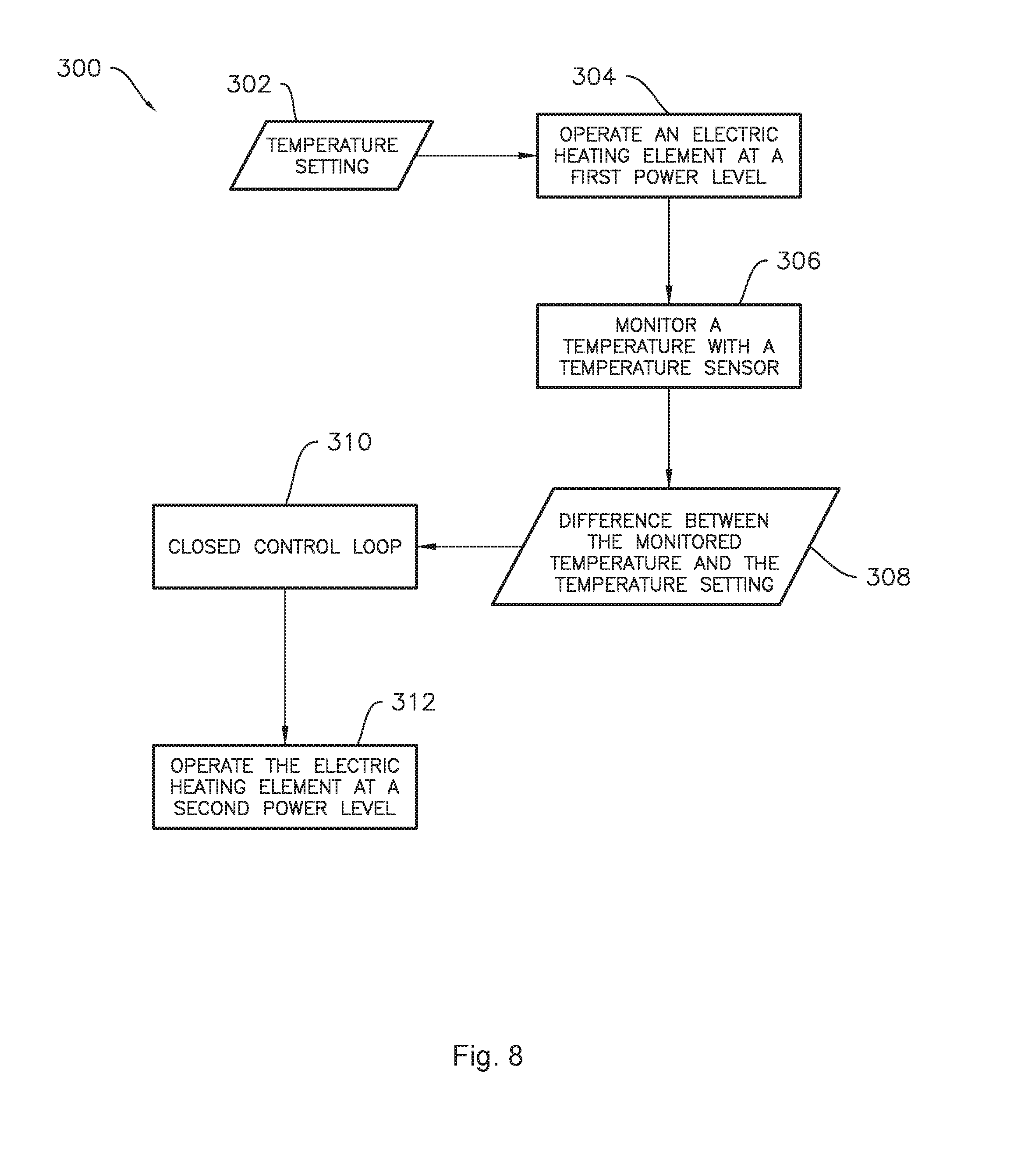
[0018] FIG. 8 provides a flowchart illustrating an exemplary operation of a cooktop appliance according to one or more embodiments of the present subject matter.
DETAILED DESCRIPTION
[0019] Reference now will be made in detail to embodiments of the invention, one or more examples of which are illustrated in the drawings. Each example is provided by way of explanation of the invention, not limitation of the invention. In fact, it will be apparent to those skilled in the art that various modifications and variations can be made in the present invention without departing from the scope or spirit of the invention. For instance, features illustrated or described as part of one embodiment can be used with another embodiment to yield a still further embodiment. Thus, it is intended that the present invention covers such modifications and variations as come within the scope of the appended claims and their equivalents. As used herein, terms of approximation, such as "generally," or "about" include values within ten percent greater or less than the stated value.
[0020] FIG. 1 provides a perspective view of a range appliance, or range 10, including a cooktop appliance 12. Range 10 is provided by way of example only and is not intended to limit the present subject matter to the arrangement shown in FIG. 1. Thus, the present subject matter may be used with other range 10 and/or cooktop appliance 12 configurations, e.g., double oven range appliances, standalone cooktop appliances, cooktop appliances without an oven, etc.
[0021] A cooking surface 14 of cooktop appliance 12 includes a plurality of heating elements 16. For the embodiment depicted, the cooktop appliance 12 includes five heating elements 16 spaced along cooking surface 14. The heating elements 16 are generally electric heating elements. In certain exemplary embodiments, cooktop appliance 12 may be a radiant cooktop appliance with resistive heating elements or coils mounted below cooking surface 14. However, in other embodiments, the cooktop appliance 12 may include any other suitable shape, configuration, and/or number of heating elements 16, for example, the cooktop appliance 12 may be an open coil cooktop with the heating elements 16 positioned at or above surface 14. Additionally, in other embodiments, the cooktop appliance 12 may include any other suitable type of heating element 16, such as an induction heating element. Each of the heating elements 16 may be the same type of heating element 16, or cooktop appliance 12 may include a combination of different types of heating elements 16.
[0022] As shown in FIG. 1, a cooking utensil 18, such as a pot, pan, or the like, may be placed on a heating element 16 to heat the cooking utensil 18 and cook or heat food items placed in cooking utensil 18. Range appliance 10 also includes a door 20 that permits access to a cooking chamber (not shown) of range appliance 10, e.g., for cooking or baking of food items therein. A control panel 22 having controls 24 permits a user to make selections for cooking of food items. Although shown on a backsplash or back panel 26 of range appliance 10, control panel 22 may be positioned in any suitable location. Controls 24 may include buttons, knobs, and the like, as well as combinations thereof. As an example, a user may manipulate one or more controls 24 to select a temperature and/or a heat or power output for each heating element 16. The selected temperature or heat output of heating element 16 affects the heat transferred to cooking utensil 18 placed on heating element 16.
[0023] As will be discussed in greater detail below, the cooktop appliance 12 includes a control system 50 (FIG. 3) for controlling one or more of the plurality of heating elements 16. Specifically, the control system 50 may include a controller 52 (FIG. 3) operably connected to the control panel 22 and controls 24. The controller 52 may be operably connected to each of the plurality of heating elements 16 for controlling a power level of each of the plurality of heating elements 16 in response to one or more user inputs received through the control panel 22 and controls 24.
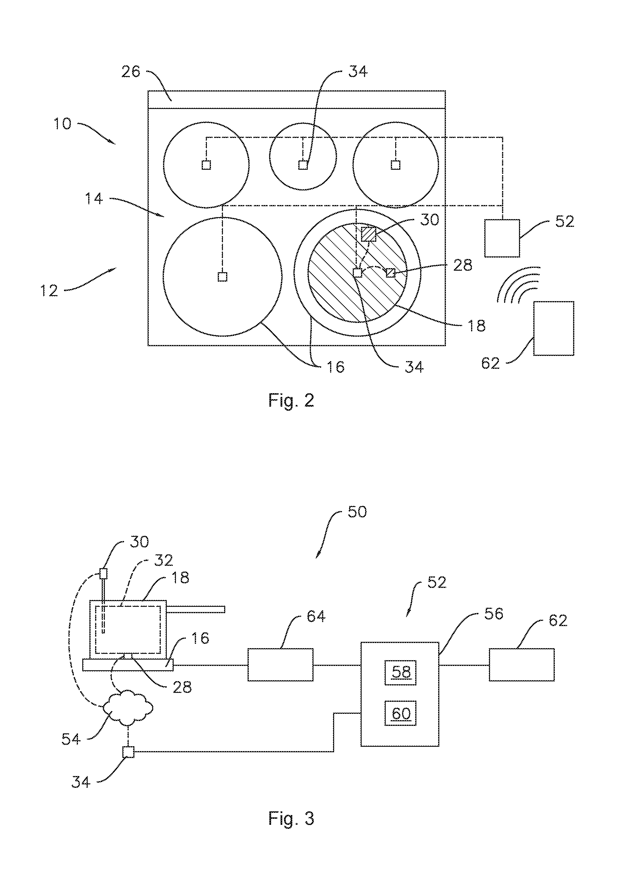
[0024] Referring now to FIG. 2, a top, schematic view of the cooktop appliance 12 of FIG. 1, or more specifically of the cooking surface 14 of the cooktop appliance 12 of FIG. 1, is provided. As stated, the cooking surface 14 of the cooktop appliance 12 for the embodiment depicted includes five heating elements 16 spaced along the cooking surface 14. A cooking utensil 18, also depicted schematically, is positioned on a first heating element 16 of the plurality of heating elements 16. For the embodiment depicted, a cookware temperature sensor 28 and a food temperature sensor 30 are also associated with the cooking utensil 18.
[0025] In some example embodiments, the cookware temperature sensor 28 may be attached to or integrated into the cooking utensil 18 and configured to sense a temperature of, e.g., a bottom surface of the cooking utensil 18 or bottom wall of the cooking utensil 18. For example, the cookware temperature sensor 28 may be embedded within the bottom wall of the cooking utensil 18 as illustrated in FIG. 3. Alternatively, however, the cookware temperature sensor 28 may be attached to or integrated within the cooking surface 14 of the cooktop appliance 12. For example, the cookware temperature sensor 28 may be integrated into one or more of the heating elements 16, as illustrated in FIG. 4. With such an exemplary embodiment, the cookware temperature sensor 28 may be configured to physically contact the bottom surface of a bottom wall of the cooking utensil 18 when the cooking utensil 18 is placed on the heating element 16 of the cooking surface 14. Alternatively, cookware temperature sensor 28 may be positioned proximate to the bottom surface or bottom wall of the cooking utensil 18 when the cooking utensil 18 is placed on the heating element 16 of the cooking surface 14.
[0026] Additionally, the food temperature sensor 30 may be positioned at any suitable location to sense a temperature of one or more food items 32 (see FIG. 3) positioned within the cooking utensil 18. For example, the food temperature sensor 30 may be a probe type temperature sensor configured to be inserted into one or more food items 32. Alternatively, however, the food temperature sensor 30 may be configured to determine a temperature of one or more food items positioned within the cooking utensil 18 in any other suitable manner.
[0027] In certain exemplary embodiments, one or both of the cookware temperature sensor 28 and the food temperature sensor 30 may utilize any suitable technology for sensing/determining a temperature of the cooking utensil 18 and/or food items 32 positioned in the cooking utensil 18. The cookware temperature sensor 28 and the food temperature sensor 30 may measure a respective temperature by contact and/or non-contact methods. For example, one or both of the cookware temperature sensor 28 and the food temperature sensor 30 may utilize one or more thermocouples, thermistors, optical temperature sensors, infrared temperature sensors, etc.
[0028] Referring again to FIG. 2, the cooktop appliance 12 additionally includes at least one receiver 34. In the illustrated example of FIG. 2, the cooktop appliance 12 includes a plurality of receivers 34, each receiver 34 associated with an individual heating element 16. Each receiver 34 is configured to receive a signal from the food temperature sensor 30 indicative of a temperature of the one or more food items 32 positioned within the cooking utensil 18 and from the cookware temperature sensor 28 indicative of a temperature of the cooking utensil 18 positioned on a respective heating element 16. In other embodiments, a single receiver 34 may be provided and the single receiver 34 may be operatively connected to one or more than one of the sensors. In at least some exemplary embodiments, one or both of the cookware temperature sensor 28 and the food temperature sensor 30 may include wireless transmitting capabilities, or alternatively may be hard-wired to the receiver 34 through a wired communications bus.
[0029] Referring now also to FIG. 3, a schematic view of a system for operating a cooktop appliance 12 in accordance with an exemplary embodiment of the present disclosure is provided. Specifically, FIG. 3 provides a schematic view of a heating element 16 of the exemplary cooktop appliance 12 of FIGS. 1 and 2 and an exemplary control system 50.
[0030] As stated, the cooktop appliance 12 includes a receiver 34 associated with one or more of the heating elements 16, for example a plurality of receivers 34 each associated with a respective heating element 16. For the embodiment depicted, each receiver 34 is positioned directly below a center portion of a respective heating element 16. Moreover, for the embodiment depicted, each receiver 34 is configured as a wireless receiver 34 configured to receive one or more wireless signals. Specifically, for the exemplary control system 50 depicted, both of the cookware temperature sensor 28 and the food temperature sensor 30 are configured as wireless sensors in wireless communication with the wireless receiver 34 via a wireless communications network 54. In certain exemplary embodiments, the wireless communications network 54 may be a wireless sensor network (such as a Bluetooth communication network), a wireless local area network (WLAN), a point-to point communication networks (such as radio frequency identification (RFID) networks, near field communications networks, etc.), a combination of two or more of the above communications networks, or any suitable wireless communications network or networks.
[0031] Referring still to FIG. 3, each receiver 34 associated with a respective heating element 16 is operably connected to a controller 52 of the control system 50. The receivers 34 may be operably connected to the controller 52 via a wired communication bus (as shown), or alternatively through a wireless communication network similar to the exemplary wireless communication network 54 discussed above. The controller 52 may generally include a computing device 56 having one or more processor(s) 58 and associated memory device(s) 60. The computing device 56 may be configured to perform a variety of computer-implemented functions to control the exemplary cooktop appliance 12. The computing device 56 can include a general purpose computer or a special purpose computer, or any other suitable computing device. It should be appreciated, that as used herein, the processor 58 may refer to a controller, a microcontroller, a microcomputer, a programmable logic controller (PLC), an application specific integrated circuit, and other programmable circuits. Additionally, the memory device(s) 60 may generally comprise memory element(s) including, but not limited to, computer readable medium (e.g., random access memory (RAM)), computer readable non-volatile medium (e.g., a flash memory), a compact disc-read only memory (CD-ROM), a magneto-optical disk (MOD), a digital versatile disc (DVD), and/or other suitable memory elements. The memory 60 can store information accessible by processor(s) 58, including instructions that can be executed by processor(s) 58. For example, the instructions can be software or any set of instructions that when executed by the processor(s) 58, cause the processor(s) 58 to perform operations. For the embodiment depicted, the instructions may include a software package configured to operate the system to, e.g., execute the exemplary methods described below.
[0032] Referring still to FIG. 3, the control system 50 additionally includes a user interface 62 operably connected to the controller 52. For the embodiment depicted, e.g., in FIG. 3, the user interface 62 is configured in wired communication with the controller 52. However, in other exemplary embodiments, e.g., as shown in FIG. 2, the user interface 62 may additionally or alternatively be wirelessly connected to the controller 52 via one or more suitable wireless communication networks (such as the exemplary wireless communication network 54 described above). In certain exemplary embodiments, user interface 62 may be configured as the control panel 22 and plurality of controls 24 on the cooktop appliance 12 (see FIG. 1). Additionally, or alternatively, the user interface 62 may be configured as an external computing device or remote user interface device, such as a smart phone, tablet, or other device capable of connecting to the controller 52 of the exemplary control system 50. For example, in some embodiments, the remote user interface may be an application or "app" executed by a remote user interface device such as a smart phone or tablet. Signals generated in controller 52 operate appliance 12 in response to user input via the user interface 62.
[0033] Further, the controller 52 is operably connected to each of the plurality of heating elements 16 for controlling a power level of each of the plurality of heating elements 16 in response to one or more user inputs through the user interface 62 (e.g., control panel 22 and controls 24). Specifically, for the embodiment depicted, the controller 52 is operably connected to a plurality of power level control devices 64, each power level control device 64 associated with a respective one of the heating elements 16. For example, wherein one or more of the heating elements 16 are configured as electric resistance heaters, the controller 52 may be operably connected to respective relays, triodes for alternating current (TRIACS), or other devices for controlling an amount of power to such electrical resistance heaters. Alternatively, in embodiments wherein one or more of the heating elements 16 are configured as induction heating elements, the controller 52 may be operably connected to respective current control devices.
[0034] In some exemplary embodiments, the power level as described herein may be a function of applied voltage and time. For example, in embodiments where the heating elements 16 are resistance heating elements, the resistance heating elements 16 may be operated over a duty cycle which includes a defined period of time, such as about thirty seconds. The total time period of the duty cycle may be allocated between an on duration and an off duration. Continuing the example, if the total duty cycle is thirty seconds long, the on duration may be twenty-seven seconds, where the off duration would then be three seconds, after which a subsequent duty cycle may be performed. Thus, the power level e.g., the average power supplied in a given duty cycle, is a function of applied voltage and time, e.g., the length of the on duration of the duty cycle. Accordingly, the average power supplied in a given duty cycle can be controlled by varying the magnitude of applied voltage and/or the proportion of the duty cycle in which the voltage is applied (e.g., the on duration). Thus, for example, operation of the cooktop appliance 12 may include a first cycle, such as a preheat cycle, wherein a first voltage is applied across the electric heating element 16 continuously throughout the first cycle. The first cycle may be followed by one or more subsequent cycles, e.g., a second cycle, a third cycle, etc. In some embodiments, the one or more subsequent cycles may include one or more duty cycles. In the one or more duty cycles, a voltage, e.g., the first voltage or a second voltage less than the first voltage, is applied across the electric heating element over a first period of time, e.g., an on duration, and the electric heating element 16 is deactivated for a second period of time, e.g., an off duration, and the first and second periods of time collectively define the duty cycle.
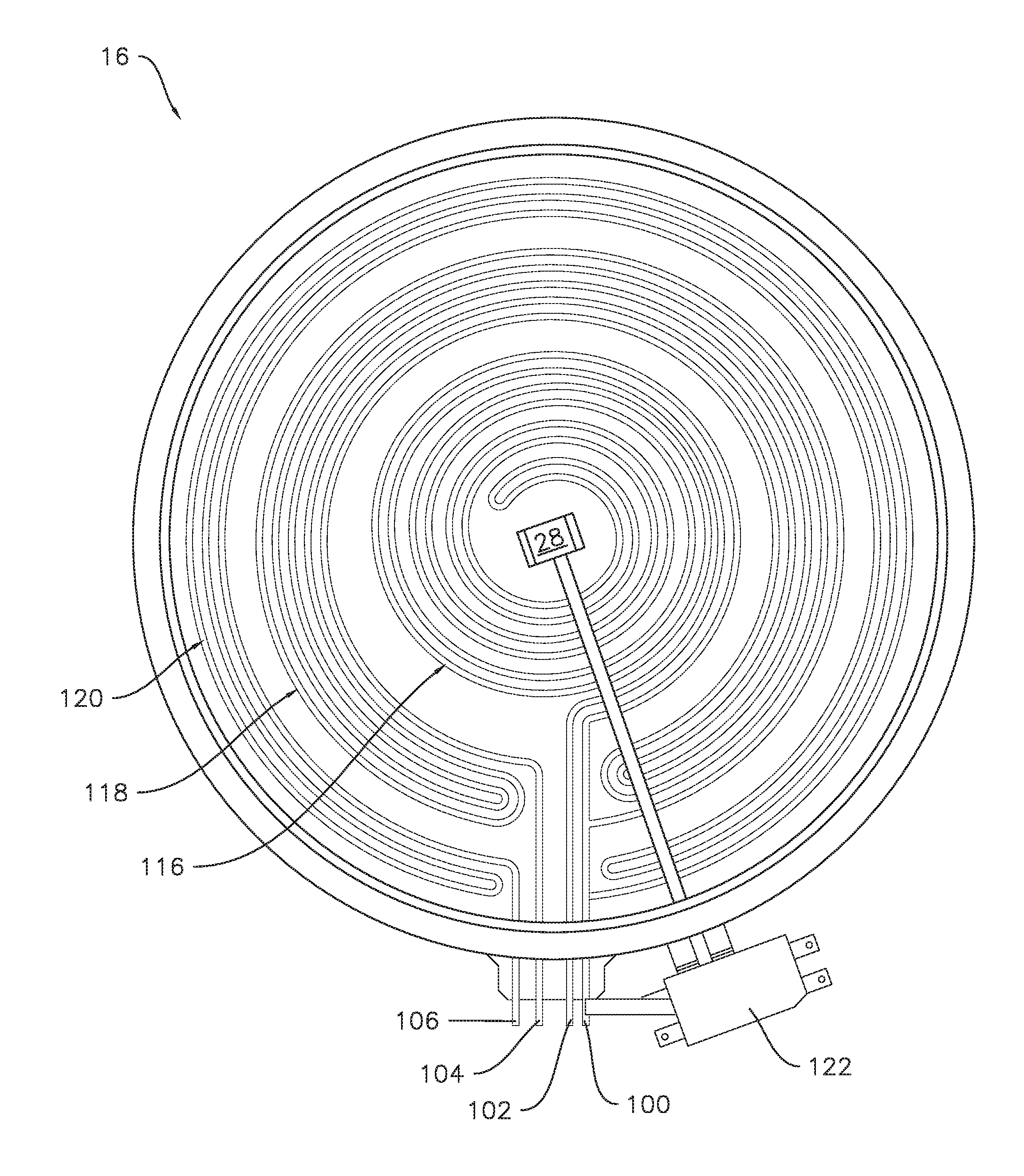
[0035] An exemplary resistance heating element 16 is illustrated in FIG. 4. In the illustrated example embodiment, the heating element 16 comprises a temperature limiter 122 and a plurality of terminals. In particular, the exemplary heating element 16 illustrated in FIG. 4 includes a first terminal 100, a second terminal 102, a third terminal 104, and a fourth terminal 106. As shown, the exemplary heating element 16 includes three rings, e.g., a first ring 116 corresponding to the second terminal 102, a second ring 118 corresponding to the third terminal 104, and a third ring 120 corresponding to the fourth terminal 106. A voltage may be applied across all or a selected one or more of the rings 116, 118, and 120 by connecting a voltage source across the first terminal 100 and one of the second terminal 102, third terminal 104, and fourth terminal 106.
[0036] In some exemplary embodiments, the power level control device 64 may include one or more relays configured to connect selected terminals of the heating element 16 to electrical conduits configured to operate at a desired voltage with respect to ground. One such example is illustrated in FIG. 5, where the power level control is provided by a first relay 63 and a second relay 65. That is, in the illustrated exemplary embodiment, the power level, e.g. the average power supplied during a duty cycle, may be controlled at least by operating the heating element at a variable voltage using the relays 63 and 65, as described in more detail herein. As illustrated, the first relay 63 is coupled to the first terminal 100 of the electric heating element 16 and configured to selectively connect the first terminal 100 of the electric heating element 16 to one of a neutral electrical conduit 108 and a first electrical conduit 110 configured to operate at a third voltage with respect to ground. Thus, first electrical conduit 110 may be coupled or connected to a first voltage source operating at the first voltage with respect to ground. Also as shown in FIG. 5, the second relay 65 is coupled to the second terminal 102 of the electric heating element 16. In the particular exemplary embodiment illustrated by FIG. 5, the second relay 65 is also connected to the third terminal 104 and fourth terminal 106. In other embodiments, the heating element 16 may include only the first and second terminals 100 and 102. In still further embodiments where the heating element 16 comprises a plurality of rings, e.g., the first, second, and third rings 116, 118, and 120 as in the illustrated exemplary embodiment, and a corresponding number of terminals, each terminal may be connected to a dedicated relay with each dedicated relay only connected to a single terminal and no other terminals. For example, a third relay may be provided connected to the third terminal 104 and a fourth relay may be provided connected to the fourth terminal 106, etc. The second relay is configured to selectively connect the second terminal 102 of the electric heating element 16 to one of a second electrical conduit 112 configured to operate at a fourth voltage with respect to ground, and an open circuit 114. The second electrical conduit 112 may be coupled or connected to a second voltage source operating at the second voltage with respect to ground. Neutral electrical conduit 108 is configured for operating at neutral. Thus, neutral electrical conduit 108 may be grounded. The first, second and neutral electrical conduits 108, 110, and 112 may be any suitable electrical conduits, such as wires, cables, etc. In the illustrated example embodiment, the second relay is also configured to selectively connect one or both of the third terminal 104 and fourth terminal 106 to one of the second electrical conduit 112 and the open circuit 114.
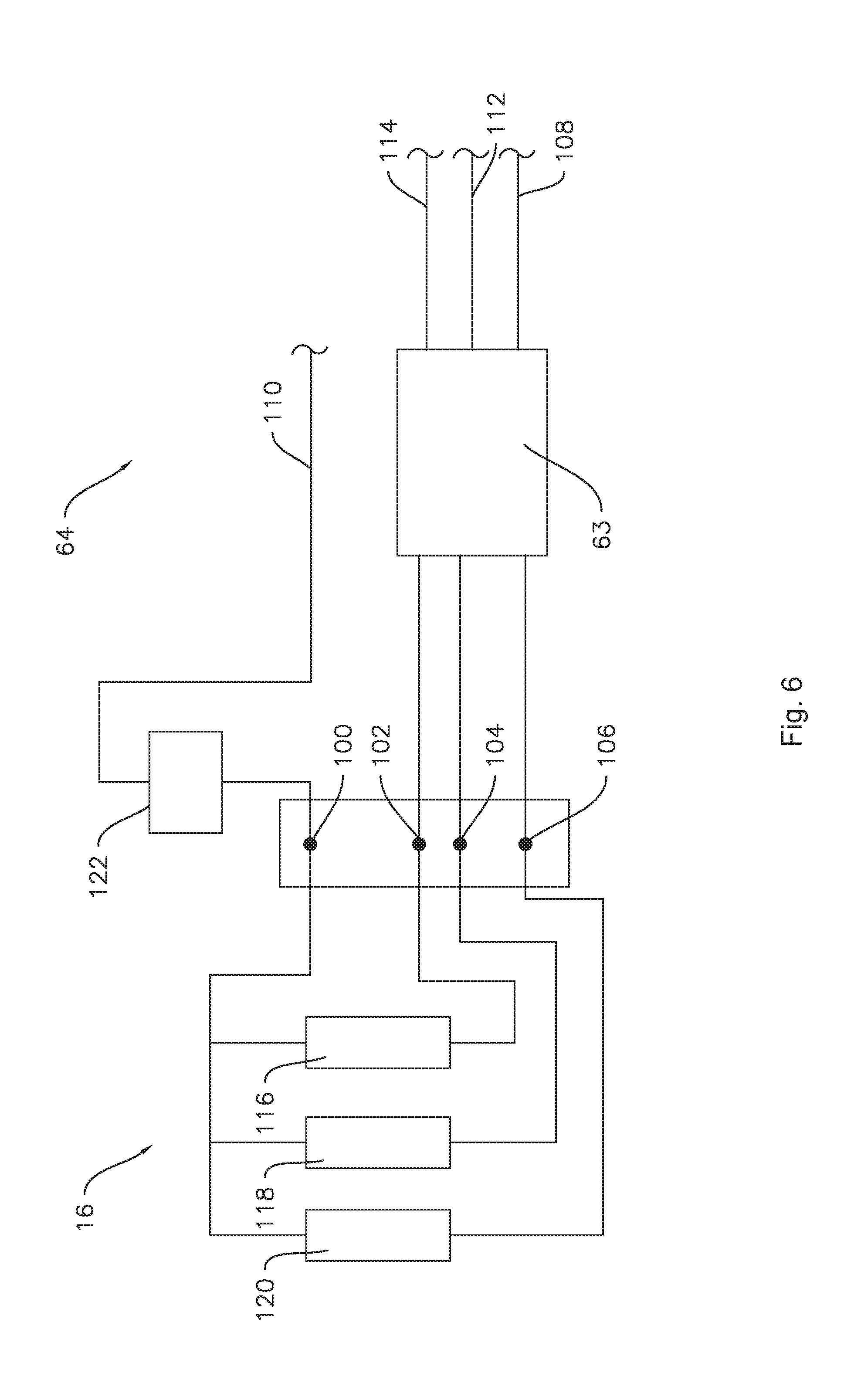
[0037] As another example, only the first relay 63 may be provided in some embodiments. For example, as illustrated in FIG. 6, the relay 63 may be a three-way relay that switches between off, the first voltage and the second voltage. In such embodiments, the relay 63 may be configured to connect a selected one of the neutral electrical conduit 108, the second electrical conduit 112, and the open circuit 114 to one or more of the second terminal 102, the third terminal 104, and the fourth terminal 106. In such embodiments, the first terminal 100 may be connected to the first electrical conduit 110 without an intervening switch or relay. The first voltage and the second voltage may have opposite polarities. In addition, a magnitude of the first voltage with respect to ground may be about equal to a magnitude of the second voltage with respect to ground. As used herein, the term "about" corresponds to within ten volts of a stated voltage when used in the context of voltage. As an example, the magnitude of the first and second voltages may be about one hundred and twenty volts with respect to ground. Thus, e.g., first electrical conduit 110 may be coupled to one phase of a two hundred and forty volt household electrical supply, and second electrical conduit 112 may be coupled to the second phase of the two hundred and forty volt household electrical supply. Neutral electrical conduit 108 may be grounded.
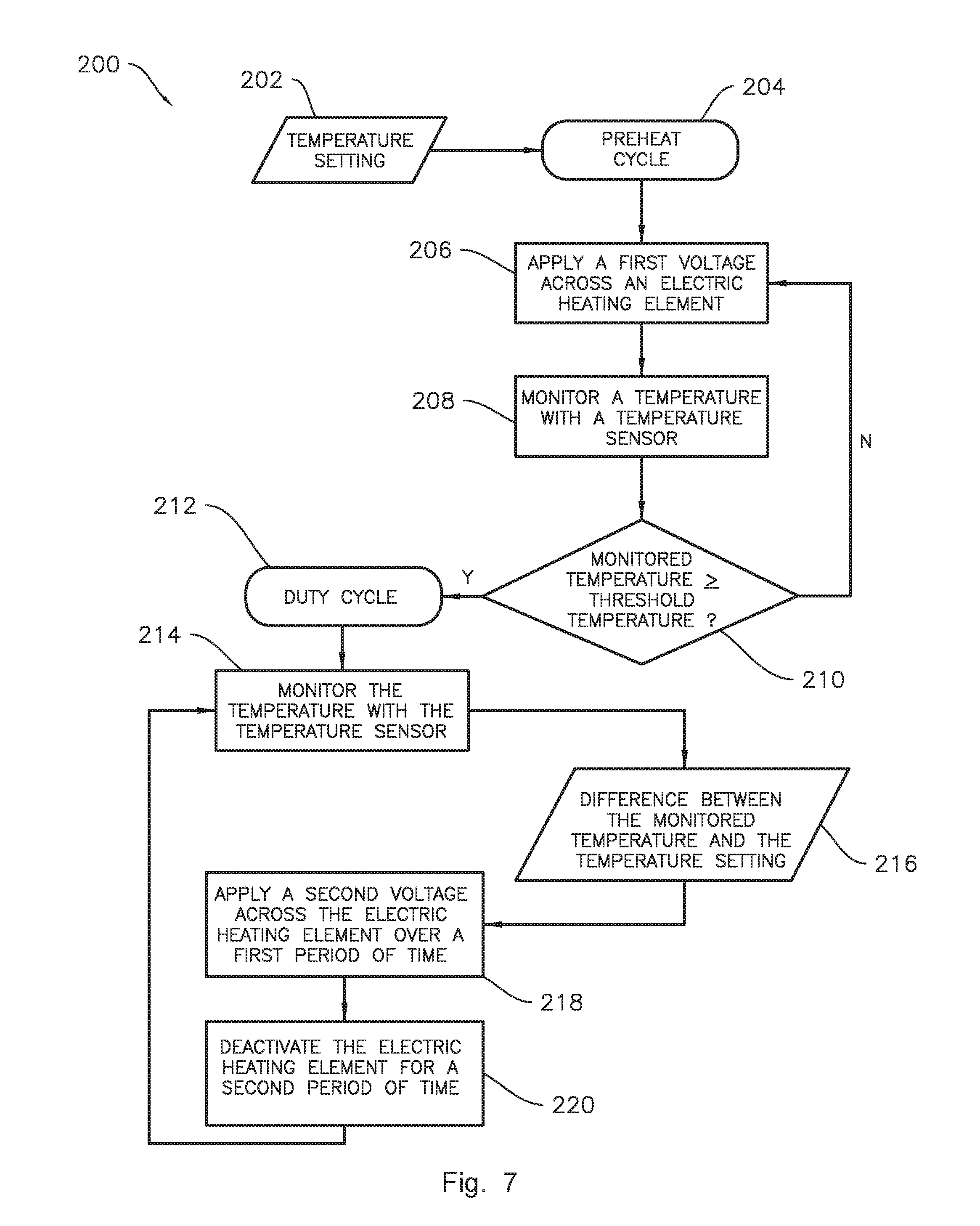
[0038] FIG. 7 illustrates an exemplary method 200 of operating a cooktop appliance, such as the exemplary cooktop 12. In some embodiments, the controller 52 may be configured to perform some or all of the steps of method 200. The method 200 may include a step 202 of generating or receiving a temperature setting. For example, the cooktop appliance 12 and/or a controller 52 thereof may be configured to generate a temperature setting, e.g., the temperature setting may be generated by the controller 52 in response to a user input received via the user interface 62 (FIG. 3). The controller 52 may be further configured for initiating the first cycle, e.g., preheat cycle, e.g., at step 204 of the exemplary method 200. The preheat cycle may include operating a heating element 16 at a predetermined power level corresponding to the temperature setting and monitoring a temperature with temperature sensor 30 until the monitored temperature reaches a threshold temperature. In some embodiments, the threshold temperature may be less than the temperature setting. For example, the threshold temperature may be a predetermined percentage of the temperature setting, such as about ninety-five percent (95%) or less, such as about ninety percent (90%) or less, such as about eighty percent (80%) or less, such as about seventy-five percent (75%) or less. Providing the threshold temperature less than the temperature setting accounts for thermal lag, e.g., a decrease in the rate of temperature increase will lag behind a decrease in the supplied power level, such that the threshold temperature less than the temperature setting may reduce or avoid overshooting the temperature setting at the end of the preheat cycle.
[0039] For example, operating the heating element 16 at the predetermined power level in response to the temperature setting may include applying the first voltage across the electric heating element 16, as illustrated at step 206 of method 200. In some embodiments, applying the first voltage across the electric heating element 16 may include connecting the first terminal 100 of the electric heating element 16 to the first electrical conduit 110 and connecting the second terminal 102 of the electric heating element 16 to the second electrical conduit 112.
[0040] As mentioned above, the method 200 may include monitoring a temperature with a temperature sensor, e.g., at step 208. The temperature may be monitored with one or both of the cookware temperature sensor 28 and the food temperature sensor 30, e.g., temperature values may be continuously measured by the temperature sensor(s) 28 and/or 30 over time during the operation of the cooktop appliance 12. Thus, it should be understood that "monitored," "monitoring," or other cognates thereof as used herein include continuous or repeated measuring or sampling of data, e.g., temperature, over a period of time. Further, in various embodiments, the temperature sensor used in the monitoring steps, e.g., step 208, may be one or both of the cookware temperature sensor 28 and the food temperature sensor 30, and the monitored temperature may be one or both of a temperature of cooking utensil 18 and a temperature of food item 32.
[0041] The method 200 may also include determining, at step 210, whether the monitored temperature is greater than or equal to the threshold temperature. When the monitored temperature is less than the threshold temperature, e.g., when the determination at step 210 is negative, the preheat cycle continues by returning to method step 206 and continuing to operate at the first power level, e.g., applying the first voltage. When the monitored temperature is greater than or equal to the threshold temperature, the method 200 may initiate a second cycle, e.g., a duty cycle at step 212.
[0042] For example, the controller 52 may perform step 212, e.g., the controller 52 may be configured to initiate a duty cycle of the cooktop appliance 12 when the monitored temperature reaches the threshold temperature. Performing the duty cycle may also include monitoring the temperature with the temperature sensor at step 214. In various embodiments, as generally shown in FIG. 7, the duty cycle may include adjusting a power level of the heating element 16 based at least in part on the monitored temperature. As noted above and discussed in more detail below, the power level may be a function of the voltage applied and the length of the on duration in the duty cycle. As such, adjusting one or both of the applied voltage and the length of the on duration and off duration may adjust the power level.
[0043] As noted above, the duty cycle encompasses a time period including both an on duration and an off duration. The relative length of time in the on duration and the off duration affects the power level, e.g., the average power of the duty cycle. Moreover, one or both of the temperature sensors 28 and 30 may continuously supply a temperature reading to the controller 52 during the duty cycle such that the duty cycle may include monitoring the temperature with the temperature sensor(s) 28 and/or 30, e.g., at step 214. At various points in time throughout the duty cycle, the monitored temperature may vary above and below the temperature setting. The controller 52 may be configured for calculating a difference between the monitored temperature and the temperature setting, e.g., at step 216. The duty cycle may include operating the electric heating element 16 over a first period of time, e.g., the on duration. The adjustment of the power level may be based at least in part on the monitored temperature, e.g., may be based at least in part on the calculated difference between the monitored temperature and the temperature setting. For example, the difference between the monitored temperature and the temperature setting may be input into a control loop, which is generally a closed control loop, such as a proportional-integral-derivative (PID) control loop or a proportional-integral (PI) control loop, and the controller 52 may be configured for adjusting the power level of the heating element 16 based on the output of the control loop, e.g., by determining a duration of the first period of time based on the calculated difference between the monitored temperature and the temperature setting.
[0044] The on duration may be embodied by step 218 of applying a second voltage across the heating element 16 over a first period of time. Note that the heating element 16 is active and operating during the on duration, e.g., the second voltage applied at step 218 is a non-zero voltage. In various embodiments, a magnitude of the second voltage may be less than a magnitude of the first voltage. For example, applying the second voltage across the electric heating element 16 may include connecting the first terminal 100 of the electric heating element 16 to the neutral conduit 108 and connecting the second terminal 102 of the electric heating element 16 to the second electrical conduit 112. Accordingly, in some such embodiments, the first voltage may be two hundred forty volts with respect to ground and the second voltage may be one hundred twenty volts with respect to ground.
[0045] The duty cycle may also include an off duration, e.g., deactivating the heating element 16 for a second period of time, as shown at method step 220 in FIG. 7. In some embodiments, deactivating the electric heating element 16 may include connecting the second terminal 102 of the electric heating element 16 to the open circuit 114. One of ordinary skill will recognize that the heating element 16 is not operating during the off duration. The controller 52 may be configured for deactivating the heating element 16 for the second period of time based at least in part on the monitored temperature, e.g., based at least in part on the calculated difference between the monitored temperature and the temperature setting. For example, when the monitored temperature is greater than the temperature setting, the controller 52 may deactivate the heating element 16 for the second period of time, e.g., a length of an off duration, based on the magnitude of the difference between the monitored temperature and the temperature setting. Following the off duration, the controller 52 may initiate a subsequent duty cycle, e.g., as shown in FIG. 6, the method may return to step 214 after step 220.
[0046] As discussed above, the duty cycle includes the on duration and the off duration, such that adjusting one of the on duration and the off duration also necessarily adjusts the other of the on duration and the off duration by the same amount. For example, as noted above, the duty cycle may comprise thirty seconds, the on duration may comprise twenty-seven seconds, and the off duration may comprise three seconds. In such embodiments, if the difference between the monitored temperature and the temperature setting indicates the power level should be decreased, the on duration may be adjusted to twenty-four seconds, whereby the off duration would then be six seconds. Thus, in these embodiments, each duty cycle during operation of the cooktop appliance 12 includes monitoring a temperature (e.g., step 214), calculating a difference between the monitored temperature and a temperature setting (e.g., step 216), and determining the on and off durations of the present duty cycle (e.g. the first and second time periods in steps 218 and 220) based on the calculated difference.
[0047] FIG. 8 provides an illustrative flow chart of an example method 300 of operating a cooktop appliance. It should be understood that the control system 50 and/or controller 52 described hereinabove may be configured for performing some or all of the steps of the exemplary method 300. As shown in FIG. 8, the method 300 may include generating a temperature setting at step 302, e.g., in response to a user input received via a user interface. The method 300 may also include a step 304 of operating the heating element 16 at a first power level. As discussed above, the first power level may be an average power of a first duty cycle, which may be determined by a voltage applied during an on duration of the first duty cycle and a time length of the on duration. The method 300 may also include a step 306 of monitoring a temperature, e.g., of cooking utensil 18 and/or food item 32, with a temperature sensor, e.g., one or both of the cookware temperature sensor 28 and the food temperature sensor 30.
[0048] In some example embodiments, the method 300 may include and/or the controller 52 may be configured for inputting the monitored temperature into a closed control loop, e.g., a PID control loop or a PI control loop, at step 310. In some embodiments, the method 300 may also include calculating a difference between the monitored temperature and the temperature setting, e.g., at step 308, and inputting the calculated difference as well as or instead of the monitored temperature into the control loop at step 310.
[0049] The method 300 may further include and/or the controller 52 may further be configured for operating the heating element 16 at a second power level based at least in part on an output of the control loop. For example, the second power level may be an average power of a second duty cycle subsequent to the first duty cycle described above. Accordingly, operating the electric heating element 16 at the first power level may comprise applying a first voltage across the electric heating element for a first duration, e.g., an on duration of the first duty cycle, and operating the electric heating element 16 at the second power level may comprise applying a second voltage across the electric heating element 16 for a second duration, e.g., an on duration of the second duty cycle. In some embodiments, the second voltage may be different from, e.g., less than, the first voltage. In various embodiments, the first duration and the second duration may be the same, or the first duration and the second duration may differ.
[0050] In some embodiments, the first power level may be a preheat power level. For example, the controller 52 may be configured for operating the electric heating element at the first power level until the monitored temperature reaches a threshold temperature, the threshold temperature less than the temperature setting, and inputting the monitored temperature into the closed control loop after the monitored temperature reaches the threshold temperature.
[0051] This written description uses examples to disclose the invention, including the best mode, and also to enable any person skilled in the art to practice the invention, including making and using any devices or systems and performing any incorporated methods. The patentable scope of the invention is defined by the claims, and may include other examples that occur to those skilled in the art. Such other examples are intended to be within the scope of the claims if they include structural elements that do not differ from the literal language of the claims, or if they include equivalent structural elements with insubstantial differences from the literal languages of the claims.
* * * * *
D00000
D00001
D00002
D00003
D00004
D00005
D00006
D00007
XML
uspto.report is an independent third-party trademark research tool that is not affiliated, endorsed, or sponsored by the United States Patent and Trademark Office (USPTO) or any other governmental organization. The information provided by uspto.report is based on publicly available data at the time of writing and is intended for informational purposes only.
While we strive to provide accurate and up-to-date information, we do not guarantee the accuracy, completeness, reliability, or suitability of the information displayed on this site. The use of this site is at your own risk. Any reliance you place on such information is therefore strictly at your own risk.
All official trademark data, including owner information, should be verified by visiting the official USPTO website at www.uspto.gov. This site is not intended to replace professional legal advice and should not be used as a substitute for consulting with a legal professional who is knowledgeable about trademark law.