Wellbore Pumps In Series, Including Device To Separate Gas From Produced Reservoir Fluids
Hansen; Henning
U.S. patent application number 16/440902 was filed with the patent office on 2019-09-26 for wellbore pumps in series, including device to separate gas from produced reservoir fluids. The applicant listed for this patent is Hansen Downhole Pump Solutions AS. Invention is credited to Henning Hansen.
| Application Number | 20190292889 16/440902 |
| Document ID | / |
| Family ID | 60702899 |
| Filed Date | 2019-09-26 |


| United States Patent Application | 20190292889 |
| Kind Code | A1 |
| Hansen; Henning | September 26, 2019 |
WELLBORE PUMPS IN SERIES, INCLUDING DEVICE TO SEPARATE GAS FROM PRODUCED RESERVOIR FLUIDS
Abstract
A pump system for a wellbore includes a production tubing nested within a wellbore. At least two pumps are disposed in the production tubing and are axially spaced apart from each other. One of the pumps is removable from the production tubing while the production tubing remains in place. A fluid intake conduit is disposed outside the production. The fluid intake conduit is in fluid communication with an interior of the production tubing below a lower one of the pumps and at a position of an intake of an upper one of the pumps. At least one fluid discharge conduit is disposed outside the tubing and inside the wellbore. The at least one fluid discharge conduit is in fluid communication with the interior of the production tubing proximate a discharge of the lower one of the pumps and above the upper one of the pumps.
| Inventors: | Hansen; Henning; (Dolores, ES) | ||||||||||
| Applicant: |
|
||||||||||
|---|---|---|---|---|---|---|---|---|---|---|---|
| Family ID: | 60702899 | ||||||||||
| Appl. No.: | 16/440902 | ||||||||||
| Filed: | June 13, 2019 |
Related U.S. Patent Documents
| Application Number | Filing Date | Patent Number | ||
|---|---|---|---|---|
| PCT/IB2017/057503 | Nov 29, 2017 | |||
| 16440902 | ||||
| 62440060 | Dec 29, 2016 | |||
| Current U.S. Class: | 1/1 |
| Current CPC Class: | F04D 13/10 20130101; E21B 43/128 20130101 |
| International Class: | E21B 43/12 20060101 E21B043/12; F04D 13/10 20060101 F04D013/10 |
Claims
1. A pump system for a wellbore, comprising: a production tubing disposed in a wellbore; at least two pumps disposed in the production tubing and axially spaced apart from each other, at least one of the at least two pumps removable from the production tubing while the production tubing remains in place in the wellbore; and at least one fluid intake conduit disposed outside the production tubing and inside the wellbore, the at least one fluid intake conduit in fluid communication with and providing a fluid transport path between an interior of the production tubing below a lower one of the at least two pumps and at a position of an intake of an upper one of the at least two pumps; and at least one fluid discharge conduit disposed outside the tubing and inside the wellbore, the at least one fluid discharge conduit in fluid communication with and providing a fluid transport path between the interior of the production tubing at a discharge of the lower one of the at least two pumps and either at an intake of or above the upper one of the at least two pumps.
2. The system of claim 1 wherein at least the upper one of the at least two pumps is seated in a wet mateable electrical/mechanical connector disposed in the production tubing.
3. The system of claim 1 wherein both the upper one and the lower one of the at least two pumps is seated in a respective wet mateable electrical/mechanical connector disposed in the production tubing.
4. The system of claim 1 further comprising a gas separator disposed in the production tubing below the lower one of the at least two pumps, the gas separator having at least one gas discharge conduit disposed outside the tubing and inside the wellbore, the gas discharge conduits in fluid communication with the interior of the production tubing above the upper one of the at least two pumps.
5. The system of claim 4 further comprising a booster disposed above the upper one of the at least two pumps having an intake in fluid communication with the at least one gas discharge conduit, an outlet of the booster in fluid communication with an interior of the production tubing.
6. The system of claim 3 wherein the gas separator comprises an inner tube nested within an outer tube having fluid entry ports, the inner tube having fluid entry ports at an axial position below the fluid entry ports in the outer tube, a seal disposed between the inner tube and the outer tube disposed at a longitudinal position above the fluid entry ports in the outer tube, the seal having at least one gas discharge tube passing therethrough.
7. The system of claim 1 wherein at least the upper one of the at least two pumps is sealingly engaged to the interior of the production tubing so as to substantially prevent movement of fluid between an interior of the production tubing and an exterior of the at least the upper one of the at least two pumps.
8. The system of claim 1 wherein the at least two pumps comprise electrically submersible pumps.
9. The system of claim 1 further comprising an annular seal element disposed between the production tubing and a casing disposed in the wellbore, the annular seal element disposed at a position below the lower one of the at least two pumps.
10. The system of claim 1 wherein the lower one of the at least two pumps is coupled to the production tubing so as to require removal of the production tubing to remove the lower one of the at least two pumps from the wellbore.
11. The system of claim 1 further comprising a plurality of fluid flow conduits each being in fluid communication with an interior of the production tubing at longitudinal positions corresponding to fluid communication positions of the at least one fluid intake conduit.
12. The system of claim 1 further comprising a plurality of fluid flow conduits each being in fluid communication with an interior of the production tubing at longitudinal positions corresponding to fluid communication positions of the at least one fluid discharge conduit.
13. The system of claim 1 wherein each of the at least two pumps has a fluid pumping rate enabling lift of a full flow rate of fluid from the wellbore to the surface, whereby failure of one of the at least two pumps enables substitution of the other of the at least two pumps to maintain full fluid flow from the wellbore to the surface.
14. The system of claim 1 wherein the at least two pumps have an outer diameter and/or a length such that the at least two pumps are able to move through a point of maximum dog leg severity in the wellbore.
15. The system of claim 1 further comprising at least a third pump disposed in the production tubing intermediate the upper one of the at least two pumps and the lower one of the at least two pumps, the at least a third pump having at least one respective fluid intake conduit disposed outside the production tubing and inside the wellbore, the at least one respective fluid intake conduit in communication with the interior of the production tubing below the lower one of the at least two pumps and at a position of an intake of the at least a third pump, the at least a third pump having at least one respective fluid discharge conduit disposed outside the tubing and inside the wellbore, the at least one fluid discharge conduit in fluid communication with the interior of the production tubing proximate a discharge of the at least a third pump and either proximate the intake of or above the upper one of the at least two pumps.
16. The system of claim 15 wherein the at least a third pump is seated in a respective wet mateable electrical/mechanical connector disposed in the production tubing.
17. The system of claim 16 wherein the at least a third pump is removable from the production tubing without removing the production tubing from the wellbore.
18. The system of claim 15 wherein any combination of two of the upper one of the at least two pumps and the at least a third pump has a fluid pumping rate enabling lift of a full flow rate of fluid from the wellbore to the surface, whereby failure of any one of the at least two pumps and the at least a third pump enables substitution of the other of the at least two pumps to maintain full fluid flow from the wellbore to the surface.
19. A method for pumping fluid from a wellbore, comprising: operating at least one of at least two pumps disposed in a production tubing disposed in the wellbore, at least one of the at least two pumps removable from the production tubing while the production tubing remains in place in the wellbore, at least one fluid intake conduit disposed outside the production tubing and inside the wellbore, the at least one fluid intake conduit in fluid communication with and providing a fluid transport path between an interior of the production tubing below a lower one of the at least two pumps and at a position of an intake of an upper one of the at least two pumps, at least one fluid discharge conduit disposed outside the tubing and inside the wellbore, the at least one fluid discharge conduit in fluid communication with and providing a fluid transport path between the interior of the production tubing at a discharge of the lower one of the at least two pumps and either at an intake of or above the upper one of the at least two pumps.
20. The method of claim 19 wherein each of the at least two pumps has a fluid pumping rate enabling lift of a full flow rate of fluid from the wellbore to the surface, whereby failure of one of the at least two pumps enables substitution of the other of the at least two pumps to maintain full fluid flow from the wellbore to the surface.
21. The method of claim 19 further comprising operating at least a third pump disposed in the production tubing intermediate the upper one of the at least two pumps and the lower one of the at least two pumps, the at least a third pump having at least one respective fluid intake conduit disposed outside the production tubing and inside the open wellbore, the at least one respective fluid intake conduit in communication with the interior of the production tubing below the lower one of the at least two pumps and at a position of an intake of the at least a third pump, the at least a third pump having at least one respective fluid discharge conduit disposed outside the tubing and inside the wellbore, the at least one fluid discharge conduit in fluid communication with the interior of the production tubing proximate a discharge of the at least a third pump and either proximate the intake of or above the upper one of the at least two pumps.
22. The method of claim 21 wherein any combination of two of the upper one of the at least two pumps and the at least a third pump has a fluid pumping rate enabling lift of a full flow rate of fluid from the wellbore to the surface, whereby failure of any one of the at least two pumps and the at least a third pump enables substitution of the other of the at least two pumps to maintain full fluid flow from the wellbore to the surface.
Description
CROSS REFERENCE TO RELATED APPLICATIONS
[0001] Continuation of International Application No. PCT/IB2017/057503 filed on Nov. 29, 2017. Priority is claimed from U.S. Provisional Application No. 62/440,060 filed on Dec. 29, 2016. Both the foregoing applications are incorporated herein by reference in their entirety.
STATEMENT REGARDING FEDERALLY SPONSORED RESEARCH OR DEVELOPMENT
[0002] Not Applicable
NAMES OF THE PARTIES TO A JOINT RESEARCH AGREEMENT
[0003] Not Applicable.
BACKGROUND
[0004] This disclosure relates to the field of producing fluids from underground wellbores, where the fluids need artificial assistance to be transported to the surface.
[0005] Wellbores used for the production of fluids disposed in underground formations (for example from a hydrocarbon reservoir) to the surface often must be equipped with artificial lift devices such as downhole pumps to assist pushing fluids to the outlet of the wellbore proximate the surface. A common pump type is electrically driven, and is known as an electrical submersible pump (ESP). To obtain various fluid lift rates to the surface, the length and dimension of the pump determines the fluid flow rate to surface that may be obtained. ESP fluid lift flow rates typically are related to the outer diameter and length of the ESP. Smaller diameter and smaller length corresponds to lower possible flow rates; larger outer diameter and longer pumps may have higher possible flow rates.
[0006] Often wellbores include a conduit called a "casing" that has a less than optimum internal diameter for an artificial lift system to be installed, which frequently means that a pump (e.g., an ESP) of smaller outer dimension than may be desirable must be used, and correspondingly results in insufficient fluid lift rates to the surface. Also, wellbores are often deviated (inclined from vertical), which results in a length restriction for the pump(s); pumps generally cannot be exposed to large bending as would be required to install such pumps in a wellbore that has high change in deviation per unit length ("dog leg severity"). As an example, the productive reservoirs in the Barents Sea located north of Norway are at very shallow depths below the seafloor. Highly inclined and/or horizontal wells are often required to make producing hydrocarbons from such reservoirs economically feasible. The dog leg severity of such wells may create challenges in deploying pumps deep enough in such wells to deliver optimum flow and reservoir drainage. It should also be noted that such reservoirs will often produce fluids very close to their bubble point, further creating a need for having pumps as deep into the wellbores as possible.
[0007] Another aspect of shallow reservoirs such as may be found in the Barents Sea is that it is remote from shore, and replacing pumps that are permanently mounted onto the production tubing will require lengthy and costly mobilization of a marine drilling unit. Such conditions result in lost production while waiting for the marine drilling unit to be mobilized to the well location and made ready for the well intervention.
[0008] If pumps in subsea wells can be replaced by light intervention, as for example by wireline or similar, a less costly vessel can be used. Such vessels will most likely also have much less mobilization time than marine drilling units, which may substantially reduce lost production in case of pump failures.
[0009] Hence, there is a need for a solution to the difficulties of installing pumps in highly inclined wellbores, and in particular such wellbores located offshore.
[0010] ESPs may suffer from lack of reliability, and therefore it is an advantage to install several pumps as redundancy in a wellbore, so that production is not completely stopped in case of failure of one pump. An alternative, as described in U.S. Pat. No. 9,166,352 issued to Hansen, is to equip a pump with an electrical wet connect system, so that a pump can be retrieved and installed without having to retrieve the entire well completion system.
[0011] There are technologies known in the art where power to operate individual wellbore pumps can be engaged and disengaged downhole in the wellbore, as for example an hydraulically activated switch provided by RMS Pumptools, North Meadows Oldmeldrum Aberdeenshire AB51 0GQ, United Kingdom and described in U.S. Pat. No. 8,353,352 issued to Leitch. It is also possible to implement a downhole electronic addressing system, which could be used to engage and disengage electrical power to individual or several wellbore pumps. Operation of a downhole addressing system may be performed using an ESP power cable, or by using a separate cable that may also be used for downhole sensors and the like. Such a switching system may be incorporated into an ESP coupler as described in U.S. Pat. No. 9,166,352 issued to Hansen. Also a downhole switch is described in U.S. Patent Application Publication No. 2015/003717, entitled, "Electric submersible pump having a plurality of motors."
SUMMARY
[0012] In one aspect, the disclosure relates to a pump system for a wellbore. A pump system according to this aspect of the disclosure includes a production tubing nested within a casing in a wellbore or disposed within an open wellbore. At least two pumps are disposed in the production tubing and axially spaced apart from each other. At least one of the at least two pumps is removable from the production tubing while the production tubing remains in place in the wellbore. At least one fluid intake conduit is disposed outside the production tubing and inside the wellbore. The at least one fluid intake conduit is in fluid communication with an interior of the production tubing below a lower one of the at least two pumps and at a position of an intake of an upper one of the at least two pumps. At least one fluid discharge conduit is disposed outside the tubing and inside the wellbore. The at least one fluid discharge conduit in fluid communication with the interior of the production tubing proximate a discharge of the lower one of the at least two pumps and above the upper one of the at least two pumps.
[0013] A method for pumping fluid from a wellbore according to another aspect of the disclosure includes operating at least one of at least two pumps disposed in a production tubing disposed in the wellbore. At least one of the at least two pumps is removable from the production tubing while the production tubing remains in place in the wellbore, at least one fluid intake conduit disposed outside the production tubing and inside the wellbore, the at least one fluid intake conduit in communication with an interior of the production tubing below a lower one of the at least two pumps and at a position of an intake of an upper one of the at least two pumps, at least one fluid discharge conduit disposed outside the tubing and inside the wellbore, the at least one fluid discharge conduit in fluid communication with the interior of the production tubing proximate a discharge of the lower one of the at least two pumps and either proximate an intake of or above the upper one of the at least two pumps.
[0014] Other aspects and possible advantages of the present disclosure will be apparent from the description and claims that follow.
BRIEF DESCRIPTION OF THE DRAWINGS
[0015] FIG. 1 illustrates a wellbore consisting of a casing with a production tubing inside, where the production tubing incorporates several pumps.
[0016] FIGS. 2A, 2B and 2C illustrate a method of installing two ESPs in tandem, where fluid production from a reservoir enters the ESPs intakes from the casing side.
[0017] FIG. 3 illustrates a production tubing with several retrievable pumps placed within the tubing at various depths.
[0018] FIG. 4 illustrates a production tubing with several non-retrievable pumps placed within the tubing at various depths.
[0019] FIG. 5 illustrates that a combination of a permanently and one or more retrievable pumps are also possible, combining what is illustrated in FIG. 3 and FIG. 4.
[0020] FIG. 6 illustrates a cross section of the wellbore with the pump (including possible electrical coupler/connection), the electrical cable and several fluid transport conduits.
[0021] FIGS. 7A and 7B illustrate the difference between using a pump with a smaller outer diameter and/or shorter length to be able to be deployed further into high dog leg severity wellbores.
[0022] FIG. 8 illustrates a cross sectional example of a casing string where an ESP, an electrical wet connect, ESP cable and bypass tubing strings are shown.
[0023] FIG. 9 illustrates how an ESP assembly may be configured, including the electric wet connect system.
[0024] FIG. 10 illustrates how a gas separating device may be incorporated below the fluid distribution to the above mounted pumps.
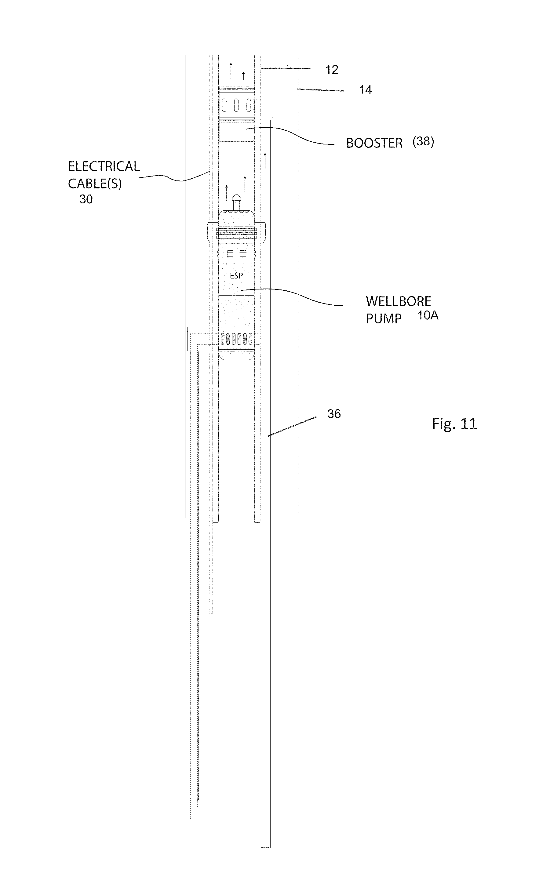
[0025] FIG. 11 illustrates a booster system receiving gas from one or several gas feeding conduit(s), and then discharging the gas into the produced fluids from one or several wellbore pumps.
[0026] FIG. 12 illustrates a gas separation system located below the pump system, where the separation system is sealing externally against the production casing.
DETAILED DESCRIPTION
[0027] The present disclosure describes structures wherein a plurality of wellbore fluid pumps can be installed in a wellbore as individual units, where each pump below an uppermost pump transfers fluids to a location above the uppermost pump, or to an area below the uppermost pump, if the uppermost pump is capable of pumping the combined volume delivered from the pumps below. Bypass (flow) conduits may be provided for transporting reservoir fluids from below the lowermost pump to one or more pumps mounted above the lowermost pump, as well as transporting fluids from the various pumps to a location below and/or above the uppermost pump. One or several fluid transport tubes may be disposed between each required pump location may be provided in some embodiments to obtain increased fluid transport rate to surface. The axial distance along the wellbore between the various pumps may be different. By utilizing three pumps, for example, where two pumps in operation provide sufficient fluid flow rate to surface, provides redundancy and more reliable production. If one of the two operating pumps fails, the third pump can be activated to resume the total required fluid lift rate to surface.
[0028] Using one or more wet connect coupler(s), as for example the coupler described in patent U.S. Pat. No. 9,166,352 issued to Hansen, the pumps can be replaced by light wellbore intervention instead of having to mobilize and use a much more costly drilling rig.
[0029] In some embodiments, a production packer (annular seal between a wellbore casing and a nested production tubing) may be mounted on the production tubing below the pumps, but can also be mounted on the production tubing above the pumps if required. The latter method is more complex, because the packer will need to have bypass devices to enable pass through of the electrical cable. However, pump packers with annular bypass is a commonly available technology today.
[0030] In some embodiments, a well completion may consist of a larger outer diameter, permanently installed ESP capable of lifting total required fluid flow rate amount of fluid per combined with one or several retrievable ESPs (e.g., wireline or coiled tubing retrievable ESPs. The retrievable ESPs may function as a back-up to the permanently mounted pump, and may also be sized to together be able to provide the total required fluid flow rate
[0031] In some embodiments, a gas separator may be installed below the ESPs, where gas may be discharged to an area above the ESPs. The gas separation system may be retrievable by wireline, coiled tubing or the like, or may also be permanently mounted as part of the production tubing.
[0032] While the various embodiments disclosed herein are described in terms of a wellbore having a casing disposed therein, it will be appreciated by those skilled in the art that the various aspects of pump systems according to the present disclosure may be used in wellbores not having casing ("open wellbores"), and the scope of the disclosure should be construed accordingly.
[0033] FIG. 1 illustrates an example wellbore having a casing 14 disposed in the wellbore (not shown separately) to hydraulically isolate formations disposed outside the casing 14 and to maintain mechanical integrity of the wellbore. The casing 14 may comprise a nested production tubing 12 inside, where the production tubing 12 includes a plurality of pumps, for example, electrical submersible pumps (ESPs). In the present example embodiment the tubing 12 comprises three axially spaced apart pumps, shown at 10A, 10B and 10C, respectively. An annular seal 16, often referred to as a packer, production packer or a tie-back seal stem, may be located proximate the lower end of the production tubing 12 in the annular space between the production tubing 12 and the casing 14. The pumps 10A, 10B, 10C may be disposed in the production tubing 12 above the annular seal 16. Each pump 10A, 10B, 10C has a dedicated fluid path from the wellbore below the annular seal 16 to the respective intake of each pump 10A, 10B, 10C. In the present embodiment, the lowermost pump 10C may have its intake path through the part of the production tubing 12 disposed below the lowermost pump 10C. The middle 10B and upper 10A pumps may have corresponding intake flow lines 22B, 22A that are fluidly connected, at 22B1 and 22A1, respectively to the interior of the production tubing 12 below the lowermost pump 10C. The lowermost pump 10C and middle pump 10B may each have as well a respective fluid discharge conduit 24C, 24B above each pump 10C, 10B Such fluid discharge conduits 24C, 24B may be fluidly connected to the interior of the production tubing 12 above the uppermost pump 10A at connections 24C1, 24B1, respectively. Each fluid intake flow line 22A, 22B as well as each fluid discharge conduit 24B, 24C may consist of a plurality of individual conduits disposed in the annular space between the casing 14 an the production tubing 12 lines to obtain high fluid flow capability with as small outer total diameter of the pumps 10A, 10B, 10C and lines 22A, 22B, 24A, 24B as practical when the components are assembled and inserted into the casing 14. If the pumps 10A, 10B, 10C are suitably sized for flow rate, if one of the pumps fails, such failure does not affect the operation of the other pumps, and full fluid flow rate from the wellbore to surface may be maintained. It is important to understand that the drawings are not to scale. Also, pumps of a smaller dimension can be used, where the required total fluid flow rate is obtained by most or all pumps being operational. Also, it should be understood that each pump 10A, 10B, 10C may have one or several fluid flow conduits to and/or from each respective intake and discharge locations described above. Intake and discharge locations for the respective fluid flow conduits will depend on the configuration of and the number of pumps used in any particular embodiment.
[0034] In the example embodiment shown in FIG. 1, the production tubing 12 may comprise a wet mateable electrical and mechanical coupler 18A, 18B, 18C for seating each respective pump 10A, 10B, 10C and making electrical connection to each respective pump 10A, 10B, 10C. Furthermore, the lines 22A, 22B, 24A, 24B may be affixed to the production tubing 12 prior to or during insertion of the production tubing 12 into the casing 14. The wet mateable electrical and mechanical couplers 18A, 18B, 18C may be substantially as described in U.S. Pat. No. 9,166,352 issued to Hansen. In such case, the pumps 10A, 10B, 10C may be inserted into and seated in their respective positions within the production tubing 12 by means of conveyance such as wireline (armored electrical cable), coiled tubing or jointed tubing. The pumps 10A, 10B 10C may be likewise removed from the production tubing if and as necessary. It will be appreciated by those skilled in the art that using wireline conveyance for the pumps 10A, 10B, 10C may provide operational advantages such as lower transportation cost and lower operating cost.
[0035] FIGS. 2A, 2B and 2C illustrate a known configuration for installing multiple ESPs 10A, 10B in tandem. The pumps 10A, 10 are disposed outside the production tubing 12 and have their respective intakes in fluid communication with the interior of the casing (14 in FIG. 1). Discharge from each pump 10A, 10B is connected to the interior of the production tubing using a Y-connector 28 coupled within the production tubing 12 along one leg of the Y-connector 28 and having a coupling to the discharge of each pump 10A, 10B through the other leg of the Y connector 28. The drawback of the configuration shown in FIGS. 2A, 2B and 2C is that the casing (14 in FIG. 1) is subjected to flow erosion because of high fluid flow velocity in the annular space, as well as having a Y-tool 28 on top of each pump 10A, 10B. Another possible drawback is that the tubing connected leg of each Y-connector 28 needs to be large enough to allow installation and retrieval of a blanking plug 27, which reduces the amount of room available for the pumps 10A, 10B. Another typical method is to mount an outer shroud on a ESP assembly, as an alternative to the bypass tube approach described in this patent application. Using bypass tubes will allow more room for the ESP, and therefore has an advantage to using a shroud. Also, using a shroud prevents the ability to utilize retrievable ESP's.
[0036] FIG. 3 illustrates a production tubing with several retrievable pumps 10A. 10B, 10C placed within the production tubing 12 at various axial positions along the interior of the production tubing 12. The retrievable pumps 10A, 10B, 10C can be pulled to surface from within the production tubing 12, as well as installed through same, without having to pull the production tubing 12 to the surface. A respective electrical wet mateable coupler 18A, 18B, 18C for each pump 10A, 10B, 10C is preinstalled in the production tubing 12, being for example the type as described in U.S. Pat. No. 9,166,352 issued Hansen. Fluid intake and discharge tubes may be similar to those as explained with reference to FIG. 1. Being retrievable pumps, a sealing system on each pump is required to eliminate any unwanted cross flow and leakages.
[0037] FIG. 4 illustrates a production tubing 12 with several non-retrievable pumps 110A, 110B, 110C placed within the production tubing 12 at various axial positions. In case of failure of one or more of the pumps 110A, 110B, 110C, the production tubing 12 will need to be pulled to the surface for replacement of any of the pumps. The fluid intake and discharge tubes may be substantially as explained with reference to FIG. 1.
[0038] FIG. 5 illustrates that a combination of a permanently 110C and one or more retrievable 10A, 10B pumps are also possible, combining what is illustrated in FIG. 3 and FIG. 4. Here, the permanently mounted pump 110C can be capable of lifting the total required fluid flow rate to the surface, where back-up is provided by one or several retrievable pumps 10A, 10B that would also be able to in combination lift the total required fluid flow rate to the surface. In case of failure or lack of performance of the permanent pump 110C, the back-up pumps 10A, 10B can be engaged. If one or several of the back-up pumps 10A, 10B fail also, it is possible to replace them without having to remove the production tubing 12. Flow lines for intake and discharge of the pumps 10A. 10B, 110C may be substantially as explained with reference to FIG. 1. Similarly, each of the retrievable pumps 10A, 10B may be seated in a respective wet mateable connector 18A, 18B also as explained with reference to FIG. 1.
[0039] FIG. 6 illustrates a cross section of the wellbore with one of the pumps, for example pump 10B in FIG. 1 including a wet mateable electrical/mechanical coupler 18B, an electrical cable 30 and several fluid transport conduits 22A, 22B, 24A, 24B as explained with reference to FIG. 1.
[0040] FIGS. 7A and 7B illustrate the difference in depth to which a pump may be moved through production tubing 12 if the pump has a length and/or diameter according to the present disclosure. In FIG. 7A a conventional, large diameter pump 110 is shown being inserted into the production tubing 12 and being unable to pass a point 32 in the wellbore where the dog leg severity is sufficient to prevent further passage of the pump 110. In FIG. 7B, by using a pump 10 with a smaller outer diameter and/or less length, the pump 10 may be able to pass the point 32 where dog leg severity stops a larger diameter and/or longer pump (as shown in FIG. 7A).
[0041] FIG. 8 illustrates a cross section of a casing 14 where an ESP 10, a wet mateable electrical/mechanical connector 18, ESP cable 30 and flow conduits 22, 24 are shown. The example shown in FIG. 8 is based on an ESP manufactured by Baker Hughes, Incorporated, Houston, Tex., under model designation PASS Slimline 3.38. Similar ESPs may be available from other manufacturers. This type of ESP has a relatively small outer diameter, but is still able to lift 2,500 barrels of wellbore fluid per day to the surface. If there is a requirement for 6-7,000 barrels of wellbore fluid per day to be lifted to surface per day, then for example, three of such ESPs may be installed in a production tubing substantially as explained with reference to FIGS. 1 and 3. The installation may also include light intervention replaceable ESPs, where each ESP would include a wet mateable electrical/mechanical connector, for example, as explained with reference to FIGS. 1 and 3.
[0042] FIG. 9 illustrates how an ESP assembly 10A, equivalent to the uppermost pump shown in FIG. 1 may be removably placed within a segment (joint) of the production tubing 12. The ESP assembly 10A may be of types known in the art and may comprise a sensor module 10A7 (having e.g., pressure, temperature and capacitance sensors), a motor section 10A6, a seal (protector) section 108A, a pump section (e.g., a centrifugal or progressive cavity pump), a locking module section 10A3 to axially lock the pump assembly 10A in the production tubing 12 and a fluid discharge section 10A2. Some embodiments of the ESP assembly 10A may comprise a fishing head 10A1 to enable retrieval of the ESP assembly 10A using a wireline "fishing" head attached to the end of an armored electrical cable. The production tubing 12 may be configured, including the wet mateable electrical/mechanical connector 18, substantially as described with reference to FIG. 1 and FIG. 3. Fluid from the wellbore will be delivered to the pump intake through the flow line(s) 22A mounted externally on the production tubing 12. The pump section 10A5 will deliver fluid upwardly to the surface through the discharge section 10A2 of the ESP system 10A. Even though the locking module 10A3 is illustrated in FIG. 9 to be located below the discharge section 10A2, the locking module 10A3 may be disposed at any axial location along the ESP assembly 10A. The wet mateable connector 18 routes electrical power to the ESP system 10A. The discharge section 10A2 may also be on the side of the ESP assembly 10A, discharging fluids into one or several fluid discharge lines (see FIG. 1) mounted externally on the production tubing 12. The wet mateable connector 18 may comprise male connector contacts 18-1 on the ESP system 10A and female connector contacts 18-2 on the connector portion disposed in the production tubing 12. A seal section 10A-8 may stop fluid movement axially within the production tubing 12 along the exterior of the ESP system 10A, so that all fluid discharged by the ESP system 10A may be moved into the production tubing 12 in a direction toward the surface.
[0043] FIG. 10 illustrates a system similar to the system shown in and explained with reference to FIG. 1 with the inclusion of a gas separator 34 in the production tubing 12 below the intake of the lowermost pump 10C. The gas separator 34 device may be of a retrievable type landed within the production tubing 12, or it may be a permanent component as part of the production tubing 12. Gas is discharged from the gas separator 34 to one or more gas discharge tubes 36 mounted externally on the production tubing 12, extending to a location axially above the pumps 10A, 10B, 10C. Having the gas separator 34 may increase the operating efficiency of the pumps 10A, 10B, 10C by reducing cavitation or gas locking of the pumps 10A, 10B, 10C.
[0044] FIG. 11 illustrates a booster system 38 receiving gas at an inlet thereof from one or several gas feeding conduit(s) 36, for example as explained with reference to FIG. 10, and then discharging the gas into the produced fluids from one or several wellbore pumps, e.g., 10A in FIG. 11. The booster system 38 may be powered by an electrical cable, e.g., 30, by hydraulic power fluid supplied from the surface through one or several hydraulic control lines, or by the fluid discharged from one or several wellbore pumps located below the booster 38. FIG. 11 omits possible fluid discharge and intake flow lines from wellbore pumps that can be located in the wellbore below the illustrated pump 10A for clarity of the illustration. The booster 38 shown in FIG. 11 is applicable to any system as described herein, specifically including, but without limitation, those shown in and explained with reference to FIG. 1, FIG. 3, FIG. 4 and FIG. 10. The booster's function is to draw in gas from below the pump(s) and then pressurize the gas enough for the gas to be discharged into the production tubing 12 above the pump(s).
[0045] FIG. 12 illustrates an example embodiment of a gas separator such as shown in FIG. 10 in more detail. The gas separator 34 may seal externally against the interior of the casing 14. Fluids and gas 46 from a reservoir flows into the gas separator 36 through suitable openings 116A in a lower packer 116 to an area between an inner tube 34A and an outer tube 34B of the gas separator 34. Thereafter the fluids and gas 46 exit in the upper section into the area outside the gas separator 34, followed by traveling to intake ports in the lower side of the separator 34. This results in gas 40 separating and rising to the upper section of the gas separator 34, and then entering through an upper packer 216 to, for example, one or several gas discharge tubes 36 extending to the surface, or coupled to an area above the wellbore pump(s) as described and explained with reference to FIGS. 10 and 11. It should be noted that instead of having fluids and gas in contact with the casing 14 outside the gas separator 34, the fluids and gas may also be contained within an outer concentric housing, or within one or several tubes mounted externally.
[0046] Although only a few examples have been described in detail above, those skilled in the art will readily appreciate that many modifications are possible in the examples. Accordingly, all such modifications are intended to be included within the scope of this disclosure as defined in the following claims.
* * * * *
D00000
D00001
D00002
D00003
D00004
D00005
D00006
D00007
D00008
D00009
D00010
XML
uspto.report is an independent third-party trademark research tool that is not affiliated, endorsed, or sponsored by the United States Patent and Trademark Office (USPTO) or any other governmental organization. The information provided by uspto.report is based on publicly available data at the time of writing and is intended for informational purposes only.
While we strive to provide accurate and up-to-date information, we do not guarantee the accuracy, completeness, reliability, or suitability of the information displayed on this site. The use of this site is at your own risk. Any reliance you place on such information is therefore strictly at your own risk.
All official trademark data, including owner information, should be verified by visiting the official USPTO website at www.uspto.gov. This site is not intended to replace professional legal advice and should not be used as a substitute for consulting with a legal professional who is knowledgeable about trademark law.