Automatic Hub Type Identifying Device
LV; Jinqi ; et al.
U.S. patent application number 16/217278 was filed with the patent office on 2019-09-26 for automatic hub type identifying device. The applicant listed for this patent is CITIC Dicastal CO., LTD.. Invention is credited to Guogang CHEN, Zhipeng LI, Chunhai LIU, Jinqi LV, Debin TANG, Yongning WANG, Zhigao YIN, Zhihua ZHU.
| Application Number | 20190291480 16/217278 |
| Document ID | / |
| Family ID | 67984679 |
| Filed Date | 2019-09-26 |
| United States Patent Application | 20190291480 |
| Kind Code | A1 |
| LV; Jinqi ; et al. | September 26, 2019 |
AUTOMATIC HUB TYPE IDENTIFYING DEVICE
Abstract
An automatic hub type identifying device and a method for identifying a hub type using the device are provided. The device includes a feed roller bed, an electronic belt scale, a transfer roller bed, an identification device, a discharge roller bed and a processor, in which the feed roller bed is configured to convey a hub to the electronic belt scale; the electronic belt scale is in data connection with the processor, and is configured to weigh the hub conveyed by the feed roller bed and transmit the weighing result to the processor; the transfer roller bed is configured to transfer the hub from the electronic belt scale to the identification device; and the identification device includes servo drive devices and micro contact displacement detecting devices connected to the servo drive devices.
| Inventors: | LV; Jinqi; (Qinhuangdao, CN) ; LI; Zhipeng; (Qinhuangdao, CN) ; YIN; Zhigao; (Qinhuangdao, CN) ; LIU; Chunhai; (Qinhuangdao, CN) ; TANG; Debin; (Qinhuangdao, CN) ; WANG; Yongning; (Qinhuangdao, CN) ; ZHU; Zhihua; (Qinhuangdao, CN) ; CHEN; Guogang; (Qinhuangdao, CN) | ||||||||||
| Applicant: |
|
||||||||||
|---|---|---|---|---|---|---|---|---|---|---|---|
| Family ID: | 67984679 | ||||||||||
| Appl. No.: | 16/217278 | ||||||||||
| Filed: | December 12, 2018 |
| Current U.S. Class: | 1/1 |
| Current CPC Class: | G01B 5/02 20130101; G01B 5/0025 20130101; B65H 7/06 20130101; G01B 5/08 20130101; B65H 3/0669 20130101; B41J 13/103 20130101 |
| International Class: | B41J 13/10 20060101 B41J013/10; B65H 3/06 20060101 B65H003/06; B65H 7/06 20060101 B65H007/06 |
Foreign Application Data
| Date | Code | Application Number |
|---|---|---|
| Mar 23, 2018 | CN | 201810243332.0 |
Claims
1. An automatic hub type identifying device, comprising a feed roller bed, an electronic belt scale, a transfer roller bed, an identification device, a discharge roller bed and a processor, wherein the feed roller bed is configured to convey a hub to the electronic belt scale; the electronic belt scale is in data connection with the processor, and is configured to weigh the hub conveyed by the feed roller bed and transmit the weighing result to the processor; the transfer roller bed is configured to transfer the hub from the electronic belt scale to the identification device; the identification device comprises servo drive devices and micro contact displacement detecting devices connected to the servo drive devices, and the micro contact displacement detecting devices are in data connection with the processor; the servo drive devices are configured to drive the micro contact displacement detecting devices to contact the inner and outer edges of the hub when the hub reaches the identification device; the micro contact displacement detecting devices transmit the measured position information to the processor after contacting the inner and outer edges of the hub; the discharge roller bed is configured to carry the hub away from the identification device; the processor is configured to compare the weighing result of the electronic belt scale with a preset hub type-weighing result to obtain a possible range of the hub type; and the processor is also configured to calculate the dimension of the hub based on the measured position information of the micro contact displacement detecting devices, and compare the dimension with the preset hub type--weighing result to obtain a possible range of the hub type.
2. The automatic hub type identifying device according to claim 1, wherein the micro contact displacement detecting devices are micro contact displacement detecting sensors.
3. The automatic hub type identifying device according to claim 1, wherein the servo drive devices and the micro contact displacement detecting devices are located at the upper side edge of the hub, the lower side edge of the hub, the center of the back cavity of the hub, the front edge of the wheel disc and the end of the rim.
4. The automatic hub type identifying device according to claim 1, wherein the servo drive devices and the micro contact displacement detecting devices are configured to measure coordinates of 4-6 feature points on the hub, and the feature points are selected from one or more points at the front side edge of the wheel disc, one or more points on humps of the outer rim, one or more points on the bead seat, one or more points on the inner rim, and one or more points on the front cap slot of the wheel disc.
Description
CROSS-REFERENCE TO RELATED APPLICATIONS
[0001] The present application claims benefit of Chinese Patent Application No. 201810243332.0, filed on Mar. 23, 2018, the contents of which are hereby incorporated by reference in its entirety.
BACKGROUND
[0002] There are many types of hubs. In order to ensure automatic production of the hub production, processing and packaging process, it is necessary to accurately identify the hub types to avoid mis-processing, mis-detection and mis-packaging. Therefore, it is necessary to use an automatic hub type identifying device instead of manual operation. The existing hub identification is only limited to front window photos of hubs, so the identification error of the same type of hubs often occurs.
[0003] The automatic hub type identifying device can accurately confirm the same type of hubs by on-line dimensional measurement and weighing to avoid misidentification.
SUMMARY
[0004] The present disclosure relates to the field of industrial control technology, and specifically, relates to an automatic hub type identifying device and method.
[0005] The object of the present disclosure is to provide an automatic hub type identifying device capable of meeting the requirement for automatic identification of different hub types.
[0006] In order to achieve the above object, the present disclosure provides the following technical solution:
[0007] In one aspect of the present disclosure, provided is An automatic hub type identifying device, comprising a feed roller bed, an electronic belt scale, a transfer roller bed, an identification device, a discharge roller bed and a processor, the feed roller bed is configured to convey a hub to the electronic belt scale; the electronic belt scale is in data connection with the processor, and is configured to weigh the hub conveyed by the feed roller bed and transmit the weighing result to the processor; the transfer roller bed is configured to transfer the hub from the electronic belt scale to the identification device; the identification device includes servo drive devices and micro contact displacement detecting devices connected to the servo drive devices, and the micro contact displacement detecting devices are in data connection with the processor; the servo drive devices are configured to drive the micro contact displacement detecting devices to contact the inner and outer edges of the hub when the hub reaches the identification device; the micro contact displacement detecting devices transmit the measured position information to the processor after contacting the inner and outer edges of the hub; the discharge roller bed is configured to carry the hub away from the identification device; the processor is configured to compare the weighing result of the electronic belt scale with a preset hub type-weighing result to obtain a possible range of the hub type; and the processor is also configured to calculate the dimension of the hub based on the measured position information of the micro contact displacement detecting devices, and compare the dimension with the preset hub type--weighing result to obtain a possible range of the hub type.
[0008] In a preferred aspect of the disclosure, the micro contact displacement detecting devices are micro contact displacement detecting sensors.
[0009] In a preferred aspect of the disclosure, the servo drive devices and the micro contact displacement detecting devices are located at the upper side edge of the hub, the lower side edge of the hub, the center of the back cavity of the hub, the front edge of the wheel disc and the end of the rim.
[0010] In a preferred aspect of the disclosure, the servo drive devices and the micro contact displacement detecting devices are configured to measure coordinates of 4-6 feature points on the hub, and the feature points are selected from one or more points at the front side edge of the wheel disc, one or more points on humps of the outer rim, one or more points on the bead seat, one or more points on the inner rim, and one or more points on the front cap slot of the wheel disc.
[0011] In another aspect of the present disclosure, provided is a method for identifying a hub type using the method described above, the method comprising the steps of: (1) conveying a hub to be identified to an electronic belt scale by a feed roller bed; (2) by using the electronic belt scale, weighing the hub on the electronic belt scale conveyed by the feed roller bed, and transmitting the weighing result to the processor; (3) transferring the hub from the electronic belt scale to an identification device by a transfer roller bed; (4) driving, by servo drive devices, micro contact displacement detecting devices to contact the inner and outer edges of the hub, and transmitting, by the micro contact displacement detecting devices, measurement position information to a processor after contacting the inner and outer edges of the hub; (5) carrying the hub away from the identification device by a discharge roller bed; (6) comparing, by the processor, the weighing result of the electronic belt scale with a preset hub type-weighing result to obtain a possible range of the hub type; (7) calculating the dimension of the hub based on the measurement position information of the micro contact displacement detecting devices, and comparing the dimension with the preset hub type-weighing result to obtain a possible range of the hub type by the processor; and (8) combining, by the processor, the possible ranges of the hub type in steps 6 and 7 to obtain a determination result of the hub type.
[0012] The technical solution of the present disclosure has the following advantages:
[0013] (1) The device adopts the electronic belt scale as a detecting element for the hub identification, which can realize rough hub identification and positioning confirmation on the presence or absence of a hub.
[0014] (2) The device is accurate and reliable in dimensional measurement positioning by adopting the micro contact measuring sensors.
[0015] (3) The device is accurate and reliable in positioning by adopting servo drive, and can automatically detect the displacement by adopting the displacement sensors.
[0016] (4) The device can accurately identify the bead seat of the hub by adopting industrial cameras, thereby measuring the diameter of the bead seat of the hub.
[0017] (5) The device can accurately measure the diameter of the bead seat of the hub and the width of the hub by adopting the displacement measuring sensors.
[0018] (6) By using program control and an algorithm, the device can obtain the offset value of the hub through a combination of the above components, thereby providing three key dimensional data as identification criteria for the confusing hub type, and achieving the effect of 100% accurate identification on the hub.
BRIEF DESCRIPTION OF DRAWINGS
[0019] The embodiments of the present disclosure will be described in detail below in combination with the accompanying drawings, in which:
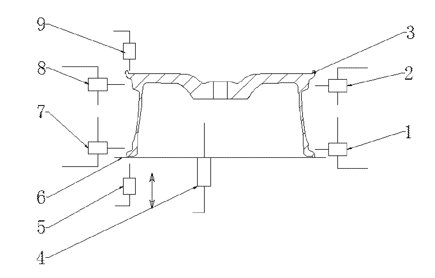
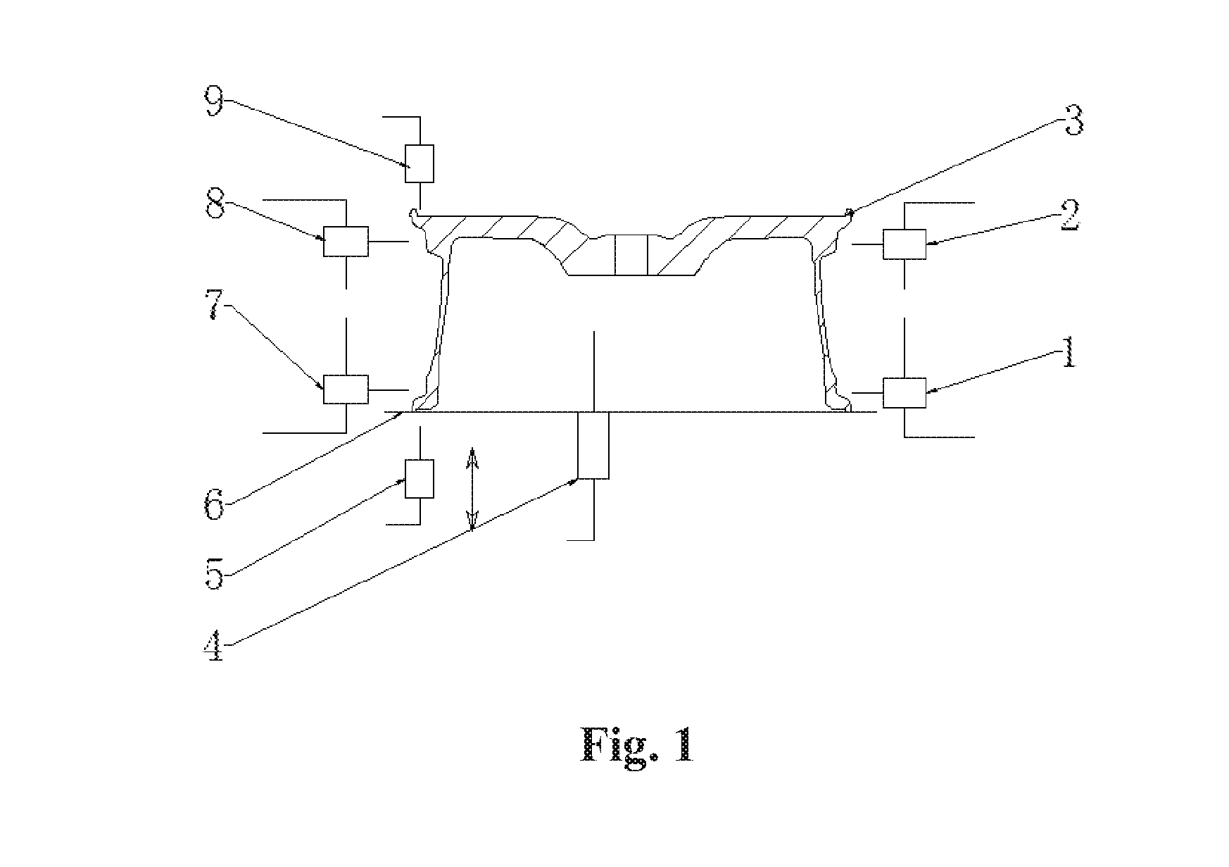
[0020] FIG. 1 is a structure schematic diagram of the automatic hub type identifying device during dimensional detection.
LIST OF REFERENCE SYMBOLS
[0021] 1--first servo drive and micro contact displacement detecting device, 2--second servo drive and micro contact displacement detecting device, 3--hub, 4--third servo drive and micro contact displacement detecting device, 5--fourth servo drive and micro contact displacement detecting device, 6--roller bed, 7--fifth servo drive and micro contact displacement detecting device, 8--sixth servo drive and micro contact displacement detecting device, 9--seventh servo drive and micro contact displacement detecting device.
DETAILED DESCRIPTION
First Embodiment: An Automatic Hub Type Identifying Device
[0022] The automatic hub type identifying device will be described in detail below in combination with the accompanying drawings.
[0023] The automatic hub type identifying device includes a servo drive and micro contact displacement detecting device 1, a servo drive and micro contact displacement detecting device 2, a hub 3, a servo drive and micro contact displacement detecting device 4, a servo drive and micro contact displacement detecting device 5, a roller bed 6, a servo drive and micro contact displacement detecting device 7, a servo drive and micro contact displacement detecting device 8, a servo drive and micro contact displacement detecting device 9 and an electronic belt scale.
[0024] The hub 3 on the roller bed 6 is first weighed by the electronic belt scale of the automatic hub type identifying device, roughly identified and positioned, that is, different hub types are distinguished by weight.
[0025] When the roughly identified hub 3 runs to an automatic dimensional measurement station, the hub 3 stops moving, and the servo drive devices 1, 2, 4, 5, 7, 8 and 9 drive micro contact measuring displacement sensors to measure the diameters of inner and outer bead seats of the hub 3, the width of the hub and the distance from the inner rim of the hub 3 to the flange face. The servo drive devices 1, 7 and the servo drive devices 2, 8 are equipped with industrial cameras for position identification of the bead seat of the hub 3; the servo drive devices 1, 7 drive the micro contact sensors to measure two points spacing a 180.degree. phase angle on the same circumference as the bead seat of the hub 3, and the measured data is the diameter of the inner bead seat of the hub 3; meanwhile, the micro contact measuring sensors on the servo drives 2, 8 are spaced a 180.degree. phase angle from the same circumference of the outer bead seat of the hub 3 for detection, and the measured data is the diameter of the outer bead seat of the hub 3.
[0026] Meanwhile, the servo drive devices 5, 9 drive the micro contact measuring sensors thereon to contact the inner and outer rims of the hub 3, and the width of the hub 3 is calculated through the displacement.
[0027] The servo drive device 4 drives the micro contact measuring sensor thereon to contact the inner flange face of the hub 3, the distance from the flange face to the inner edge of the hub 3 can be measured, and the offset value ET of the hub 3 is obtained by calculation.
[0028] Thus, the weight of the hub 3, the diameters of the inner and outer bead seats and the offset ET are compared with the data stored in an industrial computer to determine the unique type of the hub.
Second Embodiment: An Automatic Hub Type Identifying Device
[0029] As described in first Embodiment, after different types of hubs 3 are preliminarily weighed by the electronic belt scale and identified, the weight of the hub 3 is compared with the data in the database of the industrial computer for rough analysis, then the hub 3 is positioned, the diameter, width and offset ET of the hub 3 are detected, and the unique type of the hub 3 is determined according to the preset criteria.
[0030] For example, the weight of the hub 3 is measured to give a weight fluctuation range of .+-.100 g; the diameter of the hub 3 is measured to allow a variation range of nominal diameter D.+-.0.01 mm; the allowable fluctuation range of the width is W.+-.0.01 mm; the allowable fluctuation range of the offset ET is E.+-.0.1 mm; thus, the weight of the hub and the dimensions D, W, E are sequentially input into a comparison parameter table of the industrial computer according to the parameters of different hub types, and the data obtained by the detection are sequentially compared according to the table lookup method to obtain a corresponding hub type.
[0031] In this way, the hubs that are easily confused in weight can also be identified and distinguished according to the dimensional difference to achieve the purpose of hub identification.
[0032] By testing and verifying 10,000 different types of hubs, the identification device and method can realize 0 error identification, which fundamentally solves the problem of hub type identification error.
* * * * *
D00000
D00001
XML
uspto.report is an independent third-party trademark research tool that is not affiliated, endorsed, or sponsored by the United States Patent and Trademark Office (USPTO) or any other governmental organization. The information provided by uspto.report is based on publicly available data at the time of writing and is intended for informational purposes only.
While we strive to provide accurate and up-to-date information, we do not guarantee the accuracy, completeness, reliability, or suitability of the information displayed on this site. The use of this site is at your own risk. Any reliance you place on such information is therefore strictly at your own risk.
All official trademark data, including owner information, should be verified by visiting the official USPTO website at www.uspto.gov. This site is not intended to replace professional legal advice and should not be used as a substitute for consulting with a legal professional who is knowledgeable about trademark law.