Water-cooled Mold For Low-pressure Casting Of Aluminum Alloy Wheel
ZHU; Lin ; et al.
U.S. patent application number 16/204003 was filed with the patent office on 2019-09-26 for water-cooled mold for low-pressure casting of aluminum alloy wheel. The applicant listed for this patent is CITIC Dicastal CO., LTD.. Invention is credited to Changhai LI, Hongbiao Li, Baojun Shi, Lin ZHU.
| Application Number | 20190291173 16/204003 |
| Document ID | / |
| Family ID | 62898236 |
| Filed Date | 2019-09-26 |
| United States Patent Application | 20190291173 |
| Kind Code | A1 |
| ZHU; Lin ; et al. | September 26, 2019 |
WATER-COOLED MOLD FOR LOW-PRESSURE CASTING OF ALUMINUM ALLOY WHEEL
Abstract
A water-cooled mold for low-pressure casting of an aluminum alloy wheel includes an upper mold, a lower mold and a side mold which surround a cavity of aluminum alloy, in which a cooling insert is embedded into a side mold frame of the side mold; an upper parting surface, a lower parting surface and a side parting surface of the cooling insert are respectively in contact parting with the side mold frame, the side parting surface includes a front zone and a rear straight zone, and a gap of 1.5-2.5 mm is formed between the rear straight zone and the side mold frame.
| Inventors: | ZHU; Lin; (Qinhuangdao, CN) ; LI; Changhai; (Qinhuangdao, CN) ; Li; Hongbiao; (Qinhuangdao, CN) ; Shi; Baojun; (Qinhuangdao, CN) | ||||||||||
| Applicant: |
|
||||||||||
|---|---|---|---|---|---|---|---|---|---|---|---|
| Family ID: | 62898236 | ||||||||||
| Appl. No.: | 16/204003 | ||||||||||
| Filed: | November 29, 2018 |
| Current U.S. Class: | 1/1 |
| Current CPC Class: | C22C 21/00 20130101; B22C 9/28 20130101; B22D 18/04 20130101; B22C 9/065 20130101; B22D 27/04 20130101 |
| International Class: | B22C 9/06 20060101 B22C009/06; B22C 9/28 20060101 B22C009/28; B22D 18/04 20060101 B22D018/04; B22D 27/04 20060101 B22D027/04; C22C 21/00 20060101 C22C021/00 |
Foreign Application Data
| Date | Code | Application Number |
|---|---|---|
| Mar 23, 2018 | CN | 201810242568.2 |
Claims
1. A water-cooled mold for low-pressure casting of an aluminum alloy wheel, a water-cooled side mold comprising an upper mold, a lower mold and a side mold which surround a cavity of aluminum alloy, wherein a cooling insert is embedded into a side mold frame of the side mold; an upper parting surface, a lower parting surface and a side parting surface of the cooling insert are respectively in contact parting with the side mold frame, the side parting surface comprises a front zone and a rear straight zone, and a gap of 1.5-2.5 mm is formed between the rear straight zone and the side mold frame; remaining zones of the upper parting surface and the lower parting surface are 0.15-0.25 mm away from the side mold frame except 10-15 mm wide assembly zones; a cooling water channel is provided inside the cooling insert, and inlet and outlet joints are arranged at two ends of the cooling water channel.
2. The water-cooled mold for low-pressure casting of an aluminum alloy wheel according to claim 1, wherein a gap of 2 mm is formed between the rear straight zone and the side mold frame, and the remaining zones of the upper parting surface and the lower parting surface are 0.20 mm away from the side mold frame except 12 mm wide assembly zones.
3. The water-cooled mold for low-pressure casting of an aluminum alloy wheel according to claim 1, wherein the cooling insert is fixed to the side mold frame by screws.
4. The water-cooled mold for low-pressure casting of an aluminum alloy wheel according to claim 1, wherein the cooling insert is provided with blind hole insulating grooves toward spokes of the mold.
5. The water-cooled mold for low-pressure casting of an aluminum alloy wheel according to claim 1, wherein the cooling insert is provided with through hole insulating grooves toward a window of the mold.
6. The water-cooled mold for low-pressure casting of an aluminum alloy wheel according to claim 1, wherein the cooling insert comprises a sealing baffle outside the cooling water channel.
7. The water-cooled mold for low-pressure casting of an aluminum alloy wheel according to claim 1, wherein the cooling water channel provided inside the cooling insert causes cooling water to flow from bottom to top.
Description
CROSS-REFERENCE TO RELATED APPLICATIONS
[0001] The present application claims benefit of Chinese Patent Application No. 201810242568.2, filed on Mar. 23, 2018, the contents of which are hereby incorporated by reference in its entirety.
BACKGROUND
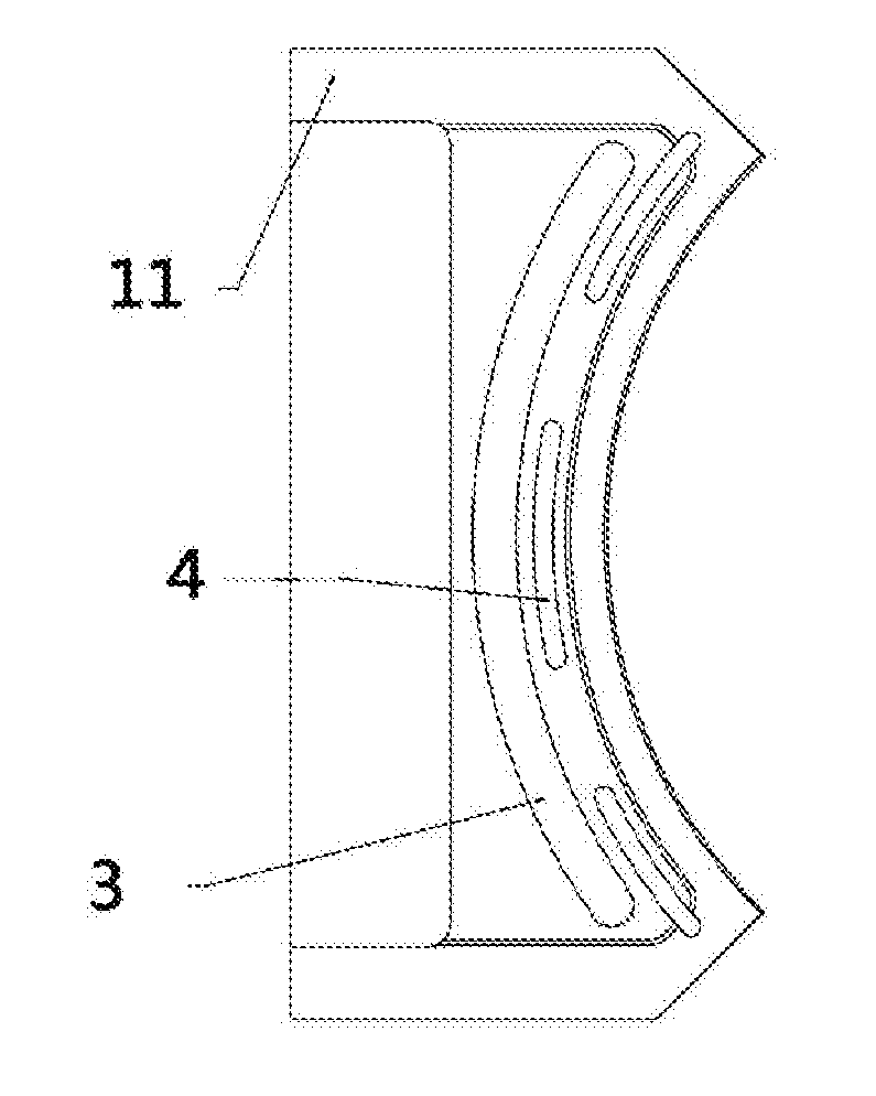
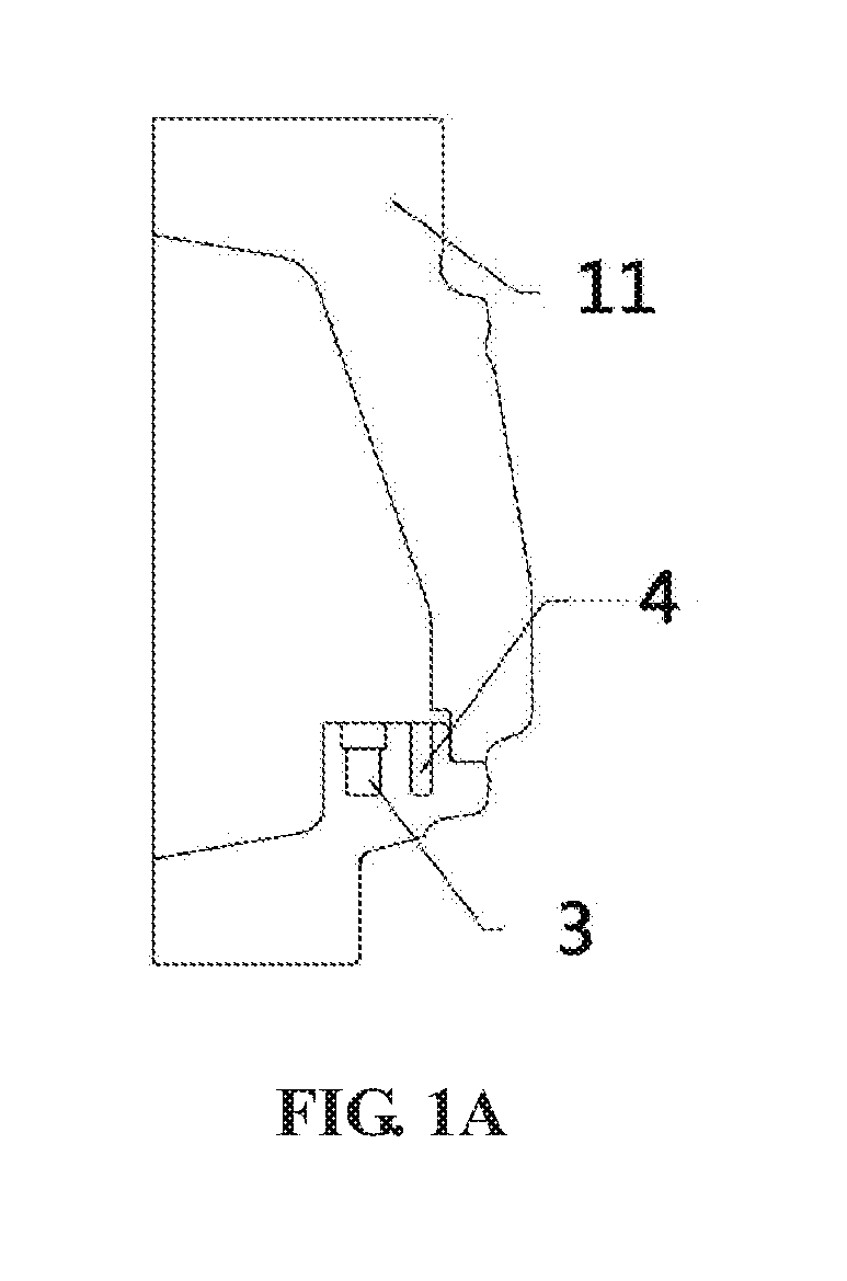
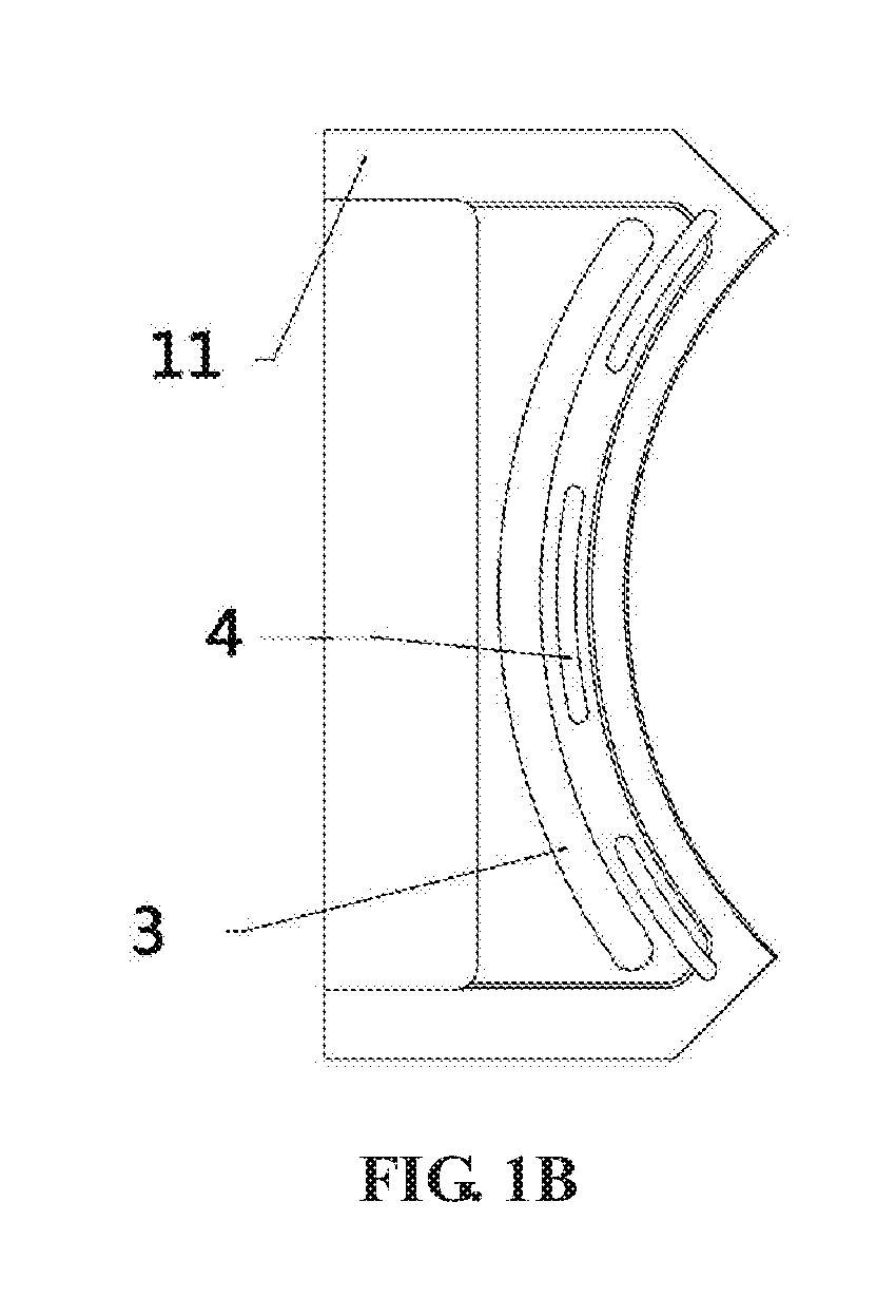
[0002] In the automobile part industry, the requirements for the appearance and performance of wheels as special parts, especially for the performance of spokes, are extremely stringent. In aluminum wheel enterprises, the performance of the spokes is usually improved by strengthening side mold cooling. This method is repeatedly used and effective in air-cooled molds. However, counterproductive effects often occur in water-cooled molds, and the root cause is the unreasonable design of the side mold water-cooling structure. FIGS. 1A-1B show schematic diagrams of a side mold water-cooling structure of a conventional water-cooled mold. The cooling water channel is opened downward, and the insulating groove is only opened to the window zone and is a blind hole insulating groove, which inevitably causes the side mold cooling effect to be stronger at the lower part than at the upper part, so that the shrinkage porosity easily occurs at the roots of the spokes when the side mold cooling opening time is slightly long or the flow rate is slightly large. The present disclosure will provide an improved side mold water-cooling structure to solve the current problems.
SUMMARY
[0003] The present disclosure relates to the field of low-pressure casting of aluminum alloy, and specifically, relates to a water-cooled mold for low-pressure casting of an aluminum alloy wheel.
[0004] Accordingly, the object of the present disclosure is to provide a water-cooled mold for low-pressure casting of an aluminum alloy wheel.
[0005] In one aspect of the present disclosure, provided is a water-cooled mold for low-pressure casting of an aluminum alloy wheel, the water-cooled side mold including an upper mold, a lower mold and a side mold which surround a cavity of aluminum alloy, in which a cooling insert is embedded into a side mold frame of the side mold; an upper parting surface, a lower parting surface and a side parting surface of the cooling insert are respectively in contact parting with the side mold frame, the side parting surface includes a front zone and a rear straight zone, and a gap of 1.5-2.5 mm is formed between the rear straight zone and the side mold frame; the remaining zones of the upper parting surface and the lower parting surface are 0.15-0.25 mm away from the side mold frame except 10-15 mm wide assembly zones; a cooling water channel is provided inside the cooling insert, and inlet and outlet joints are arranged at two ends of the cooling water channel.
[0006] In a preferred aspect of the present disclosure, a gap of 2 mm is formed between the rear straight zone and the side mold frame, and the remaining zones of the upper parting surface and the lower parting surface are 0.20 mm away from the side mold frame except 12 mm wide assembly zones.
[0007] In a preferred aspect of the present disclosure, the cooling insert is fixed to the side mold frame by screws.
[0008] In a preferred aspect of the present disclosure, the cooling insert is provided with blind hole insulating grooves toward spokes of the mold.
[0009] In a preferred aspect of the present disclosure, the cooling insert is provided with through hole insulating grooves toward a window of the mold.
[0010] In a preferred aspect of the present disclosure, the cooling insert includes a sealing baffle outside the cooling water channel.
[0011] In a preferred aspect of the present disclosure, the cooling water channel provided inside the cooling insert causes cooling water to flow from bottom to top.
[0012] The advantages of the present disclosure are as follows: the cooling water channel is designed into a straight channel to balance the temperature difference between the center and two sides of the side mold and reduce the thermal deformation of the mold; the 0.2 mm clearance of the upper and lower parting surfaces can control the cooling range of the side mold and improve the permeability of the mold; the cooling range of the side mold can be further controlled through the cooperation of the blind hole and through hole insulation grooves; and the water-cooling insert is embedded, which can prolong the life of the mold and reduce the cost of the mold.
BRIEF DESCRIPTION OF DRAWINGS
[0013] The embodiments of the present disclosure will be described in detail below in combination with the accompanying drawings, in which:
[0014] The present disclosure and specific embodiments will be further described below in combination with the accompanying drawings.
[0015] FIGS. 1A-1B are schematic diagrams of a side mold water-cooling structure of a conventional water-cooled mold, FIG. 1A is a cross-sectional view of a side mold, and FIG. 1B is a top view of the side mold;
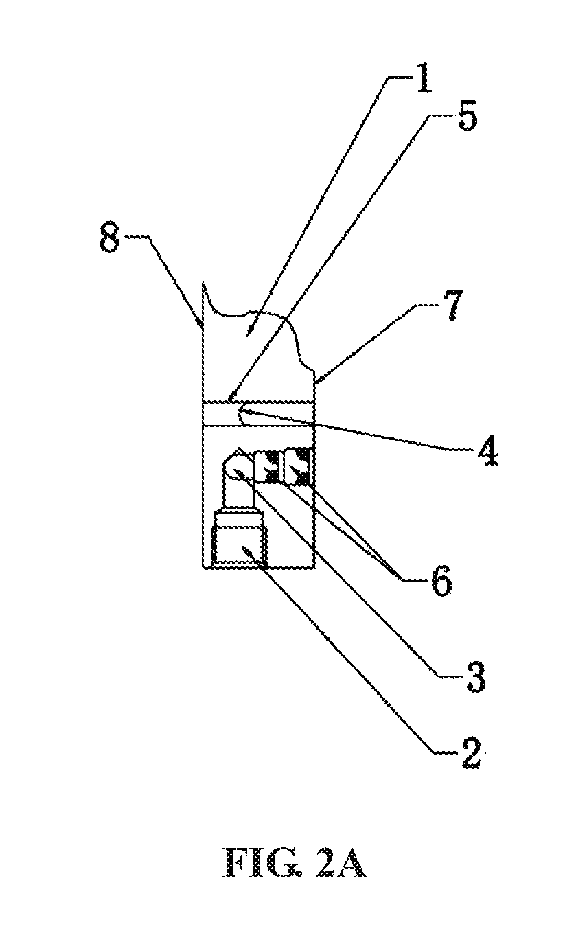
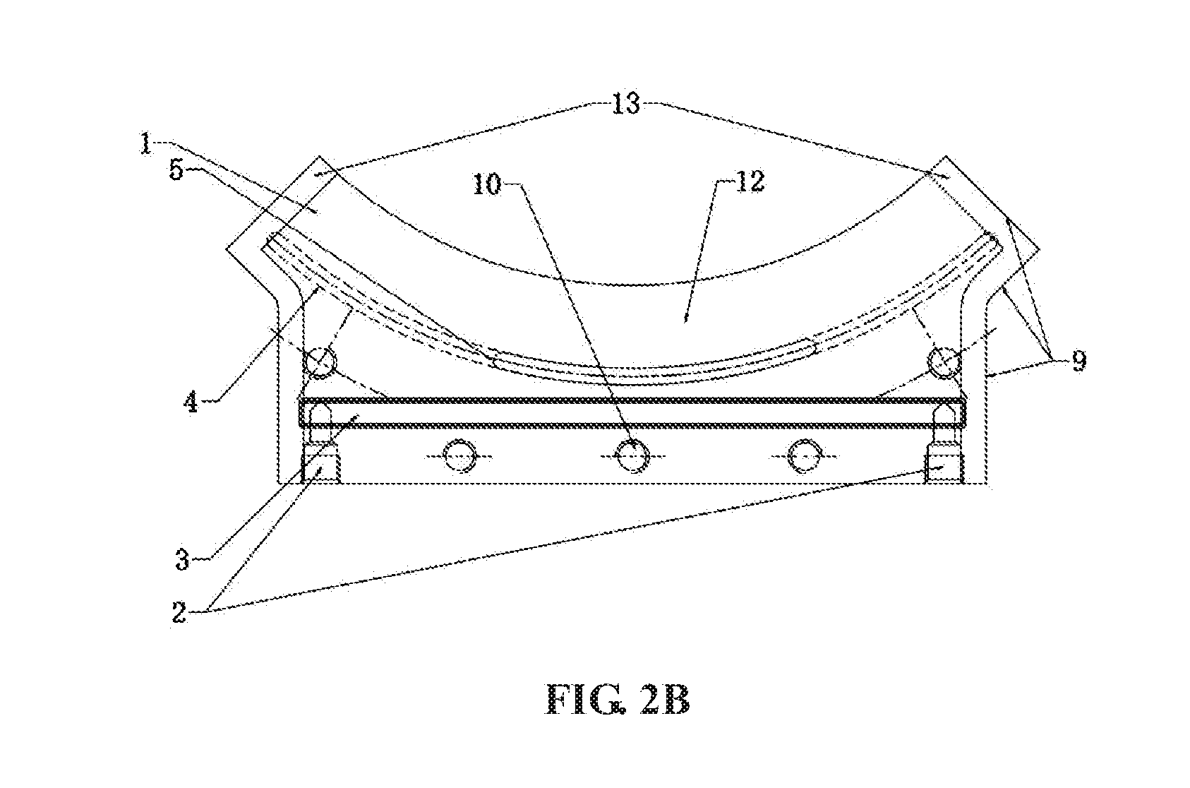
[0016] FIGS. 2A-2B are schematic diagrams of an improved side mold water-cooling structure, FIG. 2A is a cross-sectional view of a side mold, and FIG. 2B is a top view of the side mold;
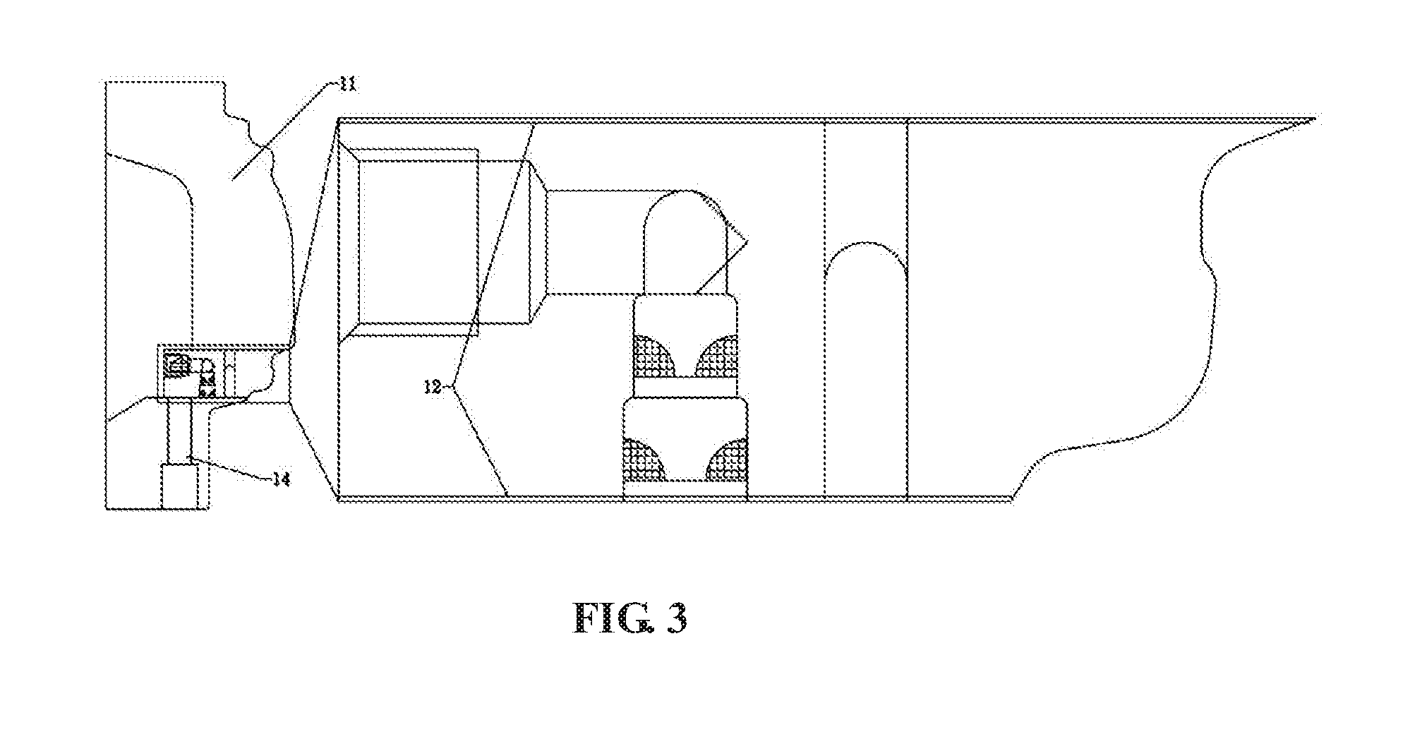
[0017] FIG. 3 is an assembly diagram of the improved side mold water-cooling structure and a partial enlarged view thereof.
LIST OF REFERENCE SYMBOLS
[0018] 1 cooling insert [0019] 2 inlet and outlet joint mounting hole [0020] 3 cooling water channel [0021] 4 blind hole insulating groove [0022] 5 through hole insulating groove [0023] 6 double sealing baffle [0024] 7 lower parting surface [0025] 8 upper parting surface [0026] 9 side parting surface [0027] 10 bolt hole [0028] 11 side mold frame [0029] 12 cooling insert clearance zone [0030] 13 assembly surface between the upper parting surface and the lower parting surface [0031] 14 through hole
DETAILED DESCRIPTION
[0032] The improved side mold water-cooling structure of the present disclosure includes a cooling insert 1 and a side mold frame 11.
[0033] First, the cooling insert 1 and the side mold frame 11 of corresponding sizes are machined in accordance with the requirements of the drawing. A 0.2 mm clearance zone 12 is machined on an upper parting surface 8 and a lower parting surface 7 of the cooling insert 1, except 10-15 mm assembly surfaces 13 reserved on two sides.
[0034] Then, bolt holes 10 are machined in the cooling insert 1, and through holes 14 are machined in the side mold frame 11.
[0035] Finally, a cooling water channel 3, blind hole insulating grooves 4, through hole insulating grooves 5, and a double sealing baffle 6 for sealing are machined on the cooling insert 1. The sealing baffle is snapped into the cooling water channel 3 and fixed by welding.
[0036] After the above operation is completed, the cooling insert 1 can be inserted into the side mold frame 11, and screws penetrate through the through holes 14 in the side mold frame and are screwed into the bolt holes 10 in the cooling insert 1.
* * * * *
D00000
D00001
D00002
D00003
D00004
D00005
XML
uspto.report is an independent third-party trademark research tool that is not affiliated, endorsed, or sponsored by the United States Patent and Trademark Office (USPTO) or any other governmental organization. The information provided by uspto.report is based on publicly available data at the time of writing and is intended for informational purposes only.
While we strive to provide accurate and up-to-date information, we do not guarantee the accuracy, completeness, reliability, or suitability of the information displayed on this site. The use of this site is at your own risk. Any reliance you place on such information is therefore strictly at your own risk.
All official trademark data, including owner information, should be verified by visiting the official USPTO website at www.uspto.gov. This site is not intended to replace professional legal advice and should not be used as a substitute for consulting with a legal professional who is knowledgeable about trademark law.