Treadmill Folding Device Having Locking Function And Method For Using The Same
REN; YANG-JIE
U.S. patent application number 16/361492 was filed with the patent office on 2019-09-26 for treadmill folding device having locking function and method for using the same. The applicant listed for this patent is XIAMEN OHYEAH TECHNOLOGY CO., LTD.. Invention is credited to YANG-JIE REN.
| Application Number | 20190290956 16/361492 |
| Document ID | / |
| Family ID | 62847682 |
| Filed Date | 2019-09-26 |


View All Diagrams
| United States Patent Application | 20190290956 |
| Kind Code | A1 |
| REN; YANG-JIE | September 26, 2019 |
TREADMILL FOLDING DEVICE HAVING LOCKING FUNCTION AND METHOD FOR USING THE SAME
Abstract
A treadmill folding device having a locking function includes a treadmill deck, a first upright pole, a control panel and a first lockable telescopic mechanism. The control panel is mounted to an upper end of the first upright pole. A lower end of the first upright pole is movably connected to a side of the treadmill deck. The first lockable telescopic mechanism is connected between a middle portion of the first upright pole and the side of the treadmill deck. The first upright pole, the treadmill deck and the first lockable telescopic mechanism form a triangular area when the first lockable telescopic mechanism is in an extended state. The first upright pole is parallel to or about parallel to the treadmill deck when the first lockable telescopic mechanism is in a retracted state.
| Inventors: | REN; YANG-JIE; (XIAMEN, CN) | ||||||||||
| Applicant: |
|
||||||||||
|---|---|---|---|---|---|---|---|---|---|---|---|
| Family ID: | 62847682 | ||||||||||
| Appl. No.: | 16/361492 | ||||||||||
| Filed: | March 22, 2019 |
| Current U.S. Class: | 1/1 |
| Current CPC Class: | A63B 22/02 20130101; A63B 2210/58 20130101; A63B 71/023 20130101; A63B 2210/50 20130101; A63B 22/0235 20130101 |
| International Class: | A63B 22/02 20060101 A63B022/02; A63B 71/02 20060101 A63B071/02 |
Foreign Application Data
| Date | Code | Application Number |
|---|---|---|
| Mar 26, 2018 | CN | 201810253212.9 |
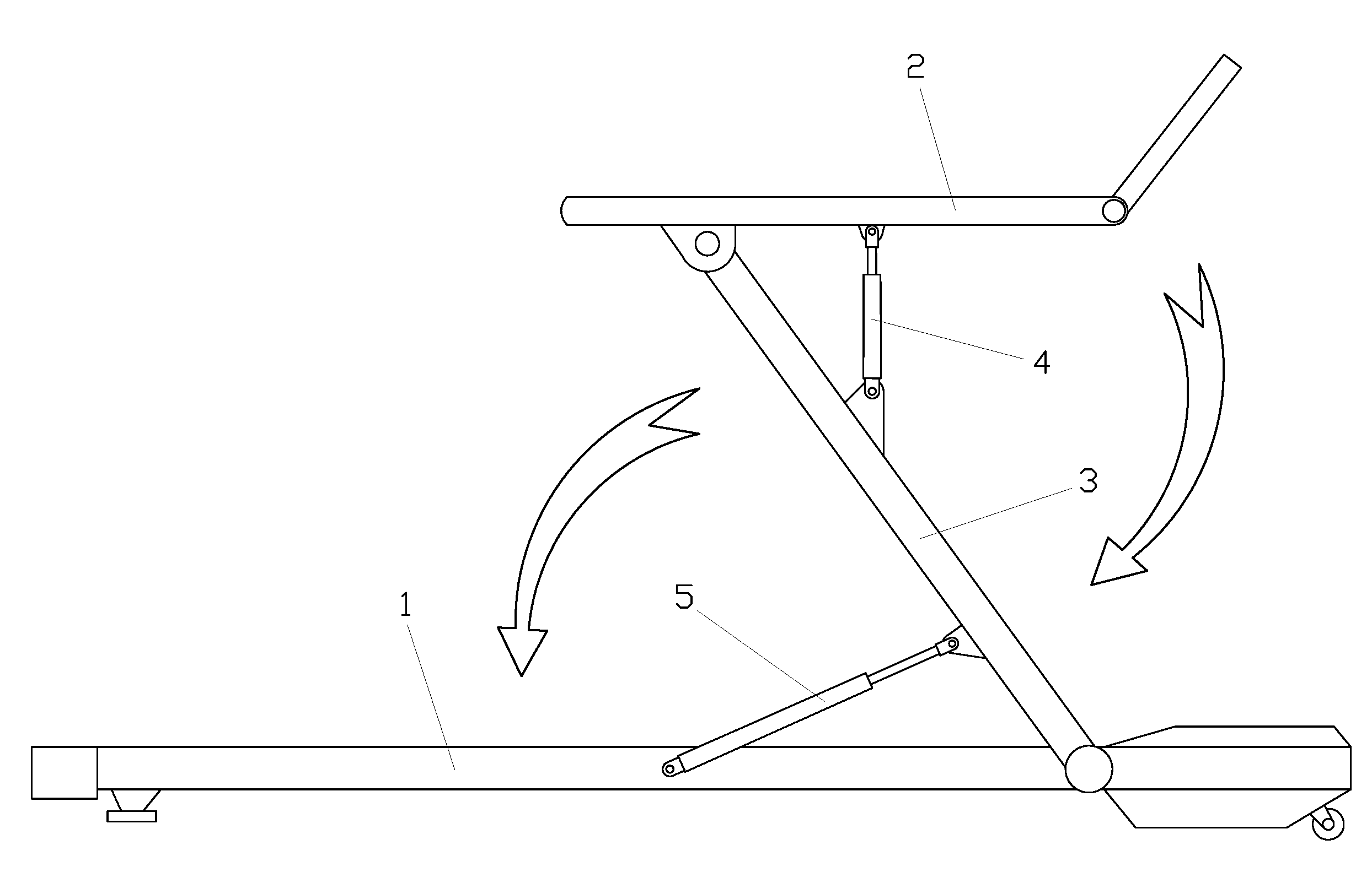
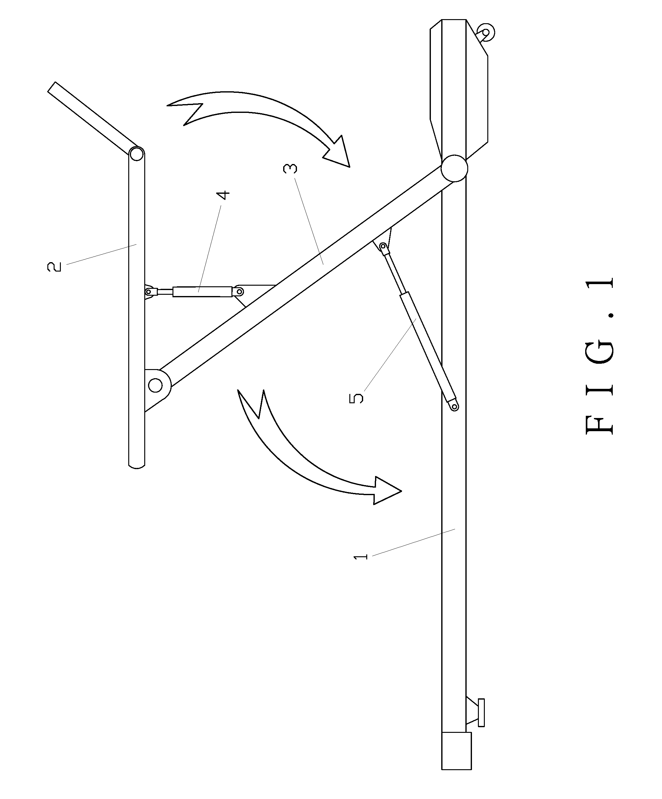
Claims
1. A treadmill folding device having a locking function, comprising a treadmill deck, a first upright pole, a control panel and a first lockable telescopic mechanism, the control panel being mounted to an upper end of the first upright pole, a lower end of the first upright pole being movably connected to a side of the treadmill deck, the first upright pole being rotatable forward and backward relative to the treadmill deck, the first lockable telescopic mechanism being connected between a middle portion of the first upright pole and the side of the treadmill deck, wherein the first upright pole, the treadmill deck and the first lockable telescopic mechanism form a triangular area when the first lockable telescopic mechanism is in an extended state; wherein the first upright pole is parallel to or about parallel to the treadmill deck when the first lockable telescopic mechanism is in a retracted state.
2. The treadmill folding device as claimed in claim 1, further comprising a second lockable telescopic mechanism, a rear end of the control panel being movably connected to the upper end of the first upright pole, the control panel being rotatable forward and backward relative to the first upright pole, the second lockable telescopic mechanism being hingedly connected between an underside of a middle portion of the control panel and a front side of the middle portion of the first upright pole.
3. The treadmill folding device as claimed in claim 1, further comprising a second lockable telescopic mechanism, a front end of the control panel being movably connected to the upper end of the first upright pole, the control panel being rotatable forward and backward relative to the first upright pole, the second lockable telescopic mechanism being hingedly connected between an underside of a middle portion of the control panel and a rear side of the middle portion of the first upright pole.
4. The treadmill folding device as claimed in claim 1, further comprising a second upright pole, a front end of the control panel being movably connected to the upper end of the first upright pole, the control panel being rotatable forward and backward relative to the first upright pole, the second upright pole being hingedly connected between a middle portion of the control panel and the side of the treadmill deck, the treadmill deck, the control panel, the first upright pole and the second upright pole forming a parallelogram mechanism.
5. The treadmill folding device as claimed in claim 1, further comprising a second upright pole, a middle portion of the control panel being movably connected to the upper end of the first upright pole, the control panel being rotatable forward and backward relative to the first upright pole, the second upright pole being hingedly connected between a front portion of the control panel and the side of the treadmill deck, the treadmill deck, the control panel, the first upright pole and the second upright pole forming a parallelogram mechanism.
6. The treadmill folding device as claimed in claim 1, wherein the first lockable telescopic mechanism includes one of a self-locking traction gas spring, a hydraulic cylinder, a pneumatic cylinder and an electric push rod.
7. The treadmill folding device as claimed in claim 2, wherein the second lockable telescopic mechanism includes one of a self-locking traction gas spring, a hydraulic cylinder, a pneumatic cylinder and an electric push rod.
8. The treadmill folding device as claimed in claim 3, wherein the second lockable telescopic mechanism includes one of a self-locking traction gas spring, a hydraulic cylinder, a pneumatic cylinder and an electric push rod.
9. The treadmill folding device as claimed in claim 6, wherein the self-locking traction gas spring includes a cylinder barrel, a piston, a piston rod, a needle valve, and an end cap, the piston is disposed in the cylinder barrel, the piston is sealedly slidably fitted in the cylinder barrel, the end cap is mounted at an opening of the cylinder barrel, the piston is fixedly connected to an inner end of the piston rod, the piston rod extends outward from a central hole of the end cap, a sealing ring is provided between an outer side wall of the piston rod and an inner side wall of the end cap, a rodless chamber of the cylinder barrel is provided with oil, a rod chamber of the cylinder barrel is provided with a gas, the needle valve is disposed in the piston rod, a valve of the needle valve is disposed on the piston, and a switch of the needle valve is disposed at an outer end of the piston rod.
10. The treadmill folding device as claimed in claim 9, wherein the switch is an eccentric rotary switch, the eccentric rotary switch includes a rotary handle and a cam, the cam is rotatably mounted to the outer end of the piston rod, the rotary handle is fixedly connected to the cam, and the cam drives a needle rod of the needle valve to move up and down.
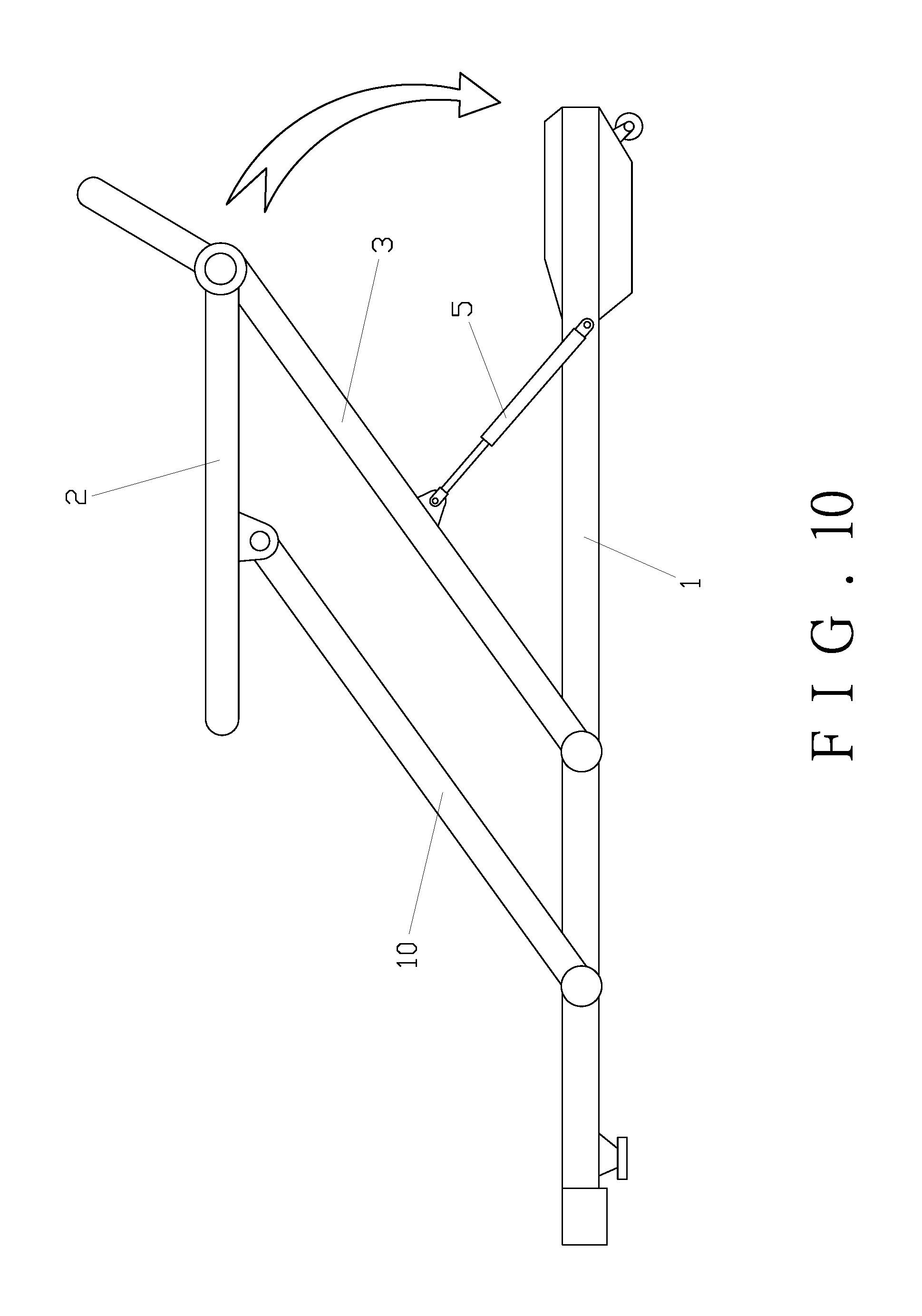
11. A method for using the treadmill folding device as claimed in claim 1, comprising: (1) folding downward: releasing the first lockable telescopic mechanism and retracting the first lockable telescopic mechanism for the first upright pole to be turned and folded relative to the treadmill deck to an ultimate storage state; (2) unfolding upward: extending the first lockable telescopic mechanism for the first upright pole to unfold automatically to an ultimate state and locking the first lockable telescopic mechanism.
Description
FIELD OF THE INVENTION
[0001] The present invention relates to a treadmill, and more particularly to a treadmill folding device having a locking function and a method for using the same.
BACKGROUND OF THE INVENTION
[0002] A treadmill is a common fitness apparatus for a family or gym. It is the simplest of home fitness equipment, and is the best choice for home fitness equipment. The upright poles of the existing treadmills are generally permanently fixed, cannot be folded and stored, and occupy a large space when not in use. The design of the treadmill is unwise and inconvenient. Accordingly, the inventor of the present invention has devoted himself based on his many years of practical experiences to solve these problems.
SUMMARY OF THE INVENTION
[0003] In view of the above shortcomings of the prior art, the primary object of the present invention is to provide a treadmill folding device having a locking function and a method for using the same.
[0004] According to one aspect of the present invention, a treadmill folding device having a locking function is provided. The treadmill folding device comprises a treadmill deck, a first upright pole, a control panel, and a first lockable telescopic mechanism. The control panel is mounted to an upper end of the first upright pole. A lower end of the first upright pole is movably connected to a side of the treadmill deck. The first upright pole is rotatable forward and backward relative to the treadmill deck. The first lockable telescopic mechanism is connected between a middle portion of the first upright pole and the side of the treadmill deck. The first upright pole, the treadmill deck and the first lockable telescopic mechanism form a triangular area when the first lockable telescopic mechanism is in an extended state. The first upright pole is parallel to or about parallel to the treadmill deck when the first lockable telescopic mechanism is in a retracted state.
[0005] Preferably, the treadmill folding device further comprises a second lockable telescopic mechanism. A rear end of the control panel is movably connected to the upper end of the first upright pole. The control panel is rotatable forward and backward relative to the first upright pole. The second lockable telescopic mechanism is hingedly connected between an underside of a middle portion of the control panel and a front side of the middle portion of the first upright pole.
[0006] Alternatively, the treadmill folding device further comprises a second lockable telescopic mechanism. A front end of the control panel is movably connected to the upper end of the first upright pole. The control panel is rotatable forward and backward relative to the first upright pole. The second lockable telescopic mechanism is hingedly connected between an underside of a middle portion of the control panel and a rear side of the middle portion of the first upright pole.
[0007] Preferably, the treadmill folding device further comprises a second upright pole. A front end of the control panel is movably connected to the upper end of the first upright pole. The control panel is rotatable forward and backward relative to the first upright pole. The second upright pole is hingedly connected between a middle portion of the control panel and the side of the treadmill deck. The treadmill deck, the control panel, the first upright pole and the second upright pole form a parallelogram mechanism.
[0008] Alternatively, the treadmill folding device further comprises a second upright pole. A middle portion of the control panel is movably connected to the upper end of the first upright pole. The control panel is rotatable forward and backward relative to the first upright pole. The second upright pole is hingedly connected between a front portion of the control panel and the side of the treadmill deck. The treadmill deck, the control panel, the first upright pole and the second upright pole form a parallelogram mechanism.
[0009] Preferably, the first lockable telescopic mechanism includes one of a self-locking traction gas spring, a hydraulic cylinder, a pneumatic cylinder and an electric push rod.
[0010] Preferably, the second lockable telescopic mechanism includes one of a self-locking traction gas spring, a hydraulic cylinder, a pneumatic cylinder and an electric push rod.
[0011] Preferably, the self-locking traction gas spring includes a cylinder barrel, a piston, a piston rod, a needle valve, and an end cap. The piston is disposed in the cylinder barrel. The piston is sealedly slidably fitted in the cylinder barrel. The end cap is mounted at an opening of the cylinder barrel. The piston is fixedly connected to an inner end of the piston rod. The piston rod extends outward from a central hole of the end cap. A sealing ring is provided between an outer side wall of the piston rod and an inner side wall of the end cap. A rodless chamber of the cylinder barrel is provided with oil. A rod chamber of the cylinder barrel is provided with a gas. The needle valve is disposed in the piston rod. A valve of the needle valve is disposed on the piston. A switch of the needle valve is disposed at an outer end of the piston rod.
[0012] Preferably, the switch is an eccentric rotary switch. The eccentric rotary switch includes a rotary handle and a cam. The cam is rotatably mounted to the outer end of the piston rod. The rotary handle is fixedly connected to the cam. The cam drives a needle rod of the needle valve to move up and down.
[0013] According to another aspect of the present invention, a method for using the treadmill folding device is provided. The method comprises (1) folding downward: releasing the first lockable telescopic mechanism and retracting the first lockable telescopic mechanism for the first upright pole to be turned and folded relative to the treadmill deck to an ultimate storage state; (2) unfolding upward: extending the first lockable telescopic mechanism for the first upright pole to unfold automatically to an ultimate state and locking the first lockable telescopic mechanism.
[0014] According to the above technical features, the following effects can be achieved:
[0015] 1. The present invention utilizes the characteristics that the lockable telescopic mechanisms are extendable and retractable and can be controlled by rotating the handles of the switches, so the treadmill is more convenient and flexible to be folded and stored and can be locked by the switches to meet the safety requirements of the bearing capacity of the whole equipment. It is more stable and reliable when it is unfolded, and occupies less space when it is folded and stored, and saves packaging materials.
[0016] 2. The first upright poles and the second upright poles are in a tightly balanced state when they are folded and stored. Even if there is a vibration generated by the transportation of the equipment, it does not lead to vibration noises generated by the first upright poles, the second upright poles and the control panel.
BRIEF DESCRIPTION OF THE DRAWINGS
[0017] FIG. 1 is a schematic view in accordance with a first embodiment of the present invention;
[0018] FIG. 2 is a perspective view in accordance with the first embodiment of the present invention in an unfolded state;
[0019] FIG. 3 is a side view in accordance with the first embodiment of the present invention in an unfolded state;
[0020] FIG. 4 is a perspective view in accordance with the first embodiment of the present invention in a folded state;
[0021] FIG. 5 is a side view in accordance with the first embodiment of the present invention in a folded state;
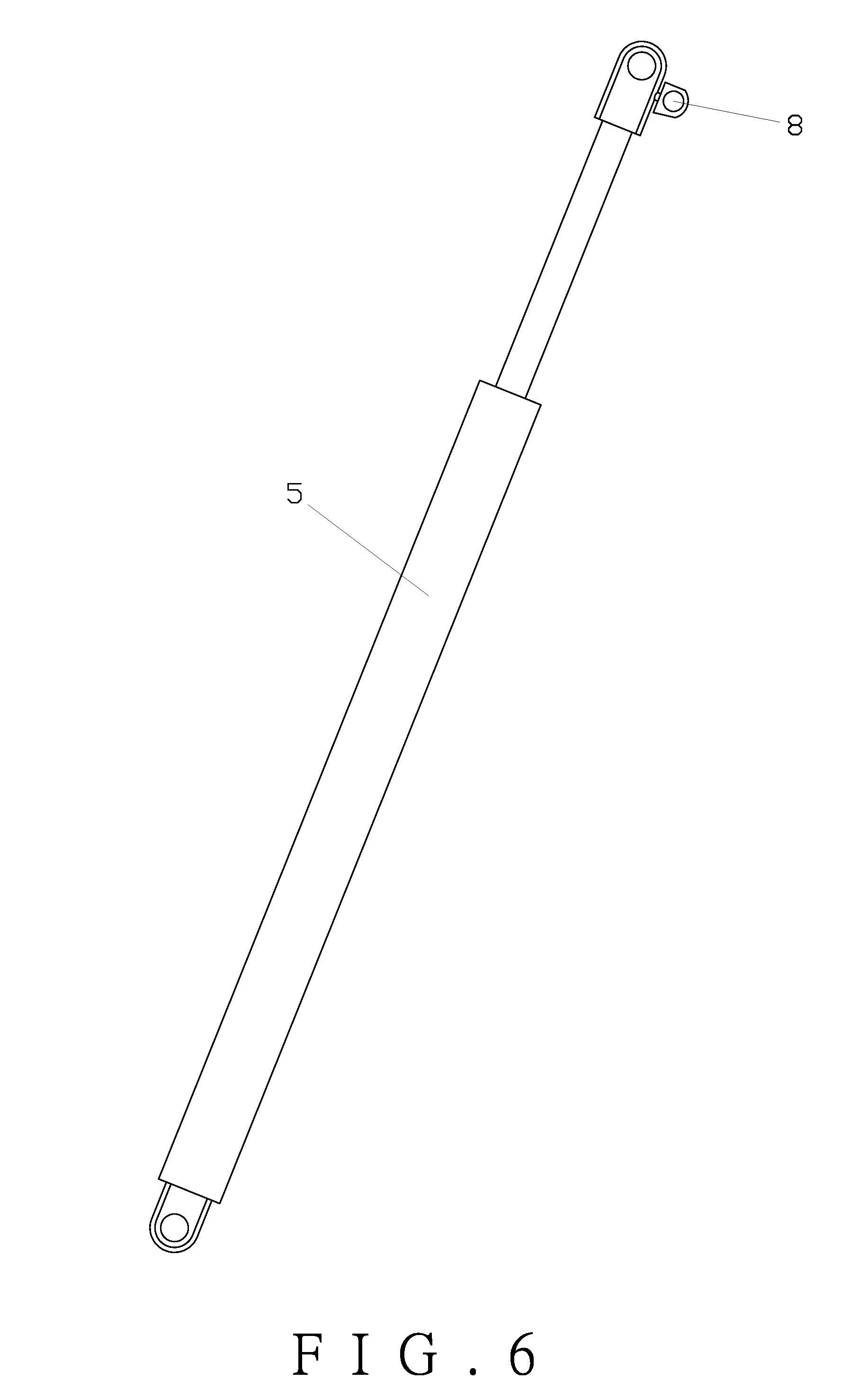
[0022] FIG. 6 is a schematic view showing the external structure of the self-locking traction gas spring;
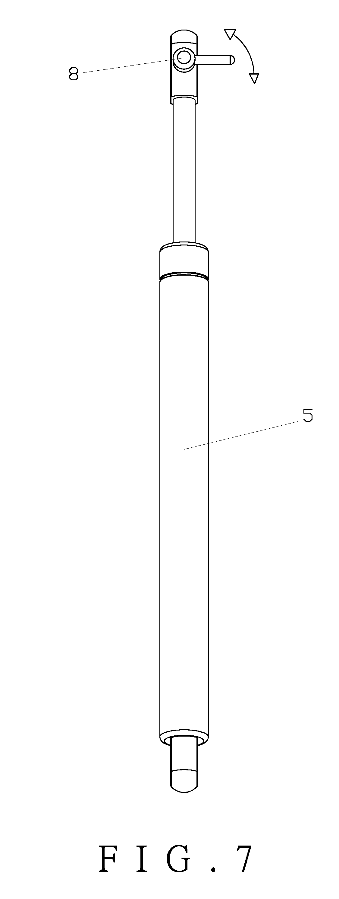
[0023] FIG. 7 is a schematic view showing the rotation of the switch of the self-locking traction gas spring;
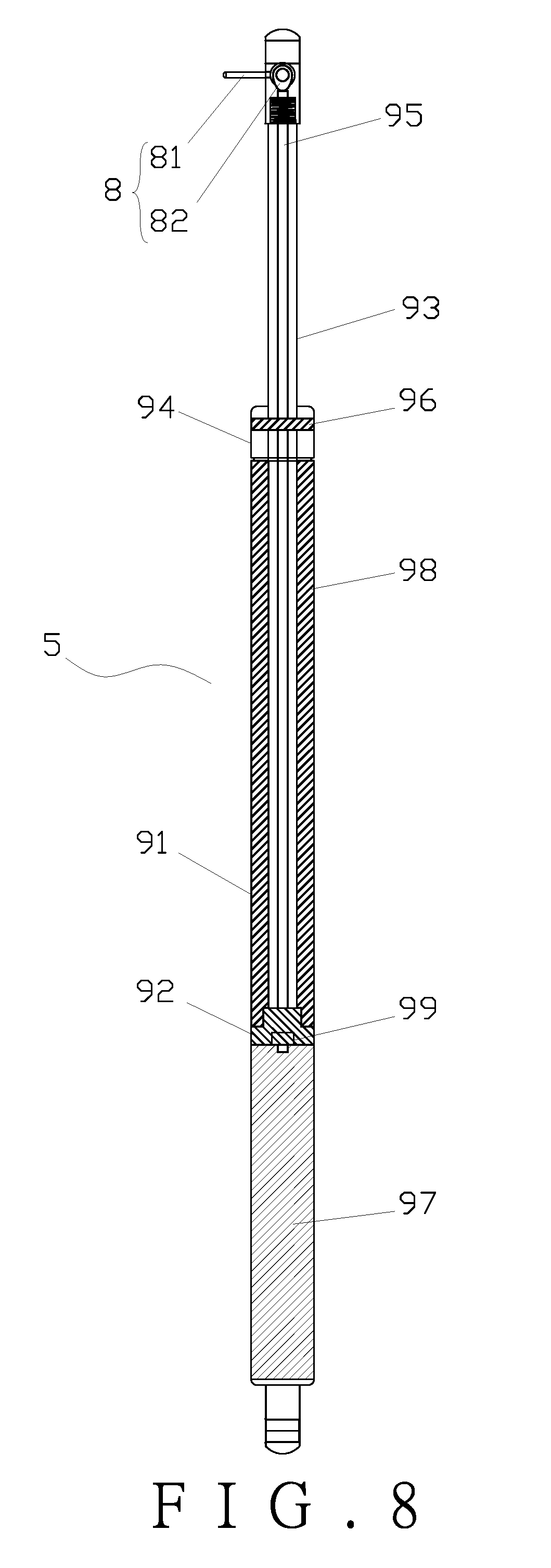
[0024] FIG. 8 is a schematic view showing the internal structure of the self-locking traction gas spring;
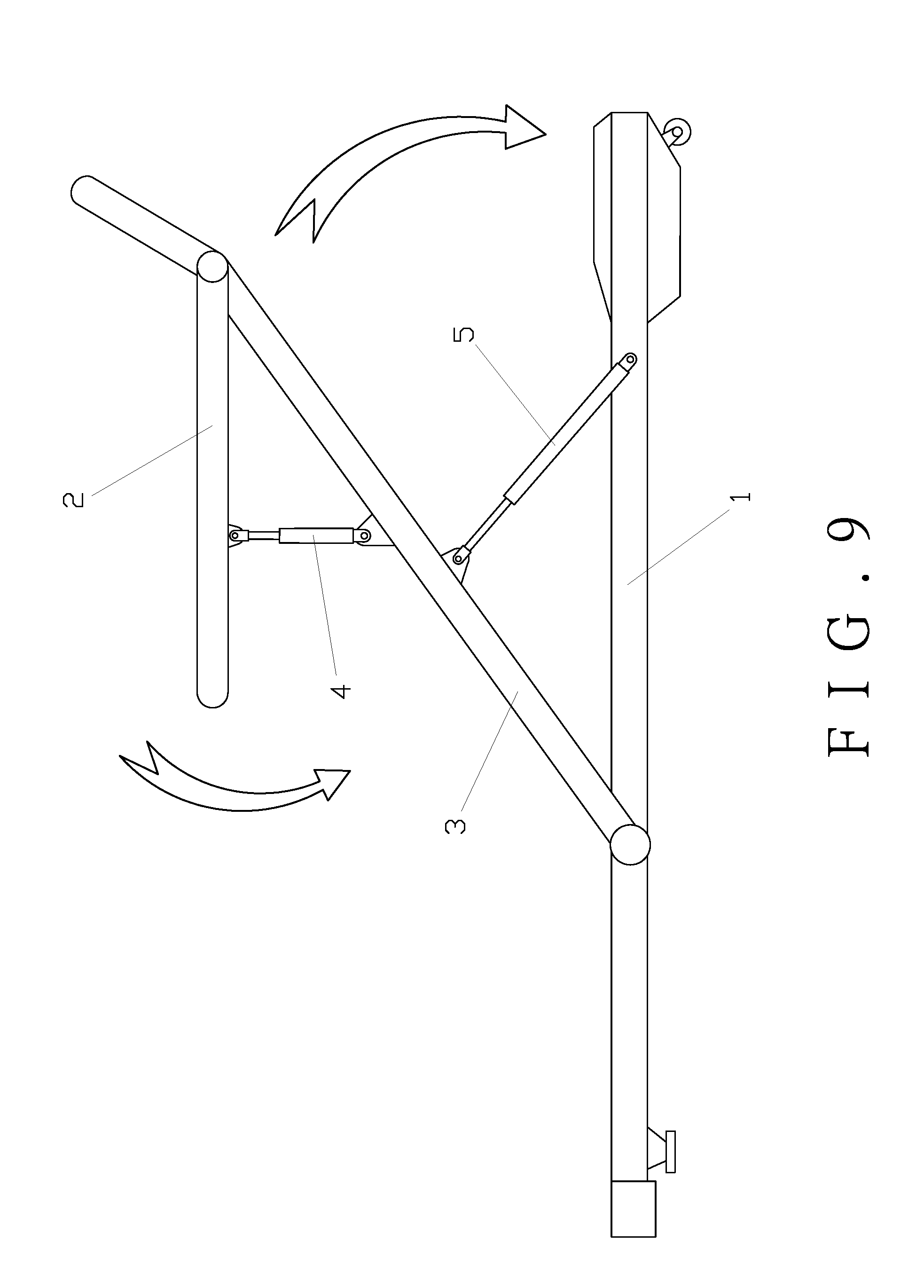
[0025] FIG. 9 is a schematic view in accordance with a second embodiment of the present invention;
[0026] FIG. 10 is a schematic view in accordance with a third embodiment of the present invention; and
[0027] FIG. 11 is a schematic view in accordance with a fourth embodiment of the present invention.
DETAILED DESCRIPTION OF THE PREFERRED EMBODIMENTS
[0028] Embodiments of the present invention will now be described, by way of example only, with reference to the accompanying drawings.
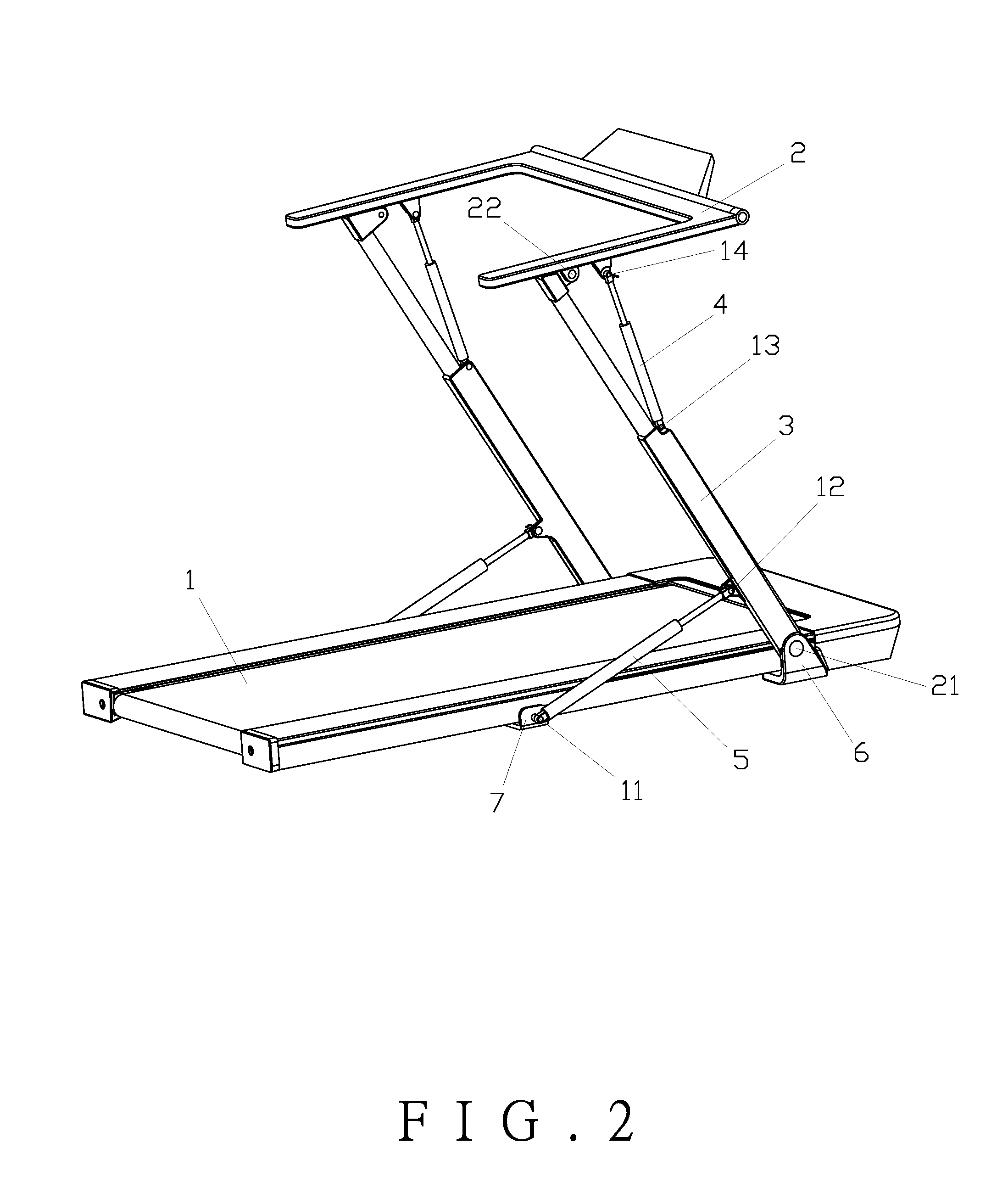
[0029] Referring to FIG. 1 through FIG. 8, a treadmill folding device having a locking function in accordance with a first embodiment of the present invention comprises a treadmill deck 1, a plurality of first upright poles 3, a control panel 2, two first lockable telescopic mechanisms 5, and two second lockable telescopic mechanisms 4. The control panel 2 is mounted to the upper ends of the first upright poles 3. The lower ends of the first upright poles 3 are movably connected to two sides of the treadmill deck 1, respectively. The first upright poles 3 are rotatable forward and backward relative to the treadmill deck 1. The first lockable telescopic mechanisms 5 ae symmetrically connected between the middle portions of the first upright poles 3 and the two sides of the treadmill deck 1, respectively. A corresponding one of the first upright poles 3, the treadmill deck 1 and a corresponding one of the first lockable telescopic mechanisms 5 form a triangular area when the first lockable telescopic mechanisms 5 are in an extended state, so that the first upright poles 3 can stand stably when unfolded. The first upright poles 3 are parallel to or about parallel to the treadmill deck 1 when the first lockable telescopic mechanisms 5 are in a retracted state.
[0030] In the first embodiment, the lower ends of the first upright poles 3 are hingedly connected to the two sides of the front portion of the treadmill deck 1, respectively. The first lockable telescopic mechanisms 5 are hingedly connected between the rear sides of the middle portions of the first upright poles 3 and the two sides of the middle portion of the treadmill deck 1, respectively. The rear end of the control panel 2 is movably connected to the upper ends of the first upright poles 3, and the control panel 2 is rotatable forward and backward relative to the first upright poles 3. The second lockable telescopic mechanisms 4 ae symmetrically hinged between the underside of the middle portion of the control panel 2 and the front sides of the middle portions of the first upright poles 3, respectively.
[0031] In the first embodiment, as shown in FIG. 8, the first lockable telescopic mechanisms 5 and the second lockable telescopic mechanisms 4 are self-locking traction gas springs. Of course, it is possible to use a telescopic mechanism with a locking function, such as a hydraulic cylinder, a pneumatic cylinder or an electric push rod. This embodiment is described by taking the first lockable telescopic mechanism 5 as a representative. The self-locking traction gas spring is adopted, but not limited to the following structure, including a cylinder barrel 91, a piston 92, a piston rod 93, a needle valve, and an end cap 94. The piston 92 is disposed in the cylinder barrel 91, and the piston 92 is sealedly slidably fitted in the cylinder barrel 91. The end cap 94 is mounted at an opening of the cylinder barrel 91. The piston 92 is fixedly connected to the inner end of the piston rod 93. The piston rod 93 extends outward from a central hole of the end cap 94. A sealing ring 96 is provided between an outer side wall of the piston rod 93 and an inner side wall of the end cap 94. A rodless chamber of the cylinder barrel 91 is provided with oil 97. A rod chamber of the cylinder barrel 91 is provided with a gas 98. The needle valve is disposed in the piston rod 93. A valve 99 of the needle valve is disposed on the piston 92. A switch 8 of the needle valve is disposed at the outer end of the piston rod 93.
[0032] In the first embodiment, the switch 8 is an eccentric rotary switch. The eccentric rotary switch includes a rotary handle 81 and a cam 82. The cam 82 is rotatably mounted to the outer end of the piston rod 93. The rotary handle 81 is fixedly connected to the cam 82. The cam 82 drives a needle rod 95 of the needle valve to move up and down. By rotating the rotary handle 81, the cam 82 drives the needle rod 95 to push and pull for opening and closing the valve 99 on the piston 92. When the valve 99 is opened, the first lockable telescopic mechanism 5 is compressed by an external force. When the valve 99 is closed, the first lockable telescopic mechanism 5 is locked.
[0033] In the first embodiment, a pair of first support blocks 6 is fixedly disposed below the two sides of the front portion of the treadmill deck 1. The first support blocks 6 each have a first articulated lug bent upward. The lower ends of the first upright poles 3 are rotatably connected to the two first articulated lugs through a plurality of rotating shafts to form two first pivot points 21, respectively. A pair of second support blocks 7 is fixedly disposed below the two sides of the middle portion of the treadmill deck 1. The second support blocks 7 each have a second articulated lug bent upward. The cylinder ends of the two first lockable telescopic mechanisms 5 are rotatably connected to the two second articulated lugs through a plurality of rotating shafts to form two first fulcrums 11, respectively.
[0034] In the first embodiment, the rear sides of the lower portions of the first upright poles 3 are provided with first articulated seats, respectively. The piston rod ends of the two first lockable telescopic mechanisms 5 are rotatably connected to the two first articulated seats through a plurality of rotating shafts to form two second fulcrums 12, respectively. The front sides of the middle portions of the first upright poles 3 are provided with second articulated seats, respectively. The cylinder ends of the two second lockable telescopic mechanisms 4 are rotatably connected to the two second articulated seats through a plurality of rotating shafts to form two third fulcrums 13, respectively.
[0035] In the first embodiment, the two sides of the underside of the middle portion of the control panel 2 are provided with third articulated seats, respectively. The piston rod ends of the two second lockable telescopic mechanisms 4 are rotatably connected to the two third articulated seats through a plurality of rotating shafts to form two fourth fulcrums 14, respectively.
[0036] In the first embodiment, the two sides of the underside of the rear portion of the control panel 2 are provided with fourth articulated seats, respectively. The front sides of the upper ends of the first upright poles 3 are provided with fifth articulated seats, respectively. The two fifth articulated seats are rotatably connected to the two fourth articulated seats through a plurality of rotating shafts to form two second pivot points 22, respectively.
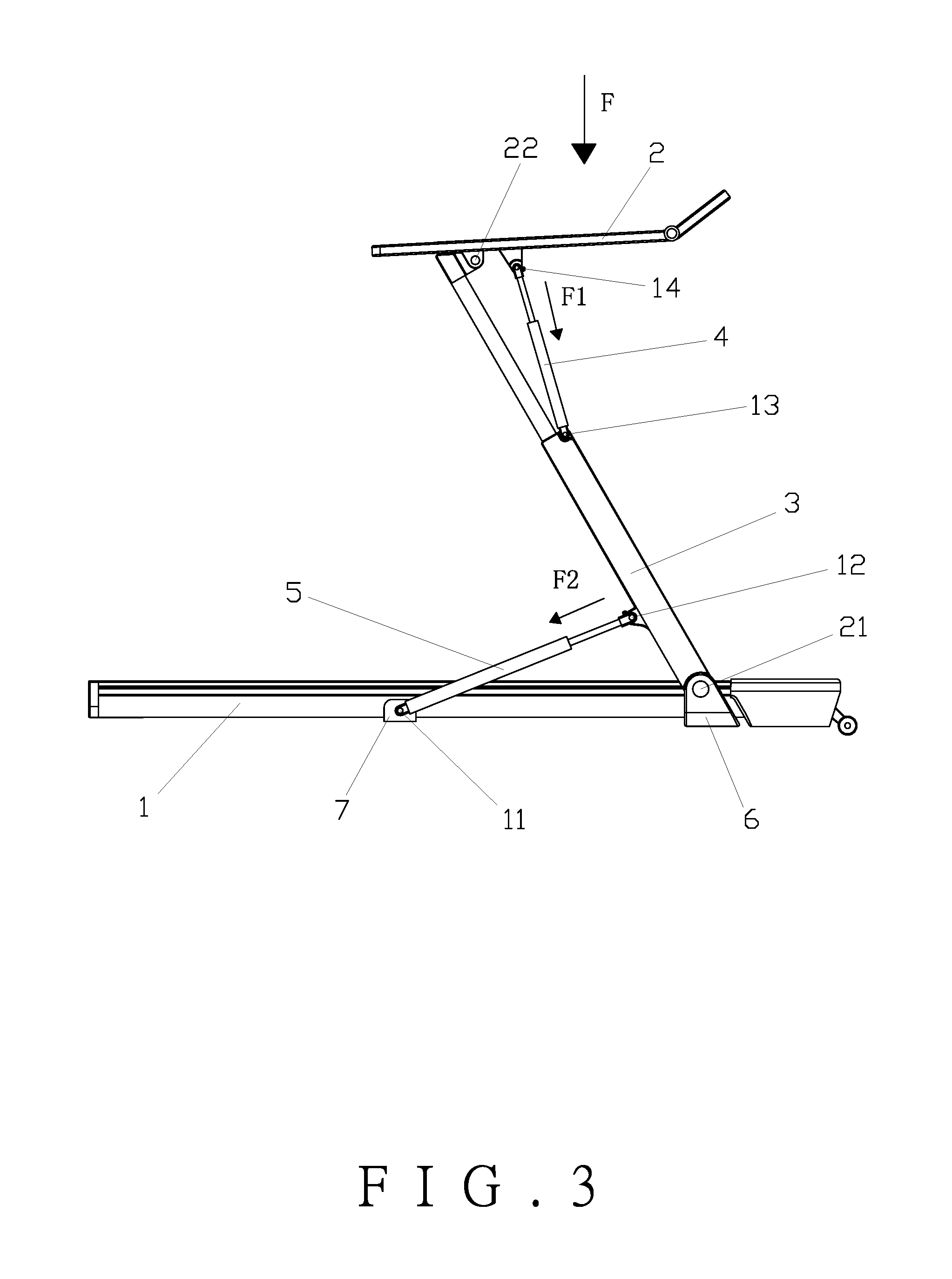
[0037] As shown in FIG. 1 to FIG. 5, a method for using the aforesaid treadmill folding device having a locking function comprises: (1) folding downward: the second lockable telescopic mechanisms 4 and the first lockable telescopic mechanisms 5 are first released by the respective switches 8, and then the control panel 2 is pressed downward with a force F. In this way, the control panel 2 presses the second lockable telescopic mechanisms 4 downward with a force F1 to be turned and folded relative to the first upright poles 3 to an ultimate state parallel to the first upright poles 3. Then, the first upright poles 3 with the control panel 2 press the first lockable telescopic mechanisms 5 obliquely downward with a force F2 to be turned and folded relative to the treadmill deck 1 to the ultimate storage state. The arrow in FIG. 1 indicates the folding direction. (2) unfolding upward: the control panel 2 is first lifted to a predetermined angle with a predetermined force, such that the second lockable telescopic mechanisms 4 and the first lockable telescopic mechanisms 5 are extended automatically, enabling the control panel 2 and the first upright poles 3 to unfold automatically to their respective ultimate states, and then the second lockable telescopic mechanisms 4 and the first lockable telescopic mechanisms 5 are locked by the respective switches 8. The treadmill is generally Z-shaped after being unfolded.
[0038] The first embodiment of the present invention utilizes the characteristics that the lockable telescopic mechanisms are extendable and retractable and can be controlled by rotating the handles of the switches 8 manually, so the treadmill is more convenient and flexible to be folded and stored and can be locked by the switches 8 to meet the safety requirements of the bearing capacity of the whole equipment. It is more stable and reliable when it is unfolded, and occupies less space when it is folded and stored, and saves packaging materials. The first upright poles 3 are in a tightly balanced state when they are folded and stored. Even if there is a vibration generated by the transportation of the equipment, it does not lead to vibration noises generated by the first upright poles 3 and the control panel 2.
[0039] FIG. 9 illustrates a second embodiment of the present invention, which is substantially similar to the first embodiment with the exceptions described hereinafter. The lower ends of the first upright poles 3 are hingedly connected to the two sides of the middle portion of the treadmill deck 1, respectively. The first lockable telescopic mechanisms 5 are hingedly connected between the front sides of the middle portions of the first upright poles 3 and the two sides of the front portion of the treadmill deck 1, respectively. The front end of the control panel 2 is movably connected to the upper ends of the first upright poles 3, and the control panel 2 is rotatable forward and backward relative to the first upright poles 3. The second lockable telescopic mechanisms 4 ae symmetrically hinged between the underside of the middle portion of the control panel 2 and the rear sides of the middle portions the first upright poles 3, respectively. The treadmill folding device having the locking function is used in the same manner as in the first embodiment, but has a reverse Z shape after being unfolded. The arrow in FIG. 9 indicates the folding direction.
[0040] Referring to FIG. 10, a treadmill folding device having a locking function in accordance with a third embodiment of the present invention comprises a treadmill deck 1, a plurality of first upright poles 3, a control panel 2, two first lockable telescopic mechanisms 5, and two second upright poles 10. The control panel 2 is mounted to the upper ends of the first upright poles 3. The lower ends of the first upright poles 3 are movably connected to two sides of the treadmill deck 1, respectively. The first upright poles 3 are rotatable forward and backward relative to the treadmill deck 1. The first lockable telescopic mechanisms 5 ae symmetrically connected between the middle portions of the first upright poles 3 and the two sides of the treadmill deck 1, respectively. A corresponding one of the first upright poles 3, the treadmill deck 1 and a corresponding one of the first lockable telescopic mechanisms 5 form a triangular area when the first lockable telescopic mechanisms 5 are in an extended state, so that the first upright poles 3 can stand stably when unfolded. The first upright poles 3 are parallel to or about parallel to the treadmill deck 1 when the first lockable telescopic mechanisms 5 are in a retracted state.
[0041] In the third embodiment, the lower ends of the first upright poles 3 are hingedly connected to the two sides of the middle portion of the treadmill deck 1, respectively. The first lockable telescopic mechanisms 5 ae hingedly connected between the front sides of the middle portions of the first upright poles 3 and the two sides of the front portion of the treadmill deck 1, respectively. The front end of the control panel 2 is movably connected to the upper ends of the first upright poles 3, and the control panel 2 is rotatable forward and backward relative to the first upright poles 3. The second upright poles 10 ae hingedly connected between the underside of the middle portion of the control panel 2 and the two sides of the rear portion of the treadmill deck 1, respectively. The treadmill deck 1, the control panel 2, the first upright poles 3 and the second upright poles 10 form a parallelogram mechanism.
[0042] In the third embodiment, the first lockable telescopic mechanisms 5 may be a telescopic mechanism with a locking function, such as a hydraulic cylinder, a pneumatic cylinder or an electric push rod. A method for using the treadmill folding device having a locking function comprises: (1) folding downward: the first lockable telescopic mechanisms 5 are first released, and then the control panel 2 is pressed downward with a force F. In this way, the control panel 2 presses the first upright poles 3 downward with a force F1 to be turned and folded relative to the second upright poles 10 to an ultimate state parallel to the first upright poles 3. Then, the first upright poles 3 with the control panel 2 press the first lockable telescopic mechanisms 5 obliquely downward with a force F2 to be turned and folded relative to the treadmill deck 1 to the ultimate storage state. The arrow in FIG. 10 indicates the folding direction. (2) unfolding upward: the first upright poles 3 and the second upright poles 10 are unfolded automatically to their respective ultimate states through the first lockable telescopic mechanisms 5, and then the first lockable telescopic mechanisms 5 are locked.
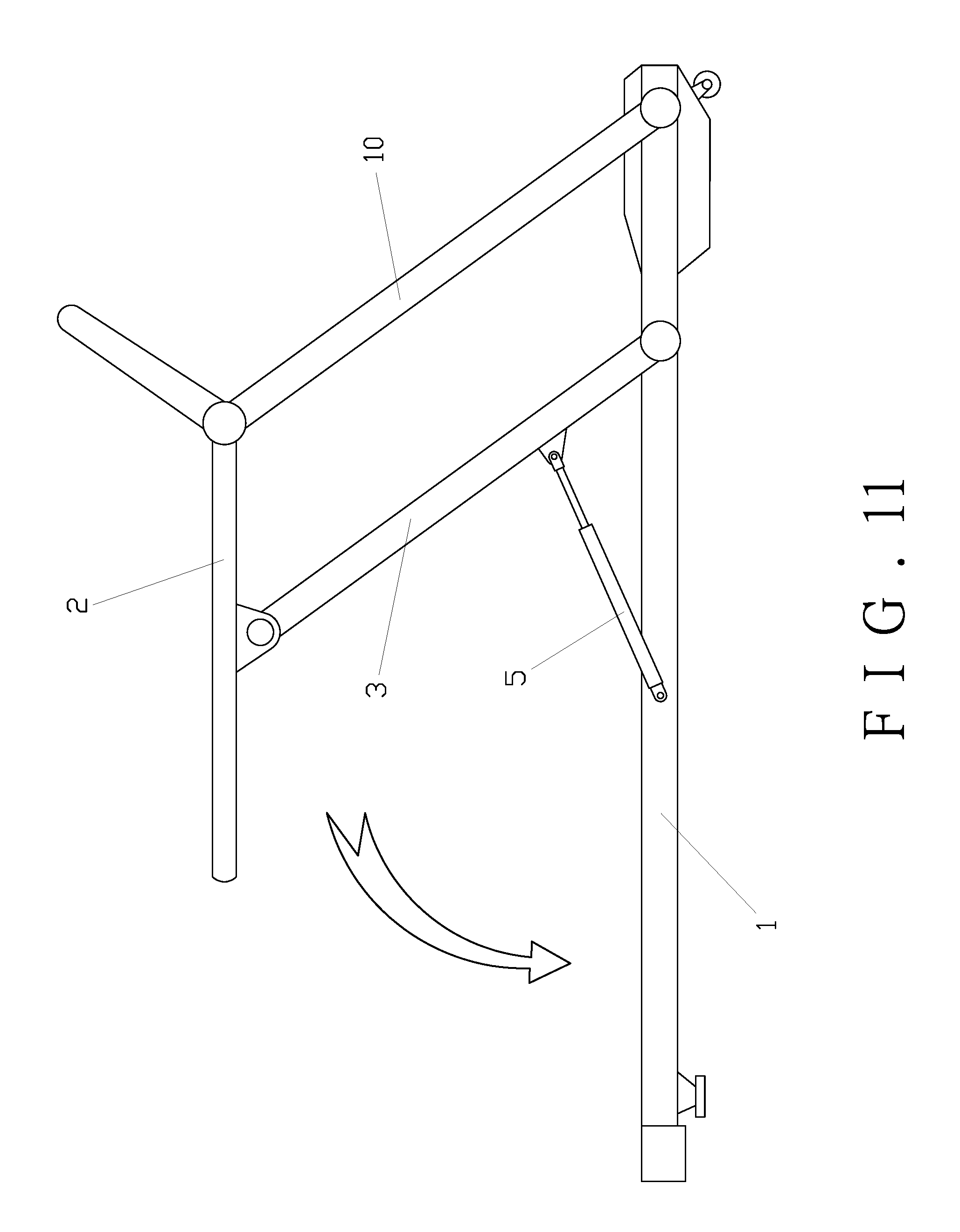
[0043] FIG. 11 illustrates a fourth embodiment of the present invention, which is substantially similar to the third embodiment with the exceptions described hereinafter. The lower ends of the first upright poles 3 are hingedly connected to the two sides of the front portion of the treadmill deck 1, respectively. The first lockable telescopic mechanisms 5 are hingedly connected between the rear sides of the middle portions of the first upright poles 3 and the two sides of the middle portion of the treadmill deck 1, respectively. The underside of the middle portion of the control panel 2 is movably connected to the upper ends of the first upright poles 3, and the control panel 2 is rotatable forward and backward relative to the first upright poles 3. The second upright poles 10 are hingedly connected between the front portion of the control panel 2 and the front portion of the treadmill deck 1, respectively. The treadmill deck 1, the control panel 2, the first upright poles 3 and the second upright poles 10 form a parallelogram mechanism. The treadmill folding device having the locking function is used in the same manner as in the third embodiment, but has a reverse configuration after being unfolded. The arrow in FIG. 11 indicates the folding direction.
[0044] Although particular embodiments of the present invention have been described in detail for purposes of illustration, various modifications and enhancements may be made without departing from the spirit and scope of the present invention. Accordingly, the present invention is not to be limited except as by the appended claims.
* * * * *
D00000
D00001
D00002
D00003
D00004
D00005
D00006
D00007
D00008
D00009
D00010
D00011
XML
uspto.report is an independent third-party trademark research tool that is not affiliated, endorsed, or sponsored by the United States Patent and Trademark Office (USPTO) or any other governmental organization. The information provided by uspto.report is based on publicly available data at the time of writing and is intended for informational purposes only.
While we strive to provide accurate and up-to-date information, we do not guarantee the accuracy, completeness, reliability, or suitability of the information displayed on this site. The use of this site is at your own risk. Any reliance you place on such information is therefore strictly at your own risk.
All official trademark data, including owner information, should be verified by visiting the official USPTO website at www.uspto.gov. This site is not intended to replace professional legal advice and should not be used as a substitute for consulting with a legal professional who is knowledgeable about trademark law.