Supraventricular Tachy Sensing Vector
Perschbacher; David L. ; et al.
U.S. patent application number 16/440367 was filed with the patent office on 2019-09-26 for supraventricular tachy sensing vector. The applicant listed for this patent is Cardiac Pacemakers, Inc.. Invention is credited to Ron A. Balczewski, James O. Gilkerson, David L. Perschbacher.
| Application Number | 20190290916 16/440367 |
| Document ID | / |
| Family ID | 40404967 |
| Filed Date | 2019-09-26 |
| United States Patent Application | 20190290916 |
| Kind Code | A1 |
| Perschbacher; David L. ; et al. | September 26, 2019 |
SUPRAVENTRICULAR TACHY SENSING VECTOR
Abstract
A system includes a pulse generator including a can electrode and a lead couplable to the pulse generator, the lead including a distal coil electrode and a proximal coil electrode, wherein both of the coil electrodes are electrically uncoupled from the can electrode such that a unipolar sensing vector is provided between at least one of the coil electrodes and the can electrode.
| Inventors: | Perschbacher; David L.; (Coon Rapids, MN) ; Gilkerson; James O.; (Stillwater, MN) ; Balczewski; Ron A.; (Bloomington, MN) | ||||||||||
| Applicant: |
|
||||||||||
|---|---|---|---|---|---|---|---|---|---|---|---|
| Family ID: | 40404967 | ||||||||||
| Appl. No.: | 16/440367 | ||||||||||
| Filed: | June 13, 2019 |
Related U.S. Patent Documents
| Application Number | Filing Date | Patent Number | ||
|---|---|---|---|---|
| 15265674 | Sep 14, 2016 | 10350419 | ||
| 16440367 | ||||
| 12277101 | Nov 24, 2008 | |||
| 15265674 | ||||
| 61007635 | Dec 13, 2007 | |||
| Current U.S. Class: | 1/1 |
| Current CPC Class: | A61B 5/0464 20130101; A61N 1/3622 20130101; A61N 1/3925 20130101; A61N 1/36592 20130101; A61N 1/39622 20170801; A61N 1/3702 20130101; A61B 5/04011 20130101 |
| International Class: | A61N 1/37 20060101 A61N001/37; A61N 1/365 20060101 A61N001/365; A61B 5/0464 20060101 A61B005/0464; A61B 5/04 20060101 A61B005/04; A61N 1/39 20060101 A61N001/39; A61N 1/362 20060101 A61N001/362 |
Claims
1. A method comprising: receiving, using a pulse generator, first cardiac electrical information from a first unipolar sensing vector between a distal coil electrode of a lead and a can electrode of the pulse generator electrically isolated from the distal coil electrode; receiving, using the pulse generator, second cardiac electrical information from a second unipolar sensing vector between a proximal coil electrode of the lead and the can electrode of the pulse generator electrically isolated from the proximal coil electrode; and determining, using the pulse generator, a cardiac rhythm using the received first and second cardiac electrical information.
2. The method of claim 1, wherein determining the cardiac rhythm comprises distinguishing between ventricular tachycardia (VT) and supraventricular tachycardia (SVT) using the received first and second cardiac electrical information.
3. The method of claim 1, further including receiving, using the pulse generator third cardiac electrical information from a third sensing vector between the distal coil electrode and the proximal coil electrode.
4. The method of claim 1, wherein the pulse generator is configured such that the first unipolar sensing vector between the distal coil electrode and the can electrode and the second unipolar sensing vector between the proximal electrode and the can electrode occur simultaneously.
5. The method of claim 1, wherein the pulse generator is configured such that the first unipolar sensing vector between the distal coil electrode and the can electrode and the second unipolar sensing vector between the proximal electrode and the can electrode are sensed alternately.
6. The method of claim 1, wherein determining the cardiac rhythm comprises distinguishing between ventricular tachycardia (VT) and supraventricular tachycardia (SVT) using the received first and second cardiac electrical information by using a template of the correlation between shock vector electrograms and RV rate vector electrograms during normal sinus rhythm.
7. The method of claim 6, wherein determining the cardiac rhythm includes comparing the template to an on-going rhythm and if the ongoing rhythm matches the template, the pulse generator decides that the origin of the rhythm is supraventricular
8. The method of claim 7, wherein if the on-going rhythm does not match the template, the pulse generator decides that the rhythm is VT.
9. The method of claim 8, further including receiving, using the pulse generator third cardiac electrical information from a third sensing vector between the distal coil electrode and the proximal coil electrode.
10. A system comprising: a pulse generator comprising a can electrode, the pulse generator configured to: receive first cardiac electrical information from a first unipolar sensing vector between a distal coil electrode of a lead and the can electrode electrically isolated from the distal coil electrode; receive second cardiac electrical information from a second unipolar sensing vector between a proximal coil electrode of the lead and the can electrode electrically isolated from the proximal coil electrode; and determine a cardiac rhythm using the received first and second cardiac electrical information.
11. The system of claim 10, further comprising the lead, the lead including the proximal coil electrode and the distal coil electrode.
12. The system of claim 11, wherein the lead is configured such that the proximal coil electrode is implantable in the right atrium and the distal coil electrode is implantable in the right ventricle.
13. The system of claim 10, wherein, to determine the cardiac rhythm, the pulse generator is configured to distinguish between ventricular tachycardia (VT) and supraventricular tachycardia (SVT) using the received first and second cardiac electrical information.
14. The system of claim 10, further including a tip pacing/sensing electrode and a ring electrode on the lead.
15. The system of claim 10, wherein a third sensing vector is provided between the distal coil electrode and the proximal coil electrode.
16. The system of claim 10, wherein, to determine the cardiac rhythm, the pulse generator is configured to distinguish between ventricular tachycardia (VT) and supraventricular tachycardia (SVT) using the received first and second cardiac electrical information by using a template of the correlation between shock vector electrograms and RV rate vector electrograms during normal sinus rhythm.
17. The system of claim 16, wherein the pulse generator compares the template to an on-going rhythm and if the ongoing rhythm matches the template, the pulse generator decides that the origin of the rhythm is supraventricular
18. The system of claim 17, wherein the pulse generator is configured such that if the on-going rhythm does not match the template, the pulse generator decides that the rhythm is VT.
19. The system of claim 18, further comprising the lead, the lead including the proximal coil electrode and the distal coil electrode.
20. The system of claim 19, further including receiving, using the pulse generator third cardiac electrical information from a third sensing vector between the distal coil electrode and the proximal coil electrode.
Description
CLAIM OF PRIORITY
[0001] This application is a continuation of U.S. application Ser. No. 15/265,674, filed Sep. 14, 2016, which is a continuation of U.S. application Ser. No. 12/277,101, filed Nov. 24, 2008, which claims the benefit under 35 U.S.C. 119(e) of U.S. Provisional Application No. 61/007,635, filed on Dec. 13, 2007, each of which is hereby incorporated by reference in its entirety.
TECHNICAL FIELD
[0002] This relates to the field of medical devices, and more specifically to a sensing vector for an implantable device.
BACKGROUND
[0003] Pulse generators and leads having electrodes implanted in or about the heart have been used to reverse certain life threatening arrhythmia, or to stimulate contraction of the heart. Electrical energy is applied to the heart via an electrode to return the heart to normal rhythm. Leads are usually positioned on, in, or near the ventricle or the atrium and the lead terminal pins are attached to a pacemaker or defibrillator which is implanted subcutaneously. The pulse generator is configured to utilize the electrodes to receive signals from the heart which can indicate certain cardiac events.
SUMMARY
[0004] A system includes a pulse generator including a can electrode and a lead couplable to the pulse generator, the lead including a distal coil electrode and a proximal coil electrode, wherein both of the coil electrodes are electrically uncoupled from the can electrode such that a unipolar sensing vector is provided between at least one of the coil electrodes and the can electrode.
BRIEF DESCRIPTION OF THE DRAWINGS
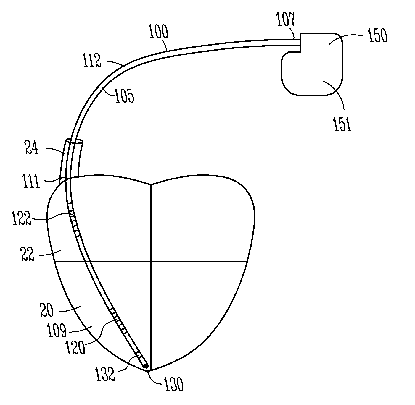
[0005] FIG. 1 shows a lead and pulse generator in accordance with one embodiment.
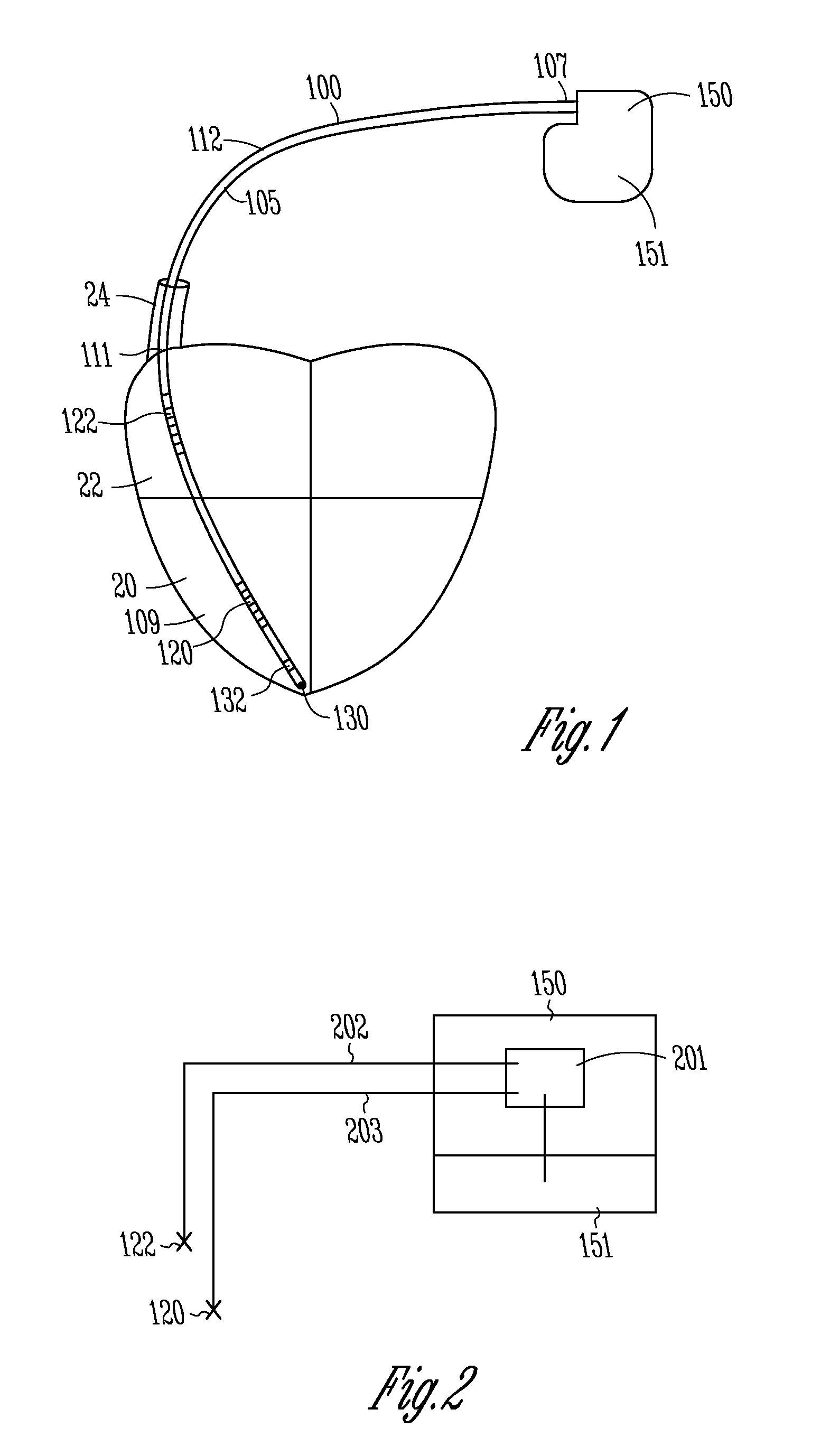
[0006] FIG. 2 shows a schematic representation of a lead and pulse generator in accordance with one embodiment.
DETAILED DESCRIPTION
[0007] In the following detailed description, reference is made to the accompanying drawings which form a part hereof, and in which is shown by way of illustration specific embodiments in which the invention may be practiced. These embodiments are described in sufficient detail to enable those skilled in the art to practice the invention, and it is to be understood that other embodiments may be utilized and that structural changes may be made without departing from the scope of the present invention. Therefore, the following detailed description is not to be taken in a limiting sense, and the scope of the present invention is defined by the appended claims and their equivalents.
[0008] FIG. 1 shows a view of a lead 100 coupled to a pulse generator 150. In one embodiment, lead 100 is adapted to deliver defibrillation shock energy to a heart. Certain embodiments deliver pacing pulses to a heart. Pulse generator 150 can be implanted in a surgically-formed pocket in a patient's chest or other desired location. Pulse generator 150 generally includes electronic components to perform signal analysis, processing, and control. Pulse generator 150 can include a power supply such as a battery, a capacitor, and other components housed in a case or can 151. The device can include microprocessors to provide processing and evaluation to determine and deliver electrical shocks and pulses of different energy levels and timing for ventricular defibrillation, cardioversion, and pacing to a heart in response to cardiac arrhythmia including fibrillation, tachycardia, and bradycardia.
[0009] In one embodiment, lead 100 includes a lead body 105 extending from a proximal end 107 to a distal end 109 and having an intermediate portion 111. Lead 100 includes one or more conductors, such as coiled conductors or other conductors, to conduct energy from pulse generator 150 to one or more electrodes, such as a distal defibrillation coil electrode 120 configured to be implanted in right ventricle 20, and a proximal defibrillation coil electrode 122 configured to be implanted in right atrium 22 or superior vena cava 24. The superior vena cava and the right atrium are called the supraventricular portion of the heart. In one embodiment, the lead 100 can include a tip electrode 130 and a distal ring electrode 132 for ventricular sensing and pacing. Some embodiments include one or more proximal ring electrodes for atrial sensing and pacing.
[0010] Lead 100 can include lead terminal pins which are attached to pulse generator 150 at a header. The system can include a unipolar system with the housing can 151 acting as an electrode or a bipolar system with a pulse between two electrodes 120, 122, or electrodes 130, 132.
[0011] The present system is directed to providing a supraventricular tachycardia sensing vector. The present system provides a technique to better distinguish supraventricular tachycardia (SVT) from ventricular tachycardia (VT). For example, in a past approach, the proximal coil 122 was electrically coupled to can electrode 151 and tachycardia sensing was performed using the distal coil 120 to both the can 151 plus the proximal coil 122. However, this configuration results in difficulties in distinguishing between SVT and VT.
[0012] In one embodiment, the present system electrically isolates the can electrode 151 from proximal coil electrode 122 and from the distal coil electrode 120 to provide a supraventricular tachy sensing vector. For example, coil electrode 122 can be electrically isolated from the can electrode 151 and a unipolar sensing vector can be from the proximal coil electrode 122 to the can electrode 151. In one embodiment, a unipolar sensing vector can be from the distal coil 120 to the can electrode 151. In one embodiment, a sensing vector can be from distal coil 120 to proximal electrode 122. These configurations are useful for distinguishing between SVT and VT.
[0013] In other embodiments, the present system uncouples the proximal electrode 122 from the can 151 and provides sensing utilizing one or more of electrodes 130, 132.
[0014] The term sensing vector is described herein by the location of the two electrodes used by a sensing channel within the pulse generator. The sensing channel uses the electrical signal that exists between the two electrodes to sense cardiac activity. Different sense vectors will present different aspects of the cardiac signal to the sensing channel. In the present embodiments, the sense vectors have improved performance for sensing SVT because these vectors produce a larger SVT to VT signal ratio than in the past.
[0015] Thus in various examples, both of the coil electrodes 120, 122 are electrically uncoupled from the can electrode 151 such that a unipolar sensing vector is provided between at least one of the coil electrodes and the can electrode 151. For example, the sensing vector can be provided between the distal electrode 120 and the can electrode 151, or the sensing vector can be provided between the proximal electrode 122 and the can electrode 151. In another example a second sensing vector can be provided between the distal coil electrode 120 and the proximal coil electrode 122.
[0016] In another example, the pulse generator can be configured such that the unipolar sensing vector can alternate between the distal coil electrode 120 and the can electrode 151 and the proximal electrode 122 and the can electrode 151. In one embodiment, the pulse generator is configured such that a first unipolar sensing vector between the distal coil electrode 120 and the can electrode 151 and a second unipolar sensing vector between the proximal electrode 122 and the can electrode 151 occur simultaneously.
[0017] The pulse generator can be configured to distinguish between VT and SVT using the unipolar sensing vectors discussed above. For example, one technique to distinguish between VT and SVT is to use a template of the correlation between shock vector electrograms and RV rate vector electrograms during normal sinus rhythm. When an arrhythmia is detected, the template is compared to the on-going rhythm; if the rhythm matches the existing template, then it is believed that the origin of the rhythm is supraventricular and the device withholds therapy--the assumption being that a supraventricular rhythm follows the same conduction pathway as normal sinus rhythm, and thus the correlation of the two vectors during SVT would match the normal sinus rhythm template, and therapy can be delivered.
[0018] However, if the correlation of the vectors during the rhythm does not match the template, then it is assumed that the rhythm is VT (i.e. the rhythm is not using the normal conduction pathway).
[0019] Further embodiments can use a different template created from the new vectors described herein. This new template would provide more power to discriminate problem cases using the template described above--and thus more information from the combination of more vectors would yield more discrimination power.
[0020] In one embodiment, electrode 122 is disposed along the lead such that the electrode 122 is configured to be located in the right atrium 22 or superior vena cava 24 after implantation.
[0021] FIG. 2 shows a schematic representation of portions of the system described above, in accordance with one embodiment. The lead includes a first conductor 202 coupled between the coil electrode 122 and electronics 201 within the pulse generator 150. The lead also includes a second conductor 203 coupled between distal coil electrode 120 and electronics 201. The can electrode 151 is also coupled to the electronics 201. Electronics 201 includes electrically pathways which provide that the electrodes 122, and 120 are electrically insulated from the can electrode 151. As discussed, the electronics 201 can be configured to allow the various connections to be uncoupled or coupled as desired.
[0022] It is understood that the above description is intended to be illustrative, and not restrictive. Many other embodiments will be apparent to those of skill in the art upon reviewing the above description. The scope of the invention should, therefore, be determined with reference to the appended claims, along with the full scope of equivalents to which such claims are entitled.
* * * * *
D00000
D00001
XML
uspto.report is an independent third-party trademark research tool that is not affiliated, endorsed, or sponsored by the United States Patent and Trademark Office (USPTO) or any other governmental organization. The information provided by uspto.report is based on publicly available data at the time of writing and is intended for informational purposes only.
While we strive to provide accurate and up-to-date information, we do not guarantee the accuracy, completeness, reliability, or suitability of the information displayed on this site. The use of this site is at your own risk. Any reliance you place on such information is therefore strictly at your own risk.
All official trademark data, including owner information, should be verified by visiting the official USPTO website at www.uspto.gov. This site is not intended to replace professional legal advice and should not be used as a substitute for consulting with a legal professional who is knowledgeable about trademark law.