Skin Patches For Sensing Or Affecting A Body Parameter
DEARDEN; BRIAN R. ; et al.
U.S. patent application number 16/362459 was filed with the patent office on 2019-09-26 for skin patches for sensing or affecting a body parameter. This patent application is currently assigned to THE ALFRED E. MANN FOUNDATION FOR SCIENTIFIC RESEA RCH. The applicant listed for this patent is THE ALFRED E. MANN FOUNDATION FOR SCIENTIFIC RESEARCH. Invention is credited to BRIAN R. DEARDEN, JOHN G. PETROVICH.
| Application Number | 20190290455 16/362459 |
| Document ID | / |
| Family ID | 67984472 |
| Filed Date | 2019-09-26 |


| United States Patent Application | 20190290455 |
| Kind Code | A1 |
| DEARDEN; BRIAN R. ; et al. | September 26, 2019 |
SKIN PATCHES FOR SENSING OR AFFECTING A BODY PARAMETER
Abstract
Skin patch sensors for monitoring and/or affecting body parameters, with alignment, positioning and attachment using magnets. The repeated use of releasable adhesive layers to retain skin patch sensors on skin can cause skin irritation, which can be reduced by rotating a skin patch between attachment times around a magnetically coupled pivot point. Skin patch sensors can be configured with internal coils to inductively couple to external power transmitting and communications coils with solenoids in anti-Helmholtz configurations.
| Inventors: | DEARDEN; BRIAN R.; (PASADENA, CA) ; PETROVICH; JOHN G.; (VALLEY VILLAGE, CA) | ||||||||||
| Applicant: |
|
||||||||||
|---|---|---|---|---|---|---|---|---|---|---|---|
| Assignee: | THE ALFRED E. MANN FOUNDATION FOR
SCIENTIFIC RESEA RCH VALENCIA CA |
||||||||||
| Family ID: | 67984472 | ||||||||||
| Appl. No.: | 16/362459 | ||||||||||
| Filed: | March 22, 2019 |
Related U.S. Patent Documents
| Application Number | Filing Date | Patent Number | ||
|---|---|---|---|---|
| 62647129 | Mar 23, 2018 | |||
| Current U.S. Class: | 1/1 |
| Current CPC Class: | A61F 2002/707 20130101; A61B 2560/0412 20130101; A61F 2/72 20130101; A61B 5/0492 20130101; A61B 5/0002 20130101; A61B 5/6833 20130101; B25J 9/0006 20130101 |
| International Class: | A61F 2/72 20060101 A61F002/72; A61B 5/0492 20060101 A61B005/0492; B25J 9/00 20060101 B25J009/00; A61B 5/00 20060101 A61B005/00 |
Claims
1. A skin patch for releasable attachment to a skin location comprising: a sensor for sensing a body parameter and/or a transducer for affecting a body parameter; a communications system coupled to the sensor and/or the transducer; and an antenna coupled to the communications system for receiving wireless power transmissions for powering the skin patch; wherein the antenna comprises a coil configured to inductively couple with an external plurality of solenoids in an anti-Helmholtz configuration, the antenna providing at least one of the following: transmitting a wireless data signal corresponding to the sensed body parameter; and/or receiving wireless commands to affect the body parameter from an external controller.
2. The skin patch of claim 1, wherein the antenna comprises at least one of: a spiral coil configured to inductively couple to the external plurality of solenoids in an anti-Helmholtz configuration; or a solenoid configured to inductively couple to the external plurality of solenoids in an anti-Helmholtz configuration.
3. The skin patch of claim 1, further comprising a substrate for releasably attaching the skin patch to the skin location, the substrate having first and second opposite facing surfaces, and the substrate comprises: an adhesive coating on the first layer of the substrate for releasable attachment to the skin patch; and an adhesive coating on the second layer of the substrate for releasable attachment to the skin location.
4. The skin patch of claim 1, further comprising: at least one implantable ferromagnetic element configured for subcutaneous implantation below the skin location; and at least one magnet in the skin patch for supercutaneous positioning in proximity to and for magnetic coupling with the at least one implantable ferromagnetic element; and optionally the at least one implantable ferromagnetic element comprises a magnet.
5. The skin patch of claim 4, wherein the at least one implantable ferromagnetic element is a pivot point for the rotation of the skin patch.
6. A system for controlling a prosthetic limb or an exoskeleton comprising: the skin patch according to claim 1, wherein the skin patch further comprises a plurality of electrodes for sensing electromyographic (EMG) signals in a residual limb or a limb coupled to an exoskeleton, wherein the plurality of electrodes are coupled to a transmitter, and the transmitter is configured to transmit a data signal corresponding to the sensed EMG signals via the antenna; optionally at least one of the plurality of electrodes comprises at least one of: a needle electrode or a silicon electrode; and a controller configured for coupling to the residual limb or to the limb coupled to an exoskeleton, comprising: an antenna for receiving the data signal from the skin patch; and the antenna transmits wireless power to the skin patch; a receiver coupled to the antenna for processing the received data signal; a transmitter coupled to the antenna for communications with the skin patch; and the controller coupled to the receiver for generating a plurality of motion control commands for the prosthetic limb or the exoskeleton; the prosthetic limb or the exoskeleton coupled to the controller and configured to receive and respond to the motion control commands.
7. The system of claim 6, wherein the antenna of the controller comprises a plurality of solenoids in an anti-Helmholtz configuration for inductively coupling alternating current to the skin patch.
8. A skin patch for multiple releasable attachments to a skin location comprising: a sensor for sensing a body parameter and/or a transducer for affecting a body parameter; a communications system coupled to the sensor and/or transducer; an antenna coupled to the communications system for providing at least one of the following: transmitting a wireless data signal corresponding to the sensed body parameter; and/or receiving commands from an external controller; and/or a power supply for powering the skin patch; at least one magnet configured to be positioned in the skin patch above an alignment area within the skin location; and at least one implantable ferromagnetic element configured for subcutaneous implantation below the alignment area within the skin location and for magnetic coupling with the magnet; and optionally the at least one implantable electromagnetic element comprises a magnet.
9. The skin patch of claim 8, wherein the magnetic coupling between the at least one magnet and the at least one implantable electromagnetic element releasably attach the skin patch to the skin location.
10. The skin patch of claim 8, wherein the magnetic coupling between the at least one magnet and the at least one implantable electromagnetic element provide a pivot point for rotating the skin patch prior to a subsequent releasable attachment of the skin patch to the skin location.
11. The skin patch of claim 8, wherein the power supply of the skin patch consists of either: a primary battery or a rechargeable battery.
12. The skin patch of claim 8, wherein the antenna is configured to receive wireless power, and comprises at least one of: a spiral coil, a solenoid, a spiral coil configured to inductively couple to a plurality of solenoids in an anti-Helmholtz configuration or a solenoid configured to inductively couple to a plurality of solenoids in an anti-Helmholtz configuration.
13. A method for multiple releasable attachments of a skin patch to a skin location, comprising: Implanting subcutaneously a ferromagnetic element at a skin location; and optionally the implantable ferromagnetic element is a magnet; providing a skin patch for sensing and/or affecting a body parameter, the skin patch comprising a magnet configured to align and magnetically couple to the implanted element; attaching a first substrate to the skin patch; wherein the first substrate has first and second opposite facing surfaces, the first substrate comprising: an adhesive coating on the first layer of the first substrate for releasable attachment to the skin patch; and an adhesive coating on the second layer of the first substrate for releasable attachment to the skin location; positioning the skin patch at the skin location with alignment and magnetic coupling between the magnet and the implanted ferromagnetic element; attaching the skin patch to the skin location using the first substrate; sensing a body parameter and/or affecting a body parameter; detaching the skin patch from the skin location; detaching the first substrate from the skin patch; attaching a second substrate to the skin patch; wherein the second substrate has first and second opposite facing surfaces, the second substrate comprising: an adhesive coating on the first layer of the second substrate for releasable attachment to the skin patch; and an adhesive coating on the second layer of the second substrate for releasable attachment to the skin location; positioning the skin patch at the skin location with alignment and magnetic coupling between the magnet and the implanted ferromagnetic element; rotating the skin patch using the implanted ferromagnetic element as a pivot point; and attaching the skin patch to the skin location using the second substrate.
14. The method of claim 13, wherein the location of the magnet in the skin patch is offset from the center of the skin patch.
15. The method of claim 13, wherein the rotating the skin patch using the implanted ferromagnetic element as a pivot point, configures the skin patch to releasably attach to the skin location and reduces the area size of repeated skin adhesions by the skin patch.
16. A wireless power transfer system comprising: a wireless power transmitting system comprising: a coil driver generating an alternating current; first and second solenoids coupled to the coil driver in an anti-Helmholtz configuration; a wireless power receiving system positioned adjacent to the first and second solenoids, comprising: a coil configured for inductive coupling to the first and second solenoids for receiving wireless power transmissions; a power supply coupled to the coil; and electronic systems coupled to and powered by the power supply.
17. The wireless power system of claim 16, wherein the coil of the wireless power receiving system comprises at least one of: a spiral coil configured to inductively couple to the first and second solenoid of the wireless power transmitting system; or a solenoid configured to inductively couple to the first and second solenoid of the wireless power transmitting system.
18. The wireless power system of claim 16, wherein the wireless power receiving system further comprises: skin patch for releasable attachment to a skin location, comprising: a sensor for sensing a body parameter and/or a transducer for affecting a body parameter; a communications system coupled to the sensor and/or the transducer; the coil is coupled to the communications system, providing at least one of the following: transmitting a wireless data signal corresponding to the sensed body parameter to the wireless power transmitting system; and/or receiving wireless commands to affect the body parameter from the wireless power transmitting system.
19. The wireless power system of claim 18, wherein the wireless power receiving system further comprises a substrate for releasably attaching the skin patch to the skin location, the substrate having first and second opposite facing surfaces, and the substrate comprises: an adhesive coating on the first layer of the substrate for releasable attachment to the skin patch; and an adhesive coating on the second layer of the substrate for releasable attachment to the skin location.
20. The wireless power system of claim 18, wherein the wireless power receiving system further comprises: at least one implantable ferromagnetic element configured for subcutaneous implantation below the skin location; and at least one magnet in the skin patch for supercutaneous positioning in proximity to and for magnetic coupling with the at least one implantable ferromagnetic element; and optionally the at least one implantable ferromagnetic element comprises a magnet; and optionally the at least one implantable ferromagnetic element is a pivot point for the rotation of the skin patch.
21. The wireless power system of claim 18, wherein the wireless power receiving system further comprises: a plurality of electrodes coupled to the skin patch, the plurality of electrodes sense electromyographic (EMG) signals in a residual limb or a limb coupled to an exoskeleton; and a transmitter coupled to the plurality of electrodes, and the transmitter is configured to transmit a data signal corresponding to the sensed EMG signals via the coil; optionally at least one of the plurality of electrodes comprises at least one of: a needle electrode or a silicon electrode.
22. The wireless power system of claim 21, wherein the wireless power transmitting system further comprises: a controller configured for coupling to the residual limb or to the limb coupled to an exoskeleton, comprising: the first and second solenoids receive the data signal from the skin patch; a receiver coupled to the first and second solenoids for processing the received data signal; a transmitter coupled to the first and second solenoids for communications with the skin patch; and the controller coupled to the receiver for generating a plurality of motion control commands for the prosthetic limb or the exoskeleton; the prosthetic limb or the exoskeleton coupled to the controller and configured to receive and respond to the motion control commands.
Description
CROSS REFERENCE TO RELATED APPLICATIONS
[0001] The present application claims benefit under 35 U.S.C. .sctn. 119(e) to U.S. Provisional Application Ser. No. 62/647,129, filed on Mar. 23, 2018 which is incorporated herein by reference in its entirety.
BACKGROUND
[0002] It is estimated that there are over 1 million people in the United States with limb loss. Various prosthetic devices have been developed to assist persons with such limb loss. Commercial systems available to date have relied on surface electromyographic (EMG) sensors with limited success, due to the difficulty of obtaining reliable muscle activity data from surface EMG sensors. Recent clinical trials of a system developed by The Alfred E, Mann Foundation For Scientific Research have shown the many advantages of an Implantable Myoelectric Sensor System (IMES.TM.) using implanted myoelectric sensors. See Pasquina, P. F., et al, First-in-Man Demonstration of Fully Implanted Myoelectric Sensors for Control of an Advanced Electromechanical Arm by Transradial Amputees, Journal of Neuroscience Methods, 2015, Apr. 15, 244: 85-93 and Merrill, D. R., et al, Development of an Implantable Myoelectric Sensor for Advanced Prosthesis Control, Artificial Organs, 2011, Mar., 35(3): 249-252.
[0003] Surface EMG sensors for prosthetic control are less expensive than implantable EMG sensors and may be more practical for the control of prosthetics as pattern recognition software is developed to interpret the multiple surface EMG signals received in order to properly move the prosthetic limb. EMG sensors can be used in medical systems for various applications, such as for example, measuring parasternal EMG signals in patients with chronic obstructive pulmonary disease (COPD) in order to determine their neural respiratory drive (NRD). See for example, US patent application publication 2013/0310699. Improved surface EMG sensors and systems would also enable the development and use of powered exoskeletons for therapy and rehabilitation of patients with mobility impairing ailments such as Parkinson's, multiple sclerosis, stroke and other medical conditions. See for example US patent application publications 2015/0134080 and 2017/0007489. Improved surface EMG sensors could also be useful for the control of strength enhancing exoskeletons for use in military and industrial applications.
SUMMARY
[0004] Skin patch sensors for monitoring and/or affecting body parameters, with alignment, positioning and attachment using magnets. The repeated use of releasable adhesive layers to retain skin patch sensors on skin can cause skin irritation, which can be reduced by rotating a skin patch between attachment times around a magnetically coupled pivot point. Skin patch sensors can be configured with internal coils to inductively couple to external power transmitting and communications coils with solenoids in anti-Helmholtz configurations.
BRIEF DESCRIPTION OF THE DRAWINGS
[0005] FIG. 1 is a cross sectional side view of a wireless skin patch for sensing or affecting a body parameter.
[0006] FIG. 2 is a top view of a wireless skin patch for sensing or affecting a body parameter.
[0007] FIG. 3 is a view of part of a system for EMG control of a prosthetic limb.
[0008] FIG. 4 is a view of a wireless skin patch sensor positioned on a patient's chest.
[0009] FIG. 5 is a top view of a skin patch with magnetic alignment features.
[0010] FIG. 6 is a cross sectional side view of a skin patch with magnetic alignment features.
[0011] FIG. 7 is a top view of a skin patch with magnetic positioning features.
[0012] FIG. 8 is a cross sectional side view of a skin patch with magnetic positioning features.
[0013] FIG. 9 is a view of several possible positions for a skin patch as it is rotated around a pivot point.
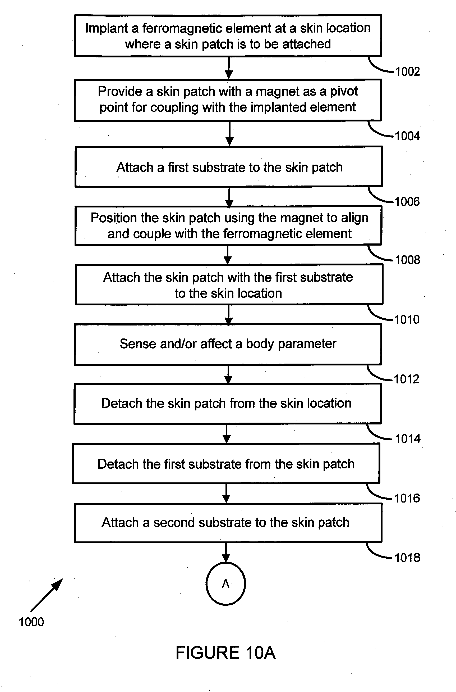
[0014] FIGS. 10A and 10B are flow charts of a method for releasably attaching a skin patch with first and second substrates with reduced skin irritation.
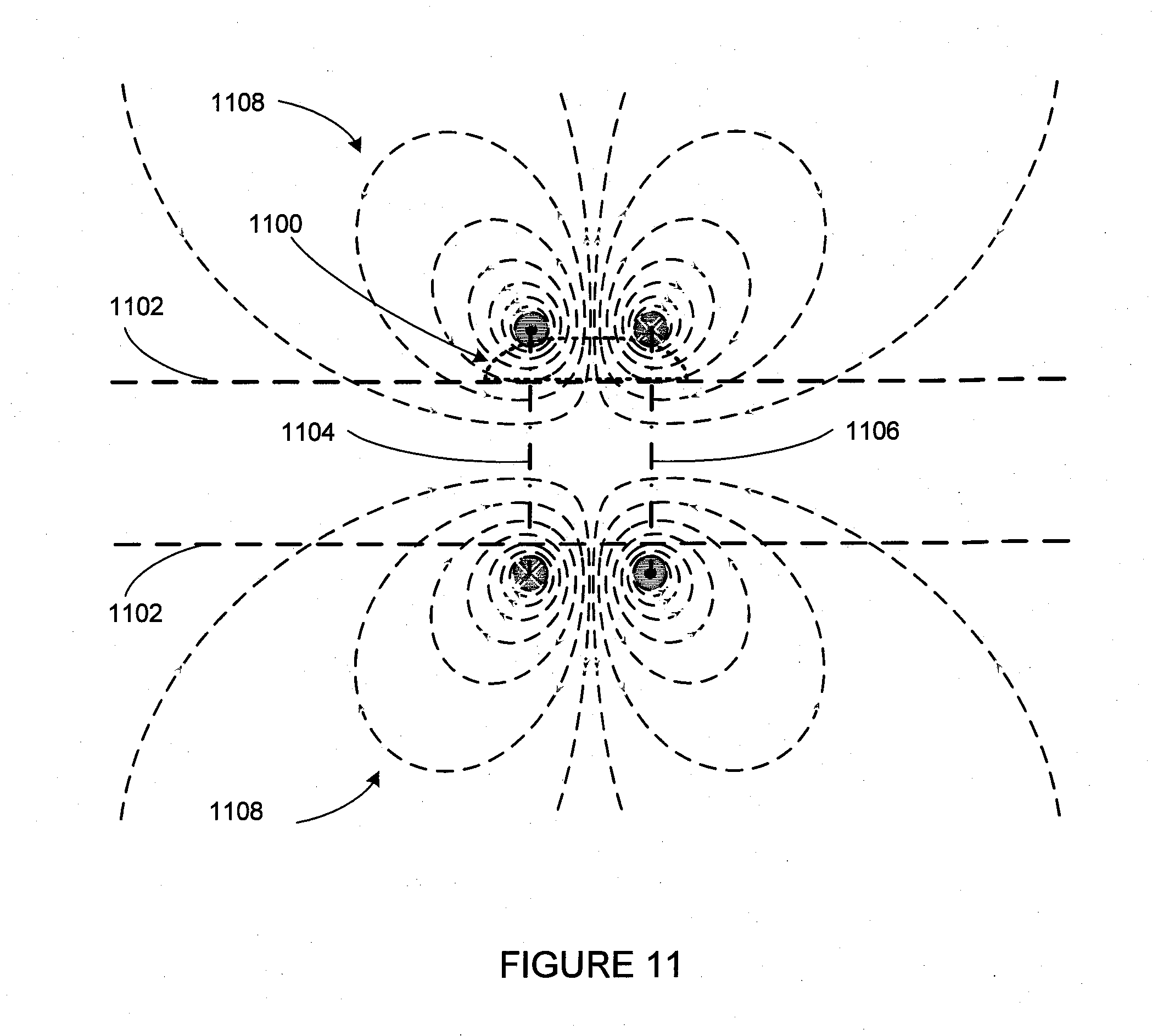
[0015] FIG. 11 is a diagram showing an outline of a limb with a skin patch wirelessly powered by a pair of solenoids in an anti-Helmholtz configuration.
[0016] FIG. 12 is a block diagram of systems in an exemplary skin patch.
[0017] FIG. 13 is a block diagram of an exemplary system for controlling a prosthesis using data signals from one or more skin patches.
DETAILED DESCRIPTION
[0018] FIG. 1 is a cross sectional side view of a wireless flexible skin patch 100 for sensing or affecting a body parameter. In some embodiments, skin patch 100 is sensing electromyographic (EMG) signals. Skin patch 100 includes electrodes 102, electronic components 104 on a flexible circuit board, flexible cover 106 and is mounted on flexible adhesive substrate 110. Electronic components 104 include one or more coils or antennas for inductively coupling the skin patch to an external power transmitting and communications coil. The electrodes may be made of stainless steel or other metal suitable for use as an electrode to which a disposable electrode may be attached, such as adhesive get type electrodes commonly used for ECG sensing. The disposable electrodes may be part of adhesive substrate 110. The electrodes could also be a micro-array made of metal or silicon that pierces the outer layers of skin in order to reduce the impedance of the interface and to improve the signal strength of the sensed electrical signals. The electrodes may also be a needle electrode, configured for injection into the skin, either subdermally for improved signal strength or deeper into a targeted muscle for selectivity and signal strength. When using needle electrodes, they could be of the bipolar type or monopolar and used in combination with a surface electrode built into adhesive substrate 110. In some embodiments, the skin patch may be configured and positioned on the skin of a person to sense other electrical signals, such as electrocardiographic (ECG) or electroencephalographic EEG signals.
[0019] In some embodiments, a skin patch 100 may incorporate other sensors such as temperature sensors, accelerometers, gyroscopes, inertial measurement units, or reflectance type blood oximetry sensors to measure blood oxygen and pulse rate. An inertial measurement unit made of a 3 axis accelerometer and a 3 axis gyroscope, when attached to skin in various chest locations on a person, can sense many parameters such as: respiration rate and strength, cardiac monitoring, patient posture and activity and fall detection.
[0020] In some embodiments, the skin patch may be configured and positioned on the skin of a person to generate transcutaneous electrical nerve stimulation (TENS) for therapeutic purposes. More than one coil can be in skin patch 100 and may have various configurations such as a planar or spiral coil, as will be discussed with regard to FIG. 2 or one or more solenoid coils, either discrete coils or part of the flex circuit, positioned for inductive coupling with an external coil providing external RF for wireless power transmission to the skin patch. A coil or coils within skin patch 100 and an external coil have to be properly oriented to each other to maximize the coupling coefficient between the coils for maximum efficiency and to maximize the immunity of the link to changes in the coupling coefficient. For example, the solenoid coils in multiple skin patches 100 in various positions around a residual limb may couple with a solenoid coil in a prosthetic socket with all of the axes of the solenoid coils substantially parallel to each other for the maximum coupling between the coils. Wireless communications with skin patch 100 may be based on a variety of methods, such as, for example, load modulation of the wireless power transmission to the skin patch 100. Such wireless communications may also include near field (NFC), Bluetooth or other communications protocols. The operating parameters of skin patch 100 may be controlled by wireless communications from a terminal controller (not shown) operated by a physician or technician or from a patient operated remote control (not shown).
[0021] The adhesive substrate 110 includes two layers of adhesive, one layer of adhesive on one side to releasably mount the substrate to the skin patch and a second layer of adhesive on the opposite side of the substrate to releasable mount the skin patch 100 to skin. Substrate 100 may be made of paper or a flexible layer of plastic for improved adhesion to curved surfaces of skin such as on an arm or a leg. In some embodiments, skin patch 100 is made with a flexible base and cover to provide the ability to be flexed upon adhesive mounting to better conform to the curvature of the limb to which it is attached, to provide a lower profile and for improved signal capture. In some embodiments, the substrate is a layer of compressible foam to provide a better fit for the skin patch to the curvature of the limb to which it is attached. In some embodiments, adhesive gel electrodes are incorporated into the adhesive substrate. In some embodiments, the skin patch is powered by a rechargeable or primary battery, where the primary battery may be changed by a user or by a technician. If the skin patch is powered by a rechargeable battery, the rechargeable battery can be charged wirelessly or through a wired connection.
[0022] FIG. 2 is a top view of a wireless skin patch 100, shown without a cover, for sensing or affecting a body parameter. Skin patch 100 includes base 108, electrodes 102, electronic components 104 and planar or spiral coil 112. Skin patch 100 may be releasably attached to skin by an adhesive substrate as discussed with regard to FIG. 1. Spiral coil 112 may be inductively coupled to an external planar coil or to a pair of solenoids in an anti-Helmholtz configuration as will be discussed with regard to FIG. 11.
[0023] FIG. 3 is a view of part of a prosthesis control system 300 for EMG control of a prosthetic limb. Residual limb 312 is coupled to system 300 and includes prosthetic socket 302 and prosthesis 310. Several skin patch EMG sensors 306 monitor multiple EMG signals in residual limb 312 and transmit EMG data signals to prosthesis control system 300. Prosthesis control system 300 includes solenoid 304 for transmitting alternating current to power EMG sensors 306 and for bidirectional communications with EMG sensors 306. Prosthetic socket 302 includes electronic systems, such as a power supply, a controller, analog and digital signal processing to receive the multiple EMG data signals from skin patches 306 to generate motion control commands, which are sent to a prosthesis controller. The prosthesis controller is connected to and actuates the motion of prosthesis 310. The operating parameters of prosthesis control system 300 may be controlled by wireless communications from a terminal controller (not shown) operated by a physician or technician or from a patient operated remote control (not shown). The electronic systems of the prosthesis system 300 are discussed with respect to FIG. 11.
[0024] FIG. 4 is a view of a wireless skin patch 400 positioned on a patient's chest 402. As was described with respect to skin patch 100, skin patch 400 may be any one of a variety of sensors such as EMG, ECG or a motion sensor using an inertial measuring unit.
[0025] FIG. 5 is a top view of a skin patch 500 with magnetic alignment features. Skin patch 500 includes base 502, circular magnet 504 and optional longitudinal magnets 506. The arrows 508 indicate that skin patch 500 may be rotated around the pivot point defined by implanted element 510 in between repeated attachments of skin patch 500 to the same general skin location. Other aspects of skin patch 500, such as the electronic components and coil are not shown to simplify this figure. Circular element 510 is a ferromagnetic element for implantation below the skin as an alignment point for repeated positioning of skin patch 500 to the same location on skin. After element 510 is implanted below the skin, skin patch 500 is positioned in proximity to element 510 and magnet 504 magnetically couples to element 510 and skin patch 500 can be attached to that section of skin where element 510 is located, using an adhesive substrate, such as was described with respect to FIG. 1. In some embodiments, element 510 is a magnet and is oriented such that after implantation, it magnetically couples to magnet 504 at the time of the attachment of skin patch 500 to the skin location defined by the implanted element 510. In some embodiments, skin patch 500 includes additional magnets 506 which can also be used for the alignment of skin patch 500 to a skin location using implanted magnets 602 as shown in FIG. 6.
[0026] After skin patch 500 has been attached at a skin location and is later detached from the skin location, a new adhesive substrate can be attached to skin patch 500. Then skin patch 500 can be positioned above implanted element 510 using the magnetic coupling between magnet 504 and implant 510 to align skin patch 500 with the skin location and skin patch 500 can be rotated as indicated by arrows 508 about a pivot point defined by implant 510. This can reduce the amount of skin used for such repeated attaching of skin patch 500 and thus reduce skin irritation.
[0027] FIG. 6 is a cross sectional side view of skin patch 600 retained on skin 604 with magnetic alignment features. Skin patch 500 includes base 502, circular magnet 504 and optional longitudinal magnets 506. Shown implanted below the skin 604 are element 510 and optional ferromagnetic elements 602, which in some embodiments are magnets. Magnets 504 and 506 are used for alignment with elements 510 and 602 and skin patch 500 can be held in position on the skin using an adhesive substrate. In some embodiments, elements 510 and 602 are magnets and the magnetic coupling and the attractive forces between the magnets 504 and 506 above the skin, and the magnets 510 and 602 below the skin, can be sufficient to keep skin patch 500 in position on the skin, even if no adhesive substrate is used to retain skin patch 500 on the skin. The central aperture in magnet 504 can be used to provide an opening for one or more electrodes in some embodiments.
[0028] FIG. 7 is a top view of skin patch 700 with magnetic positioning features. Skin patch 700 includes base 702 and longitudinal magnets 706 and is similar to skin patch 500 in FIG. 5, except that there is no central magnet 504, which provides more space for various sensors in the center of skin patch 700. Elements 710 are ferromagnetic elements for implantation below the skin as alignment points for repeated positioning of skin patch 700 to the same location on skin. In some embodiments, elements 710 are magnets.
[0029] FIG. 8 is a cross sectional side view of skin patch 800 retained on skin 802 with magnetic positioning features. Skin patch 700 includes base 702 and longitudinal magnets 704. Shown implanted below the skin 802 are ferromagnetic elements 710, which in some embodiments can be magnets. Magnets 704 are used for alignment with elements 710 and skin patch 700 can be held in position on the skin using an adhesive substrate. In some embodiments, elements 710 are also magnets and the attractive forces between the magnets 704 above the skin, and the magnets 710 below the skin, can be sufficient to keep skin patch 700 in position on the skin, even if no adhesive substrate is used to retain skin patch 700 on the skin.
[0030] FIG. 9 is a view of several possible positions for skin patch 900 as it is rotated, around a pivot point defined by magnet 902 offset from the center of the skin patch, and an implanted ferromagnetic element just below the position of magnet 902, which is not shown in FIG. 9. For example, skin patch 900 can be in position 900A for an adhesive attachment to the skin location underneath and after skin patch 900 is detached from the skin, it can be reattached via rotation as indicated by arrows 904 at location 900B or 900C or any other position that can be reached by rotation around a pivot point defined by the magnetic coupling of magnet 902 to an implanted ferromagnetic element below magnet 902. Such rotation between attachments to the same general skin location will reduce the amount of skin exposed to adhesives and thus reduce the area size of any resultant skin irritation. Magnet 902 may have any of a variety of polygon type shapes and be configured with or without a central aperture.
[0031] FIGS. 10A-10B illustrate a flow chart of a method 1000 for releasably attaching a skin patch with first and second substrates to the same general skin location at different times. Exemplary method 1000 can apply to the skin patches shown in FIGS. 5-9. In block 1002, a ferromagnetic element is implanted subcutaneously at a skin location. In block 1004, a skin patch is provided for sensing and/or affecting a body parameter. The skin patch has a magnet configured to align with and magnetically couple to the implanted element. In block 1006, a first substrate is attached to the bottom of the skin patch. The first substrate has a first surface with an adhesive coating for releasable attachment to the bottom surface of the skin patch. The first substrate has a second surface with an adhesive coating on the second layer of the first substrate for releasable attachment to the skin location. In block 1008, the skin patch is positioned at the skin location with the implanted ferromagnetic element in alignment with the magnet and with magnetic coupling between the magnet and the implanted ferromagnetic element.
[0032] In block 1010, the skin patch is attached to the skin location with the first substrate. In block 1012, the skin patch is used to sense or affect a body parameter. In block 1014, the skin patch is detached from the skin location. In block 1016, the first substrate is detached from the skin patch. In block 1018, a second substrate is attached to the skin patch. The second substrate has a first surface with an adhesive coating for releasable attachment to the bottom surface of the skin patch. The second substrate has a second surface with an adhesive coating on the second layer of the second substrate for releasable attachment to the skin location.
[0033] In block 1020, the skin patch is positioned at the skin location with the implanted ferromagnetic element in alignment with the magnet and with magnetic coupling between the magnet and the implanted ferromagnetic element. In block 1022, the skin patch is rotated using the implanted ferromagnetic element as a pivot point. This reduces the amount of skin being reattached to each time and results in a smaller area of irritated skin. In block 1024, the skin patch is attached to the skin location using the second substrate. In block 1026, the skin patch is used to sense or affect a body parameter. This process 1000 can be repeated as needed by repeating steps 1014 to 1026 with subsequent adhesive substrates and rotating the skin patch as needed each time before reattaching the skin patch to the same general skin location to reduce the area of irritated skin.
[0034] FIG. 11 is a diagram showing the outline of skin patch 1100 mounted on limb 1102 and wirelessly powered by a pair of solenoids 1104 and 1106 in an anti-Helmholtz configuration. In an anti-Helmholtz configuration, two solenoids are positioned along the same axis with the current flow in each solenoid being opposite to the current flow in the other solenoid. The distance between the solenoids is equal to the radius of the solenoids. In the center of the space between the solenoids, the magnetic field is zero, but the magnetic field is not zero away from the center and varies as is shown by the approximate field lines 1108. Skin patch 1100 has an internal planar or spiral coil, similar to coil 112 in FIG. 2, and this internal spiral coil is inductively coupled to the non-zero magnetic field generated by the solenoid coils 1104 and 1106 near to the surface of limb 1102. An anti-Helmholz solenoid configuration can wirelessly power a number of skin patches 1100 positioned on the surface of a limb 1102. In some embodiments, skin patch 1100 has an internal solenoid oriented for inductive coupling for power transfer from external solenoids in an anti-Helmholtz configuration.
[0035] FIG. 12 is a block diagram of systems in an exemplary skin patch 1200 for EMG sensing. Skin patch 1200 can be similar to the skin patches described with respect to FIGS. 1-3 and 4-9. Skin patch 1200 is positioned on a skin location and senses EMG signals from muscle 1202 through skin 1216 using electrodes 1204. The electrodes 1204 are connected to an analog signal processing system 1206, which is connected to an analog to digital converter (ADC) 1208. The output of ADC 1208 is modulated by modulator 1210, the output of which is connected to skin patch coil 1212. Coil 1212 operates as an antenna to transmit the processed EMG signals to a prosthesis control system, such as described with regard to FIGS. 3 and 13, or in some embodiments, to an exoskeleton control system. In some embodiments, coil 1212 receives RF power signals which are coupled to power supply 1214 for powering skin patch 1200 and for recharging a rechargeable battery. Controller 1216 generates command signals to the various systems in skin patch 1200. Controller 1216 may be a microcontroller, a microprocessor, or a state machine. Power supply 1214 may include a primary or rechargeable battery.
[0036] FIG. 13 is a block diagram of an exemplary prosthesis control system 1300 for controlling a prosthesis or an exoskeleton using EMG data signals from one or more skin patches, for example, as was described with respect to FIG. 3 and FIG. 12. Socket coil 1302 may be wirelessly coupled to coil 1212 of skin patch 1200 in FIG. 12 to receive EMG data signals. In some embodiments, coil 1302 is connected to power supply 1316 and transmits an RF signal to a skin patch for power transmission. Coil 1302 is connected to analog front end 1304 for demodulating the received EMG data transmission from a skin patch 1200. The demodulated output of analog front end 1304 is connected to digital signal processing 1306 for recovery of the sensed EMG data. The output of digital signal processing 1306 is connected to controller 1308, which generates motion commands to prosthesis 1310 or to an exoskeleton. Controller 1308 is connected to communications systems 1312 to provide an RF link, such as NFC, Bluetooth or other communications protocol to external devices such as a clinician programmer 1314 or a remote control (not shown). In one embodiment, a control system similar to prosthesis control system 1300 may control an exoskeleton using several skin patches 100.
* * * * *
D00000
D00001
D00002
D00003
D00004
D00005
D00006
D00007
D00008
D00009
D00010
XML
uspto.report is an independent third-party trademark research tool that is not affiliated, endorsed, or sponsored by the United States Patent and Trademark Office (USPTO) or any other governmental organization. The information provided by uspto.report is based on publicly available data at the time of writing and is intended for informational purposes only.
While we strive to provide accurate and up-to-date information, we do not guarantee the accuracy, completeness, reliability, or suitability of the information displayed on this site. The use of this site is at your own risk. Any reliance you place on such information is therefore strictly at your own risk.
All official trademark data, including owner information, should be verified by visiting the official USPTO website at www.uspto.gov. This site is not intended to replace professional legal advice and should not be used as a substitute for consulting with a legal professional who is knowledgeable about trademark law.