Mpi Method And System For Visually Representing Mpi Image Data
FRANKE; Jochen ; et al.
U.S. patent application number 16/351743 was filed with the patent office on 2019-09-19 for mpi method and system for visually representing mpi image data. The applicant listed for this patent is Bruker BioSpin MRI GmbH. Invention is credited to Jochen FRANKE, Michael HERBST.
| Application Number | 20190285710 16/351743 |
| Document ID | / |
| Family ID | 65235360 |
| Filed Date | 2019-09-19 |


| United States Patent Application | 20190285710 |
| Kind Code | A1 |
| FRANKE; Jochen ; et al. | September 19, 2019 |
MPI METHOD AND SYSTEM FOR VISUALLY REPRESENTING MPI IMAGE DATA
Abstract
A method for establishing a local concentration distribution of magnetic particles of at least one particle class within an examination volume or a variable derived from this concentration distribution. The method includes providing at least one system matrix, providing MPI signal data of at least one sample including magnetic particles of at least one particle class within a measurement volume, and reconstructing spatially resolved MPI image data from the provided MPI signal data. At least one spatial projection of at least one part of the system matrix is carried out along a projection direction and a projected system matrix is generated thereby. The reconstruction of the MPI image data is implemented with the at least partly projected system matrix, as a result of which MPI image data of a spatial projection of the local concentration distribution of the magnetic particles are produced along the projection direction.
| Inventors: | FRANKE; Jochen; (Karlsruhe, DE) ; HERBST; Michael; (Freiburg, DE) | ||||||||||
| Applicant: |
|
||||||||||
|---|---|---|---|---|---|---|---|---|---|---|---|
| Family ID: | 65235360 | ||||||||||
| Appl. No.: | 16/351743 | ||||||||||
| Filed: | March 13, 2019 |
| Current U.S. Class: | 1/1 |
| Current CPC Class: | A61B 5/0515 20130101; G01R 33/1276 20130101; A61B 5/05 20130101; A61B 90/00 20160201; G16H 30/20 20180101; G16H 30/40 20180101; G06F 17/16 20130101; G01R 33/00 20130101 |
| International Class: | G01R 33/12 20060101 G01R033/12; G06F 17/16 20060101 G06F017/16 |
Foreign Application Data
| Date | Code | Application Number |
|---|---|---|
| Mar 13, 2018 | DE | 10 2018 203 783.3 |
Claims
1. A method for establishing a local concentration distribution of magnetic particles of at least one particle class within an examination volume or a variable derived from this concentration distribution, comprising: providing at least one system matrix; providing magnetic particle imaging (MPI) signal data of at least one sample comprising magnetic particles of at least one particle class within a measurement volume; performing at least one spatial projection of at least one part of the system matrix along a projection direction, to generate a projected system matrix; reconstructing spatially resolved MPI image data from the provided MPI signal data; wherein the reconstructing of the MPI image data is implemented with the at least partly projected system matrix, whereby the MPI image data of a spatial projection of the local concentration distribution of the magnetic particles or of the variable derived from this concentration distribution are produced along the projection direction.
2. The method as claimed in claim 1, further comprising performing further spatial projections in different projection directions.
3. The method as claimed in claim 1, further comprising varying the projection direction during the MPI measurement.
4. The method as claimed in claim 1, wherein only selected frequency components of the system matrix are used for the projection and/or the reconstruction.
5. The method as claimed in claim 4, wherein the selected frequency components of the system matrix used for the reconstruction are only those whose signal-to-noise ratio lies above a threshold value.
6. The method as claimed in claim 1, wherein only MPI image data from selected regions of the examination volume are used for the reconstruction.
7. The method as claimed in claim 1, wherein the reconstruction is implemented in a sparse domain.
8. The method as claimed in claim 1, wherein the system matrix is measured with an MPI calibration measurement.
9. The method as claimed in claim 1, wherein the system matrix is simulated.
10. The method as claimed in claim 1, wherein the provided system matrix is generated from at least two system matrices linked by a mathematical operation.
11. The method as claimed in claim 1, wherein providing the at least one system matrix comprises establishing at least two system matrices and generating respectively one projected system matrix for the system matrices, wherein the spatial projections of the system matrices are implemented along same projection directions, wherein the method further comprises appending the projected system matrices, and wherein the MPI image data are reconstructed with the projected and appended system matrix.
12. A system for visually representing MPI image data of a spatial projection of a local concentration distribution of magnetic particles or a spatial projection of a variable derived from this concentration distribution in a projection direction, comprising: i) an MPI installation configured to detect MPI signal data, ii) an electronic storage medium containing a projected system matrix or a stored computer program configured to generate a system matrix projected along a projection direction, iii) a stored computer program, configured to reconstruct the MPI image data with the projected system matrix, and iv) an indicator apparatus configured to display the reconstructed MPI image data in real-time.
13. The system as claimed in claim 12, configured to perform a method for establishing a local concentration distribution of magnetic particles of at least one particle class within an examination volume or a variable derived from this concentration distribution, comprising: providing at least one system matrix; providing MPI signal data of at least one sample comprising magnetic particles of at least one particle class within a measurement volume; performing at least one spatial projection of at least one part of the system matrix along a projection direction, to generate a projected system matrix; and reconstructing spatially resolved MPI image data from the provided MPI signal data; wherein the reconstructing of the MPI image data is implemented with the at least partly projected system matrix, whereby the MPI image data of a spatial projection of the local concentration distribution of the magnetic particles or of the variable derived from this concentration distribution are produced along the projection direction.
Description
CROSS REFERENCE TO RELATED APPLICATIONS
[0001] This application claims foreign priority under 35 U.S.C. .sctn. 119(a)-(d) to German Application No. 10 2018 203 783.3 filed on Mar. 13, 2018, the entire contents of which are hereby incorporated into the present application by reference.
FIELD OF THE INVENTION
[0002] The invention relates to a method for establishing a local concentration distribution of magnetic particles of at least one particle class within an examination volume (FOV) or a variable derived from this concentration distribution. The invention also relates to a system for visually representing MPI image data of a spatial projection of a local concentration distribution of magnetic particles or a spatial projection of a variable derived from this concentration distribution in a projection direction.
BACKGROUND
[0003] A method for creating spatially projected MPI images is known from [Stehning], for example.
[0004] A spatially dependent magnetic field with a field-free region is applied in the case of magnetic particle imaging (MPI) measurements. By applying a magnetic drive field, the field-free region is moved through an examination volume along a trajectory with the aid of a measurement sequence in a drive-field region. The drive-field region is defined by the trajectory and part of the examination volume, with the examination volume (FOV) being defined by the reconstruction region, i.e., the region in which image data are intended to be reconstructed, optionally (e.g., within the scope of an overscan) without selected regions. Signal responses of the magnetic particles are measured as MPI signal data. A reconstruction is carried out to produce MPI image data. In the case of a system-function-based MPI image reconstruction, knowledge of a spatially encoded system response (frequency response), a so-called system function, is necessary, the latter describing the relationship between the measurement signal (MPI signal data) and, for example, the particle distribution of a certain particle class (mapping the particle concentration on a measured frequency response). As a rule, the system function is available as a system matrix. The system matrix is provided for a system matrix region that comprises the part of the image space within which MPI image data should be reconstructed. The system matrix (SM(r,f)) provides the basis functions which describe the spatially dependent particle signal response ((u(t)) or s(f)) of the particle concentration distribution (c(r)). The system matrix is determined independently of the actual object measurement (e.g., by calibration measurement, by simulation, by hybrid approaches). If the system matrix is determined experimentally (e.g., with a calibration measurement), the particle signal response of an (ideally punctiform) calibration sample is measured at a large number of spatial positions within the system matrix region. This calibration process requires long recording times. On account of the size of the obtained system matrix (system matrix) (SM(r,f)), the solution to the reconstruction problem is computationally expensive and time-consuming. For the purposes of calculating the concentration distribution (c(r)) of the magnetic particles in a reconstruction region, a system of equations (u(t))=SM(r,f)c(r) must be solved. The concentration distribution c(r) of the employed magnetic particles within the examination volume can be calculated by suitable reconstruction methods (e.g. [Gruttner]). This step is preferably carried out using a so-called "linear solver" (e.g., Kaczmarz algorithm). Consequently, a particle concentration (c(r)) can be determined, for example quantitatively, for each voxel within the drive-field region.
[0005] Spatial projections can be produced from the reconstructed MPI image data record to provide the user with a clear image of the object to be examined. This is advantageous for real-time applications, in particular, for example when inserting a catheter into an object. To this end, MPI image data are initially produced in the methods known from the prior art, said MPI image data then being projected along one or more desired projection direction(s) (as a rule, along three orthogonal spatial directions). Thus, the projections are calculated from the reconstructed particle distribution (c(r)) in a subsequent operation.
[0006] The use of image projections is very useful since 3D image information items can only be represented with difficulties. Thus, the projections serve for an improved representation for the user, who then really looks at a 2D (1D or 0D) image. However, the projected MPI image is obtained with a time delay, which is not suitable, or only suitable to a restricted extent, for a real-time application, on account of the high computational outlay required during the image reconstruction.
SUMMARY
[0007] The provision of a method and a system with which a fast image projection is obtained from MPI signal data with as little computational outlay as possible in order thus to facilitate a real-time representation of an MPI image projection is an object of the invention.
[0008] According to the invention, this object is achieved by a method according to claim 1 and a system according to claim 12.
[0009] The method according to the invention comprises the following method steps: [0010] providing at least one system matrix; [0011] providing MPI signal data of at least one sample comprising magnetic particles of at least one particle class within a measurement volume; [0012] reconstructing spatially resolved MPI image data from the provided MPI signal data.
[0013] According to the invention, at least one spatial projection of at least one part of the system matrix is carried out along a projection direction and a projected system matrix is generated thereby. The reconstruction of the MPI image data is implemented through the at least partly projected system matrix, as a result of which MPI image data of a projection of the local concentration distribution of the magnetic particles or of the variable derived from this concentration distribution are produced along the projection direction.
[0014] The local concentration distribution of magnetic particles is preferably determined with an MPI installation.
[0015] A particle class should be understood to mean magnetic particles that have a certain signal behavior during an MPI measurement, i.e., have a similar signal response behavior. By way of example, different particle classes can differ in terms of the particle type, the particle size, the particle temperature, the ambient conditions, the type of measurement of the particles (e.g., trajectory direction).
[0016] According to the invention, a projection operation is undertaken before the MPI image data are reconstructed. Thus, no MPI image data are projected; instead, MPI image data of a projection are reconstructed directly by virtue of the system matrix being initially projected prior to the reconstruction. As a result, the system of equations to be solved during the reconstruction, and hence the computational time required for the reconstruction, is drastically minimized.
[0017] Therefore, MPI projection image data that come very close to projection image data produced with known complicated methods can be generated with a reduced computational outlay and time consumption using the method according to the invention. Consequently, the user can obtain projected real-time images.
[0018] The projected system matrix has an improved SNR compared to the original system matrix. This may be advantageous, particularly in the case of calibration measurements with a small punctiform sample.
[0019] Preferably, the entire system matrix is projected such that the projected system matrix has one dimension less than the original system matrix. However, it is also possible to not completely project the system matrix such that the corresponding projected system matrix is smaller overall, but extends over the same number of dimensions (reduction in the size of the system matrix in one dimension). By way of example, this can be implemented by virtue of in each case half of the voxels of one row of the system matrix being projected onto a voxel (the result would then be one dimension with two voxel rows) or by virtue of only projecting voxels situated at a certain position within the system matrix (e.g., it would be conceivable for edge voxels of the system matrix to be projected on a voxel but voxels in the center not being projected at all).
[0020] Since information items can be lost by the projection along an inexpedient projection direction, it is advantageous if a plurality of projections are carried out in different projection directions, preferably along three orthogonal spatial directions. Here, the projection of the system matrix in a first projection direction is independent of the projection of the system matrix in each further projection direction. Different projections, and MPI image data reconstructed therefrom, can therefore be calculated at the same time.
[0021] In a specific variant, the projection direction is varied during the MPI measurement. Consequently, the projection can always be in an anatomically expedient direction, for example. In order to further reduce the computational outlay during the reconstruction, provision can be made for only selected frequency components of the system matrix to be used for the projection and/or reconstruction.
[0022] In particular, provision can be made for only frequency components of the system matrix whose signal-to-noise ratio lies above a threshold value to be used for the reconstruction.
[0023] Moreover, there is the option of only reconstructing MPI image data from selected regions of the examination volume. Thus, only a portion of the examination volume is projected in this case. By way of example, regions with a high particle concentration can be selected. In order to mask regions of the examination volume for the reconstruction, regions can be removed from the system matrix or the corresponding voxels of the system matrix can be set to zero. Hence, only the desired voxels are included in the system of equations and reconstructed. However, artifacts could occur should particles still be situated outside of the reconstructed volume.
[0024] In a specific variant, the reconstruction is implemented in the sparse domain [Knopp]. To this end, the system matrix is projected first; each of the projections is transformed thereafter.
[0025] Preferably, the system matrix is measured with an MPI calibration measurement. In the case of such an experimental determination of the system matrix, the particle signal response of an (ideally punctiform) sample is measured at a large number of spatial positions within a system matrix region which comprises the examination volume.
[0026] As an alternative thereto, the system matrix can be simulated. Combining both methods is possible; the experimentally obtained data can be used here as sampling points for a system matrix simulation. (A reduced number of measurements for a better simulation.)
[0027] The established system matrix can be generated/have been generated from at least two system matrices linked by a mathematical operation. Thus, the system matrix employed for the projection need not necessarily be the system matrix that describes the spatially dependent particle signal response of particles of a certain particle class. Rather, the system matrix employed for the method according to the invention can also arise from combining one such system matrix with one or more other measured or simulated system matrices, e.g., from adding two system matrices for different particle classes. The system matrix established thus then describes the spatially dependent particle signal response of particles of different particle classes, from which the overall concentration distribution can then be established.
[0028] In a specific variant, at least two system matrices are established; respectively one projected system matrix is generated for each system matrix, wherein the projections of the system matrices are implemented along the same projection direction. The projected system matrices are appended. The MPI image data are reconstructed using the projected and appended system matrix. In this way, it is possible to generate MPI image data of a projection for two different particle systems (projected multi-parameter image data records).
[0029] The invention also relates to a system for visually representing MPI image data of a projection of a local concentration distribution of magnetic particles or a projection of a variable derived from this concentration distribution in at least one projection direction. The system according to the invention comprises: [0030] i) an MPI installation for detecting MPI signal data, [0031] ii) an electronic storage medium containing at least one projected system matrix or a stored computer program configured to generate at least one system matrix projected along a projection direction, [0032] iii) a stored computer program, though which reconstruction of the MPI image data using the projected system matrix is performed, and [0033] iv) an indicator apparatus, in particular a display, which represents the reconstructed MPI image data.
[0034] The system according to the invention allows the reconstruction and representation of MPI image data in real time.
[0035] Preferably, the system according to the invention is configured in such a way that the above-described method can be carried out with the system. Consequently, the system must be able to carry out a projection of the system matrix along a projection direction (in particular, a stored computer program configured to generate a system matrix projected along a projection direction).
[0036] Further advantages of the invention emerge from the description and the drawing. Likewise, according to the invention, the features specified above and the features yet to be explained below can find use either respectively on their own or together in any combination. The shown and described embodiments should not be understood as a comprehensive list but instead have an exemplary character for illustrating the invention.
BRIEF DESCRIPTION OF THE DRAWINGS
[0037] FIG. 1 shows a schematic illustration of a system according to the invention.
[0038] FIG. 2 shows a flowchart of a method for generating projected MPI image data according to the prior art.
[0039] FIG. 3 shows a flowchart of the method according to the invention.
[0040] FIG. 4 shows a flowchart of a specific variant of the method according to the invention, in which a linked system matrix is used.
[0041] FIG. 5 shows a flowchart of a further specific variant of the method according to the invention, in which projections are reconstructed for different particle classes.
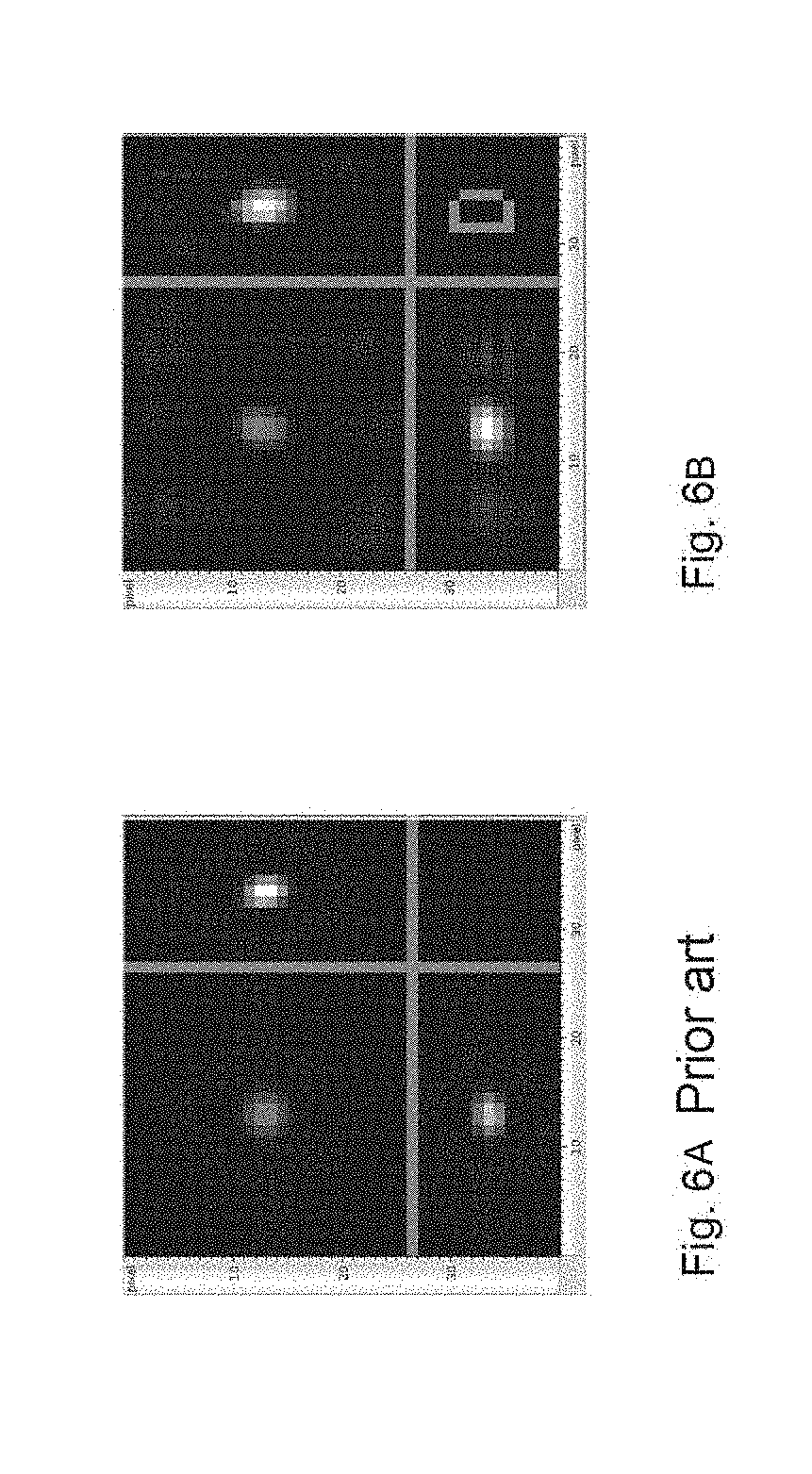
[0042] FIG. 6A shows projections of MPI image data, generated using a method according to the prior art.
[0043] FIG. 6B shows MPI image data of projections, generated using the method according to the invention.
DETAILED DESCRIPTION
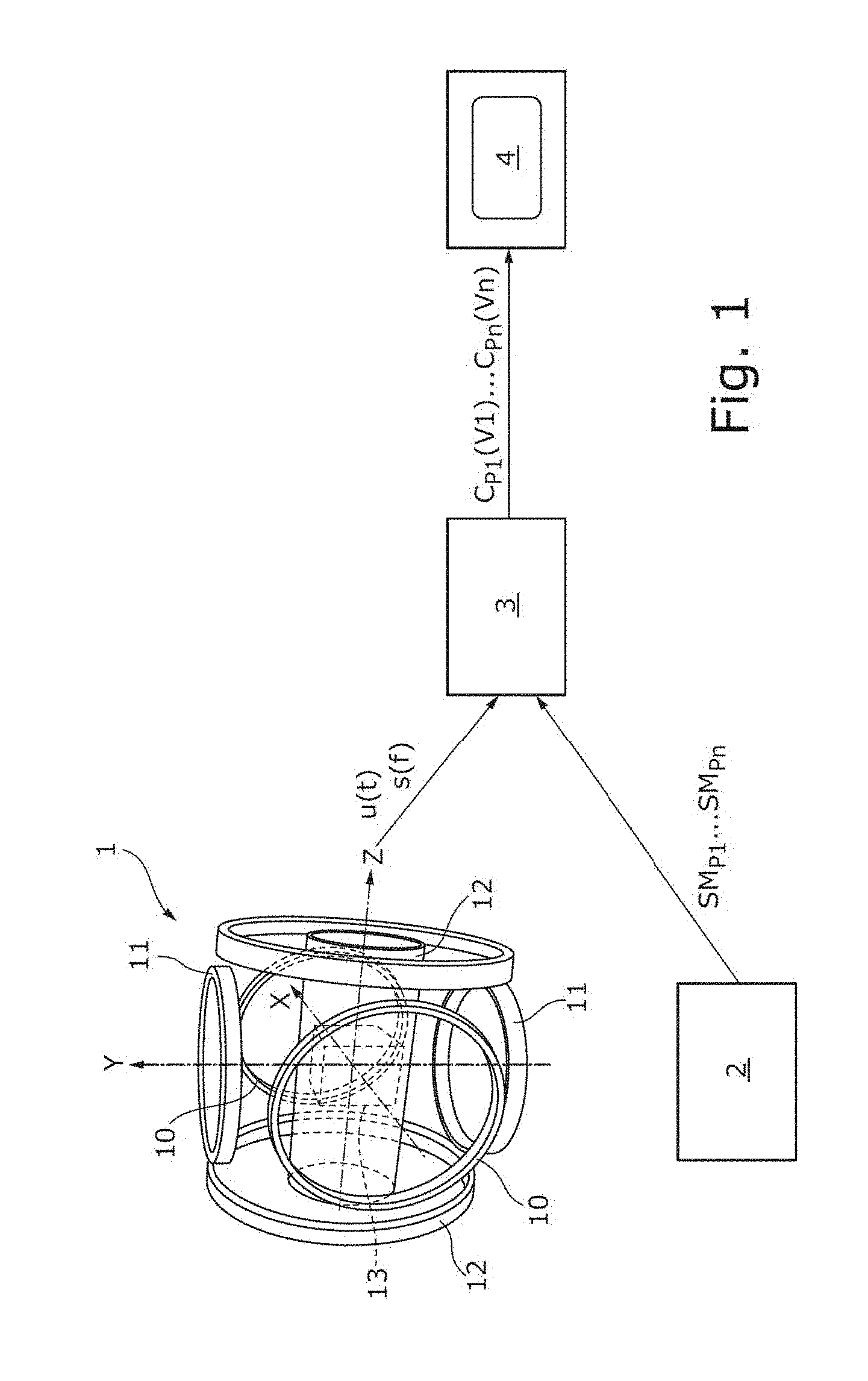
[0044] The system according to the invention is shown in FIG. 1 and comprises an MPI installation 1 with coil arrangements 10, 11, 12 for producing a spatially dependent magnetic field and a magnetic drive field within an examination volume 13, as is known from U.S. Pat. No. 9 364 165 B2, for example. MPI signal data u(t) (signal data in the time domain) or s(f) (signal data in the frequency domain) are detected by the MPI installation 1. Moreover, the system according to the invention comprises a device 2 for providing projected system matrices SM.sub.P1 . . . SM.sub.Pn. The projected system matrices SM.sub.P1 . . . SM.sub.Pn and the MPI signal data u(t) or s(f) are fed to a reconstruction device 3 (e.g., a linear solver) for reconstructing MPI image data c.sub.P1(v.sub.1) . . . c.sub.Pn(v.sub.n) from the MPI signal data u(t) or s(f) and the projected system matrices SM.sub.P1 . . . SM.sub.Pn, as shown in FIG. 3. The MPI image data c.sub.P1(v.sub.1) . . . c.sub.Pn(v.sub.n) are presented on an indicator apparatus 4 of the system according to the invention. The device 2 for providing a projected system matrix can be an electronic storage medium, in which a projected system matrix is stored, or a stored computer program that can be used to generate the projected system matrix along a projection direction.
[0045] FIG. 2 shows the procedure of a method according to the prior art, in which an MPI image data record c(r) is initially produced with the aid of MPI signal data s(f) and a system matrix SM(r,f) within the scope of a reconstruction operation R. Then, image projections c.sub.P1(v.sub.1)' . . . c.sub.Pn(v.sub.n)' can be produced along different projection directions within the scope of a projection operation P.
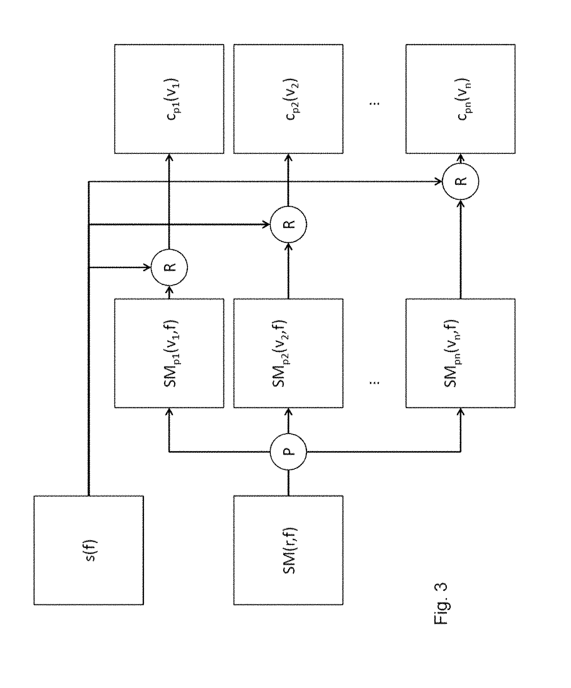
[0046] The method according to the invention is illustrated in FIG. 3. Here, the projection operation P is carried out before the reconstruction operation R. The system matrix SM(r,f) can be projected along at least one projection direction, as a result of which projected system matrices SM.sub.P1(v.sub.1,f) . . . SM.sub.Pn(v.sub.n,f) are generated. These projected system matrices SM.sub.P1(v.sub.1,f) . . . SM.sub.Pn(v.sub.n,f) are then used for the reconstruction operation R to reconstruct the MPI image data c.sub.P1(v.sub.1) . . . c.sub.Pn(v.sub.n) from the MPI signal data s(f). This reduces the amount of data used for the reconstruction operation R, even when a plurality of projected system matrices SM.sub.P1(v.sub.1,f) . . . SM.sub.Pn(v.sub.n,f) are produced.
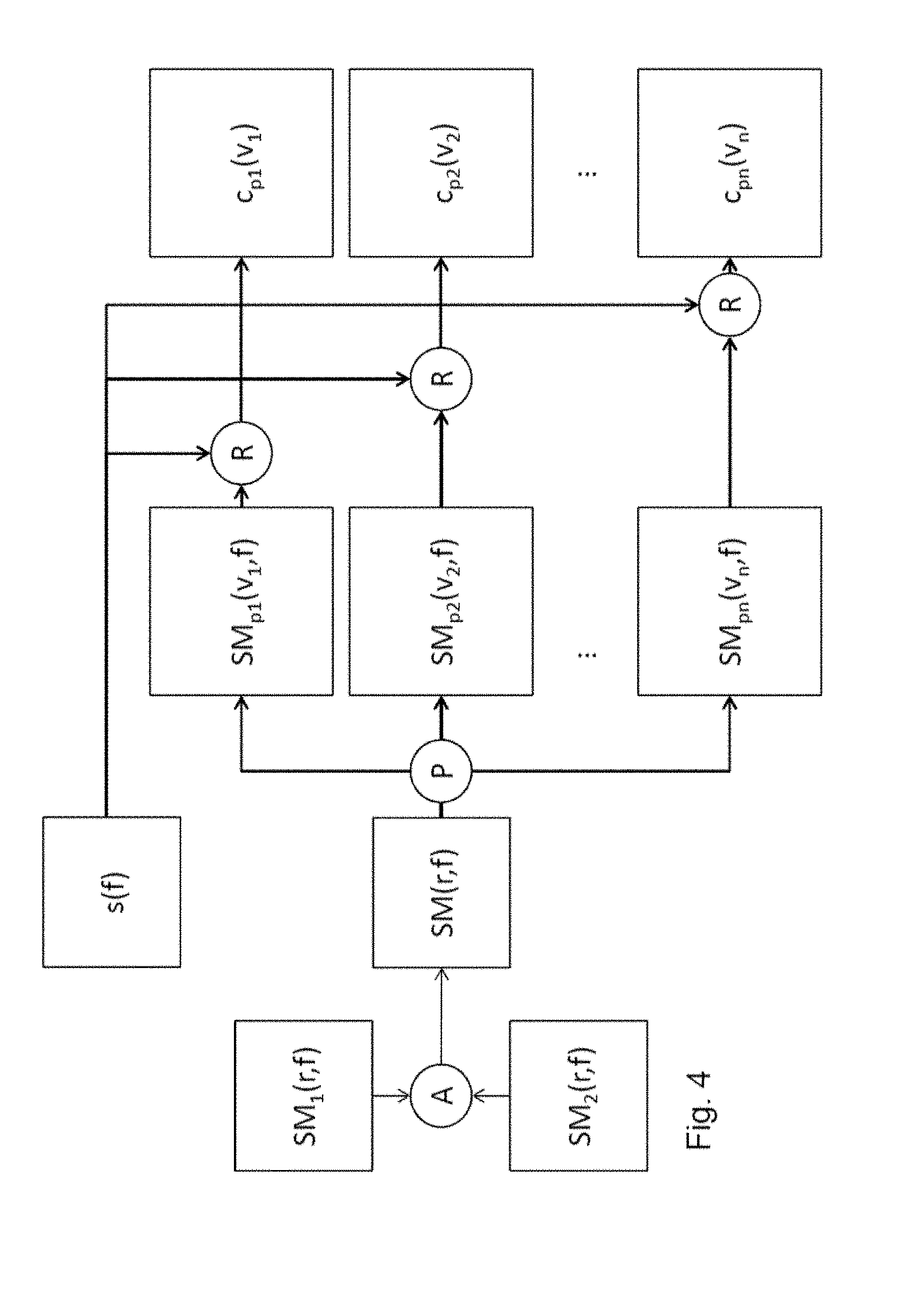
[0047] FIG. 4 shows a specific variant of the method according to the invention, in which the system matrix SM(r,f) is not directly measured or simulated but instead obtained by mathematical operation (in this case: addition) applied to two system matrices SM.sub.1(r,f), SM.sub.2(r,f) and subsequently subjected to the projection operation P. In this way, projections of the local overall concentration distribution of magnetic particles can be established independently of the particle class. Such a projection of the local overall concentration distribution can be helpful, for example for observing a catheter to be inserted into a vein, since the catheter tip may be coated with magnetic particles of different particle classes (e.g., different particle sizes) and all magnetic particles applied to the catheter tip should contribute to localizing the catheter tip. By combining the system matrices SM.sub.1(r,f), SM.sub.2(r,f) prior to the projection operation, the computational outlay is further reduced.
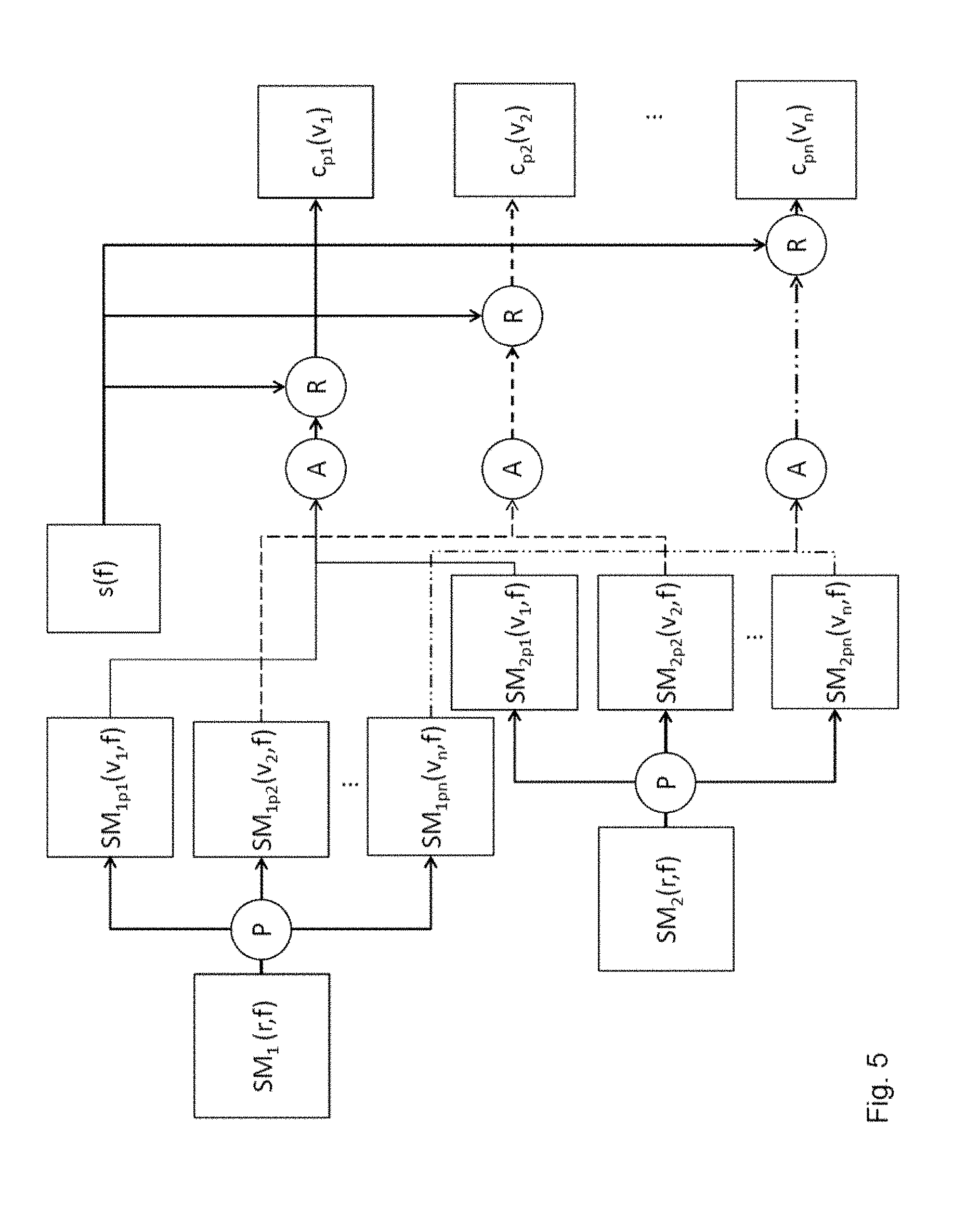
[0048] FIG. 5 shows a further variant of the method according to the invention, in which projections are created for a multi-parameter space. To this end, a system matrix SM.sub.1(r,f), SM.sub.2(r,f) is established in each case for different particle classes (e.g., for different particle types). The desired number n of spatial projections SM.sub.1p1(v.sub.1,f), SM.sub.1p2(v.sub.2,f), . . . , SM.sub.1pn(v.sub.nf); SM.sub.2p1(v.sub.1,f), SM.sub.2p2(v.sub.2,f), . . . , SM.sub.2pn(v.sub.n,f) is generated for each system matrix SM.sub.1(r,f), SM.sub.2(r,f). The projected system matrices that were projected along the same projection direction are appended and form an extended (appended) projected system matrix (not illustrated). In the shown example, n projected system matrices are generated for two SM.sub.1(r,f), SM.sub.2(r,f), said projected system matrices then being used to form n appended projected system matrices. Thus, the appended projected system matrices each consist of two projected system matrices, which result from projections of different system matrices along the same projection direction. Finally, the appended projected system matrices are used to reconstruct the MPI image data cp.sub.1(v1), cp.sub.2(v2), cp.sub.3(v3), with the MPI image data having a plurality of (in this case: two) sub-projections. Each sub-projection comprises image data of a particle class for the same predetermined examination volume (multi-parameter space). Thus, for example, the concentration of particles of a certain particle class within the examination volume can be represented in a sub-projection.
[0049] FIG. 6A shows MPI image data of projections that were produced through a known method (FIG. 6A) and FIG. 6B shows the method according to the invention (FIG. 6B). Shown here is the reconstruction of a 3D data record of a punctiform sample, in each case projected in the Z- (top left), X- (top right) and Y-directions (bottom left). Only very minor differences in the shown 2D images can be made out between the method according to the prior art and the method according to the invention. This shows that reliably projected image data can be established using the method according to the invention, for example for real-time measurements.
CITATIONS
[0050] [Stehning] Stehning et al. "Simultaneous Magnetic Particle Imaging (MPI) and Temperature Mapping Using Multi-Color MPI." International Journal on Magnetic Particle Imaging 2, no. 2 (2016). [0051] https://journal.iwmpi.org/index.php/iwmpi/article/view/34; FIG. 6 [0052] [Gruttner] Gruttner et al. "On the formulation of the image reconstruction problem in magnetic particle imaging"; Biomedical Engineering/Biomedizinische Technik; Volume 58, Issue 6 (December 2013); [0053] DOI: https://doi.org/10.1515/bmt-2012-0063) [0054] [Knopp] Knopp et al. "Sparse Reconstruction of the Magnetic Particle Imaging System Matrix" EEE Transactions on Medical Imaging; Volume: 32 Issue: 8; [0055] DOI: 10.1109/TMI.2013.2258029 [0056] U.S. Pat. No. 9,364,165 B2
LIST OF REFERENCE SIGNS
[0056] [0057] 1 MPI installation [0058] 2 Device for providing projected system matrices [0059] 3 Reconstruction device (linear solver) [0060] 4 Indicator apparatus [0061] 11, 12, 13 Coil arrangements [0062] 14 Examination volume [0063] c(r) MPI image data record [0064] c.sub.P1(v.sub.1) . . . c.sub.Pn(v.sub.n) MPI image data of the projections [0065] c.sub.P1(v.sub.1)' . . . c.sub.Pn(v.sub.n)' Projected MPI image data according to the prior art [0066] P Projection operation [0067] R Reconstruction operation [0068] A Addition parameter [0069] SM(r,f) System matrix [0070] SM.sub.P1(v.sub.1,f) . . . SM.sub.Pn(v.sub.n,f) Projected system matrices [0071] u(t) MPI signal data (time domain) [0072] s(f) MPI signal data (frequency domain)
* * * * *
References
D00000
D00001
D00002
D00003
D00004
D00005
D00006
P00001
XML
uspto.report is an independent third-party trademark research tool that is not affiliated, endorsed, or sponsored by the United States Patent and Trademark Office (USPTO) or any other governmental organization. The information provided by uspto.report is based on publicly available data at the time of writing and is intended for informational purposes only.
While we strive to provide accurate and up-to-date information, we do not guarantee the accuracy, completeness, reliability, or suitability of the information displayed on this site. The use of this site is at your own risk. Any reliance you place on such information is therefore strictly at your own risk.
All official trademark data, including owner information, should be verified by visiting the official USPTO website at www.uspto.gov. This site is not intended to replace professional legal advice and should not be used as a substitute for consulting with a legal professional who is knowledgeable about trademark law.