Ignition Switch Assembly For A Cooktop Appliance
Nellaiappan; Vedamoorthy ; et al.
U.S. patent application number 15/923047 was filed with the patent office on 2019-09-19 for ignition switch assembly for a cooktop appliance. The applicant listed for this patent is Haier US Appliance Solutions, Inc.. Invention is credited to Eric Collins, Vedamoorthy Nellaiappan.
| Application Number | 20190285281 15/923047 |
| Document ID | / |
| Family ID | 67905322 |
| Filed Date | 2019-09-19 |
| United States Patent Application | 20190285281 |
| Kind Code | A1 |
| Nellaiappan; Vedamoorthy ; et al. | September 19, 2019 |
IGNITION SWITCH ASSEMBLY FOR A COOKTOP APPLIANCE
Abstract
An ignition switch assembly includes an electronics compartment defined by a lower housing and an upper housing for receiving an ignition switch. A cam actuator is coupled to a gas control shaft and is positioned at least partially within the electronics compartment for selectively engaging the ignition switch. The cam actuator includes a center hub that extends through a top aperture defined in the upper housing and an outer hub positioned around the center hub and having an outer hub diameter that is larger than the top aperture. A connecting wall extends between the center hub and the outer hub to define a circumferential groove for collecting spilled fluid and directing it toward a drain port defined in the lower housing.
| Inventors: | Nellaiappan; Vedamoorthy; (LaFayette, GA) ; Collins; Eric; (Ringgold, GA) | ||||||||||
| Applicant: |
|
||||||||||
|---|---|---|---|---|---|---|---|---|---|---|---|
| Family ID: | 67905322 | ||||||||||
| Appl. No.: | 15/923047 | ||||||||||
| Filed: | March 16, 2018 |
| Current U.S. Class: | 1/1 |
| Current CPC Class: | F24C 3/10 20130101; F23N 1/007 20130101; F24C 3/122 20130101; F24C 3/126 20130101 |
| International Class: | F24C 3/10 20060101 F24C003/10; F24C 3/12 20060101 F24C003/12; F23N 1/00 20060101 F23N001/00 |
Claims
1. An ignition switch assembly defining an axial direction and a radial direction, the ignition switch assembly comprising: a lower housing defining a drain port; an upper housing positioned over the lower housing to define an electronics compartment therebetween, the upper housing defining a top aperture having a top aperture diameter; and a cam actuator positioned at least partially within the electronics compartment, the cam actuator comprising: a center hub that extends along the axial direction and defines a center hub diameter that is less than or equal to the top aperture diameter; an outer hub positioned around the center hub and defining an outer hub diameter that is greater than the top aperture diameter; and a connecting wall extending substantially along the radial direction between the center hub and the outer hub, wherein the center hub, the outer hub, and the connecting wall define a circumferential groove for collecting spilled fluid.
2. The ignition switch assembly of claim 1, wherein the upper housing defines a circumferential flange around the top aperture that extends at least partially into the circumferential groove.
3. The ignition switch assembly of claim 2, wherein the circumferential flange extends substantially along the axial direction and has a flange diameter that is substantially equivalent to the center hub diameter.
4. The ignition switch assembly of claim 2, wherein a collection gap is defined between bottom edge of the circumferential flange and the connecting wall.
5. The ignition switch assembly of claim 4, wherein the collection gap is greater than 0.025 inches measured along the axial direction.
6. The ignition switch assembly of claim 1, wherein a top edge of the outer hub is positioned proximate the upper housing to form a fluid seal therebetween.
7. The ignition switch assembly of claim 6, wherein a circular seal is positioned between the top edge of the outer hub and the upper housing to prevent an overflow of the spilled fluid from passing into the electronics compartment.
8. The ignition switch assembly of claim 1, wherein the center hub defines one or more axially extending slots opening up at least partially into the circumferential groove, wherein the slots and circumferential groove provide a flow path for directing the spilled fluid toward the drain port of the lower housing.
9. The ignition switch assembly of claim 1, wherein the upper housing has an upper surface that slopes downward from the top aperture relative to the radial direction.
10. The ignition switch assembly of claim 1, wherein the center hub of the cam actuator defines a keyed aperture for receiving a gas control shaft, the gas control shaft being rotatable about the axial direction and rotationally fixed relative to the cam actuator.
11. The ignition switch assembly of claim 10, comprising: an ignition switch mounted within the electronics compartment, the cam actuator being configured for actuating an electrical contact of the ignition switch.
12. The ignition switch assembly of claim 10, wherein a control knob is mounted onto the gas control shaft for regulating a position of a gas control valve.
13. The ignition switch assembly of claim 12, comprising: a cylindrical shield positioned around the gas control shaft and extending along the axial direction at least partially between the upper housing and the control knob.
14. The ignition switch assembly of claim 13, wherein the cylindrical shield is defined by upper housing and extends toward the control knob along the axial direction.
15. The ignition switch assembly of claim 13, wherein the cylindrical shield is defined by the control knob and extends toward the upper housing along the axial direction.
16. A control knob assembly for regulating a power level of a heating element of a cooktop appliance, the control knob assembly defining an axial direction and a radial direction, the control knob assembly comprising: a control knob rotatable about the axial direction; a gas control valve for regulating a flow of fuel to the heating element; a gas control shaft extending between and operably coupling the control knob and the gas control valve; and an ignition switch assembly operably coupled to the gas control shaft, the ignition switch assembly comprising: a lower housing defining a drain port; an upper housing positioned over the lower housing to define an electronics compartment therebetween, the upper housing defining a top aperture having a top aperture diameter; and a cam actuator positioned at least partially within the electronics compartment, the cam actuator comprising a center hub that extends along the axial direction and defines a center hub diameter that is less than or equal to the top aperture diameter; an outer hub positioned around the center hub and defining an outer hub diameter that is greater than the top aperture diameter; and a connecting wall extending substantially along the radial direction between the center hub and the outer hub, wherein the center hub, the outer hub, and the connecting wall define a circumferential groove for collecting spilled fluid.
17. The control knob assembly of claim 16, wherein the upper housing defines a circumferential flange around the top aperture that extends at least partially into the circumferential groove.
18. The control knob assembly of claim 17, wherein the circumferential flange extends substantially along the axial direction and has a flange diameter that is substantially equivalent to the center hub diameter.
19. The control knob assembly of claim 17, wherein a collection gap is defined between bottom edge of the circumferential flange and the connecting wall.
20. The control knob assembly of claim 16, wherein the center hub defines one or more axially extending slots opening up at least partially into the circumferential groove, wherein the slots and circumferential groove provide a flow path for directing the spilled fluid toward the drain port of the lower housing.
Description
FIELD OF THE INVENTION
[0001] The present subject matter relates generally to cooktops appliances and more particularly to a spill resistant ignition switch assemblies for cooktop appliances.
BACKGROUND OF THE INVENTION
[0002] Control knobs are commonly used on a variety of commercial and residential appliances to control an operating condition of the appliance. Control knobs are particularly common on cooking appliances, such as stoves or cooktops. Various shapes and sizes can be used depending upon, e.g., the intended application, aesthetics, and other factors.
[0003] Conventional cooktops have at least one heating element positioned at a cooktop surface for use in heating or cooking an object, such as a cooking utensil and its contents. Control knobs are typically used to adjust the power level of the heating element--and thus the amount of heat delivered by the heating element. Generally, control knobs are positioned on a top panel which defines one or more apertures through which the control knob or a gas control shaft extends to engage a controller, an ignition switch, and/or gas valve behind the top panel.
[0004] Notably, these apertures provide a path for spilled fluids to reach sensitive control electronics and components, which may result in ignition switch or valve failure. Therefore, conventional ignition switches include splash guards, shields, or other features for preventing spilled fluids from reaching sensitive components such as an ignition switch and electrical contacts. However, such spill control features are often complex, including multiple parts that increase costs and assembly time. In addition, such spill control features are only partially effective, often permitting spills to enter the switch housing resulting in an increased likelihood of failure and a potential for operability issues when regulating the heating element.
[0005] Accordingly, a cooktop appliance having a control knob assembly with improved spill resistant features is desirable. More particularly, an ignition switch assembly that is easy to install and effectively routes any flow of spilled fluids away from sensitive electronic components would be particularly beneficial.
BRIEF DESCRIPTION OF THE INVENTION
[0006] Aspects and advantages of the invention will be set forth in part in the following description, or may be apparent from the description, or may be learned through practice of the invention.
[0007] In one exemplary embodiment, an ignition switch assembly defining an axial direction and a radial direction is provided. The ignition switch assembly includes a lower housing defining a drain port and an upper housing positioned over the lower housing to define an electronics compartment therebetween, the upper housing defining a top aperture having a top aperture diameter. A cam actuator is positioned at least partially within the electronics compartment. The cam actuator includes a center hub that extends along the axial direction and defines a center hub diameter that is less than or equal to the top aperture diameter and an outer hub positioned around the center hub and defining an outer hub diameter that is greater than the top aperture diameter. A connecting wall extends substantially along the radial direction between the center hub and the outer hub, wherein the center hub, the outer hub, and the connecting wall define a circumferential groove for collecting spilled fluid.
[0008] In another exemplary embodiment, a control knob assembly for regulating a power level of a heating element of a cooktop appliance is provided. The control knob assembly defines an axial direction and a radial direction. The control knob assembly includes a control knob rotatable about the axial direction, a gas control valve for regulating a flow of fuel to the heating element, and a gas control shaft extending between and operably coupling the control knob and the gas control valve. An ignition switch assembly is operably coupled to the gas control shaft, the ignition switch assembly including a lower housing defining a drain port and an upper housing positioned over the lower housing to define an electronics compartment therebetween, the upper housing defining a top aperture having a top aperture diameter. A cam actuator is positioned at least partially within the electronics compartment, the cam actuator comprising a center hub that extends along the axial direction and defines a center hub diameter that is less than or equal to the top aperture diameter; an outer hub positioned around the center hub and defining an outer hub diameter that is greater than the top aperture diameter; and a connecting wall extending substantially along the radial direction between the center hub and the outer hub, wherein the center hub, the outer hub, and the connecting wall define a circumferential groove for collecting spilled fluid.
[0009] These and other features, aspects and advantages of the present invention will become better understood with reference to the following description and appended claims. The accompanying drawings, which are incorporated in and constitute a part of this specification, illustrate embodiments of the invention and, together with the description, serve to explain the principles of the invention.
BRIEF DESCRIPTION OF THE DRAWINGS
[0010] A full and enabling disclosure of the present invention, including the best mode thereof, directed to one of ordinary skill in the art, is set forth in the specification, which makes reference to the appended figures.
[0011] FIG. 1 provides a perspective view of a cooktop appliance according to an exemplary embodiment of the present subject matter.
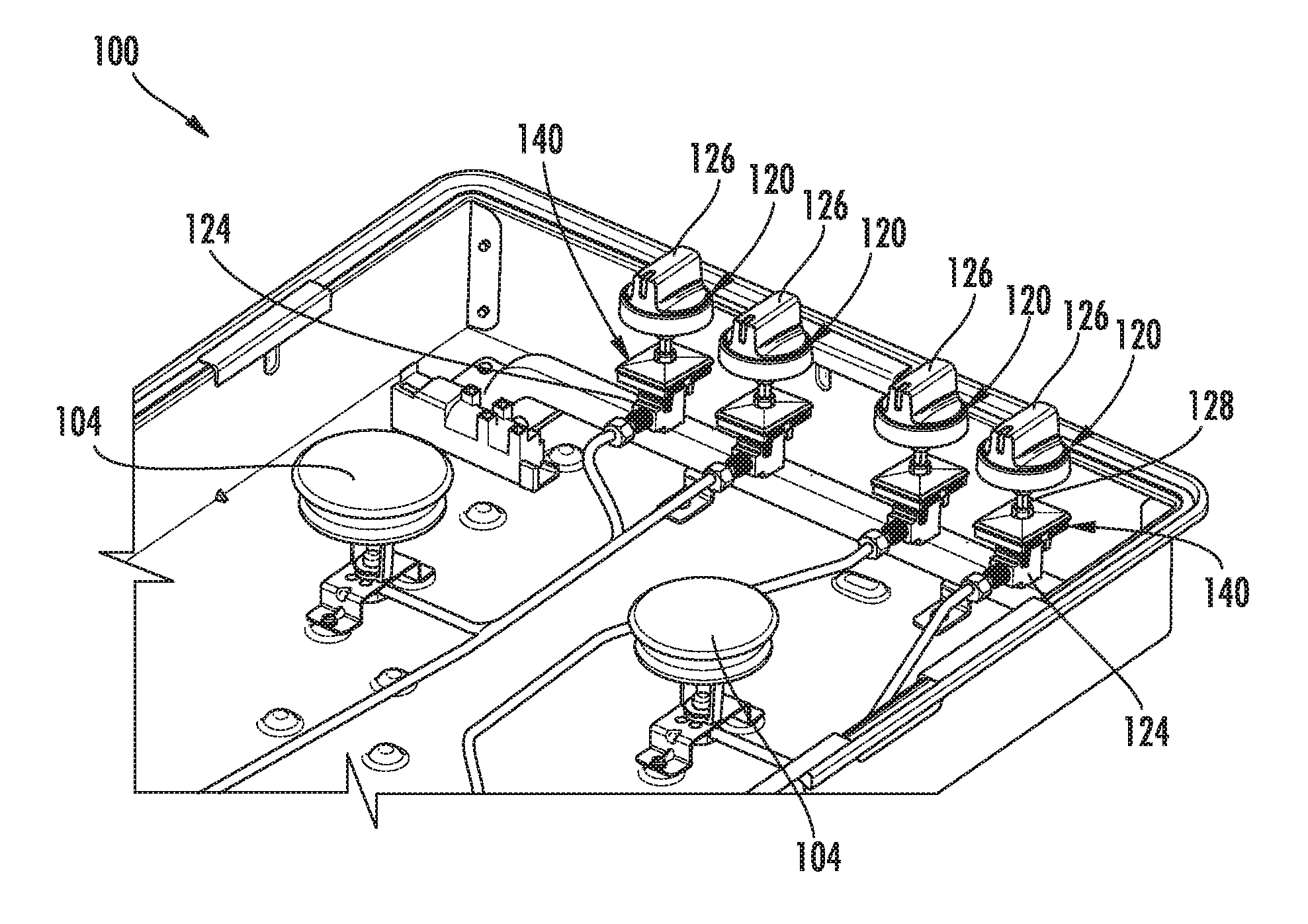
[0012] FIG. 2 provides a perspective view of the exemplary cooktop appliance of FIG. 1 with the top panel removed to reveal various gas regulating features according to an exemplary embodiment of the present subject matter.
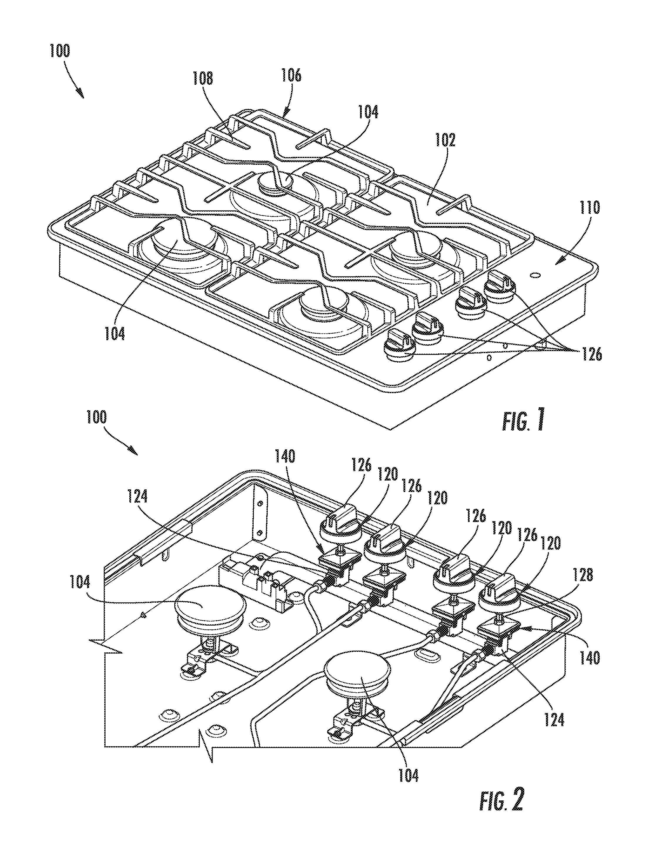
[0013] FIG. 3 provides a perspective view of a control knob assembly that may be used with the exemplary cooktop appliance of FIG. 1 according to an exemplary embodiment of the present subject matter.
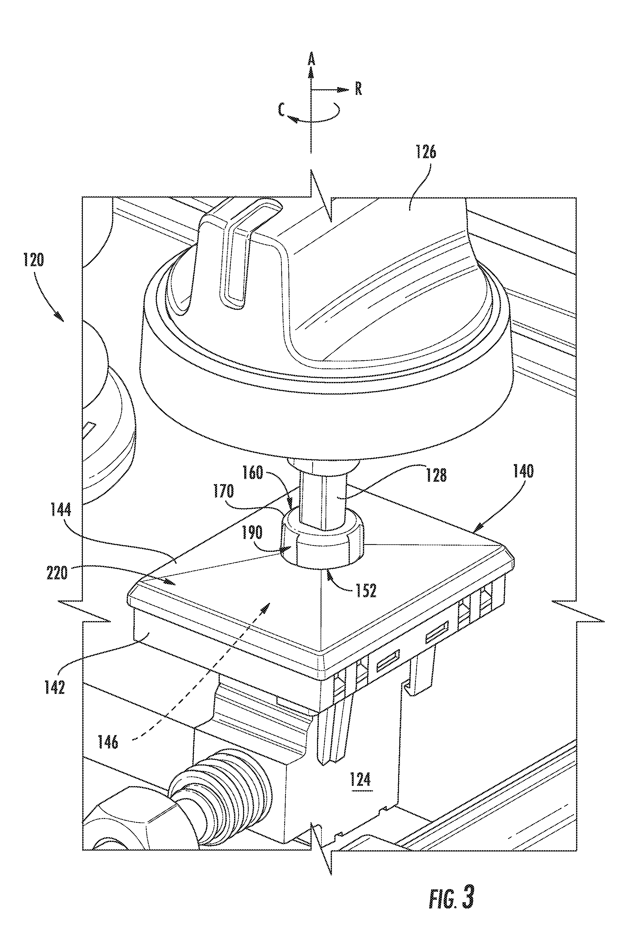
[0014] FIG. 4 provides a perspective view of an exemplary ignition switch assembly that may be used with the exemplary control knob assembly of FIG. 3.
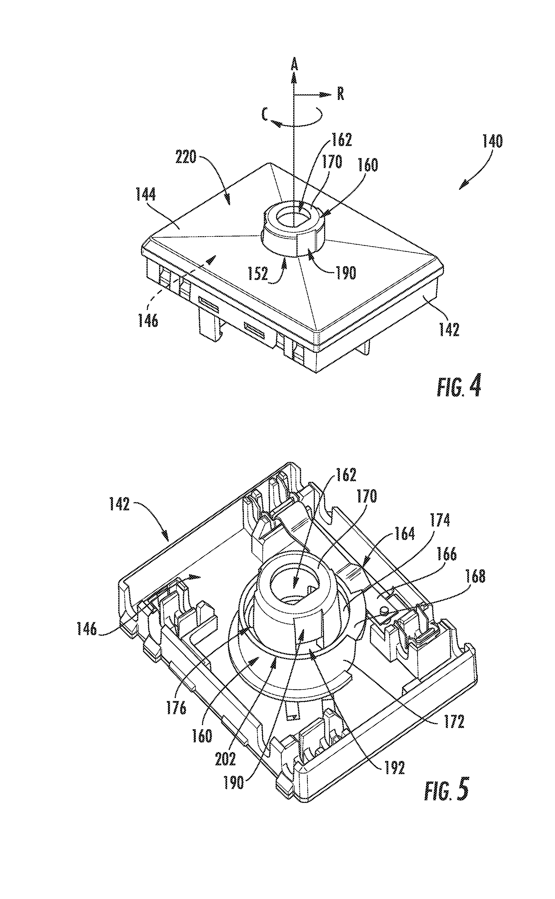
[0015] FIG. 5 provides a perspective view of the lower housing of the exemplary ignition switch assembly of FIG. 4 with a top cover removed for clarity.
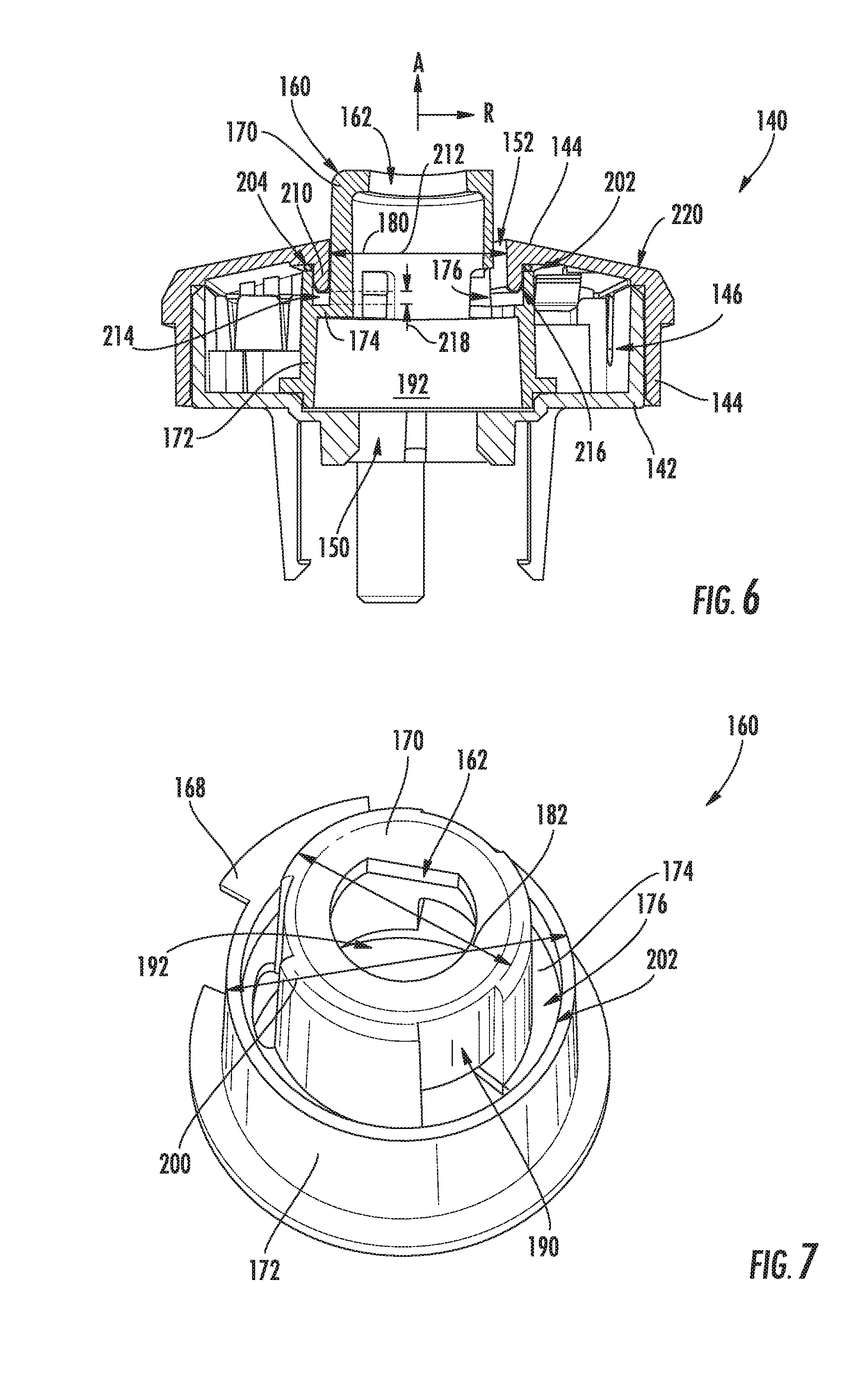
[0016] FIG. 6 provides a cross sectional view of the exemplary ignition switch assembly of FIG. 4.
[0017] FIG. 7 provides a perspective view of a cam actuator of the exemplary ignition switch assembly of FIG. 4.
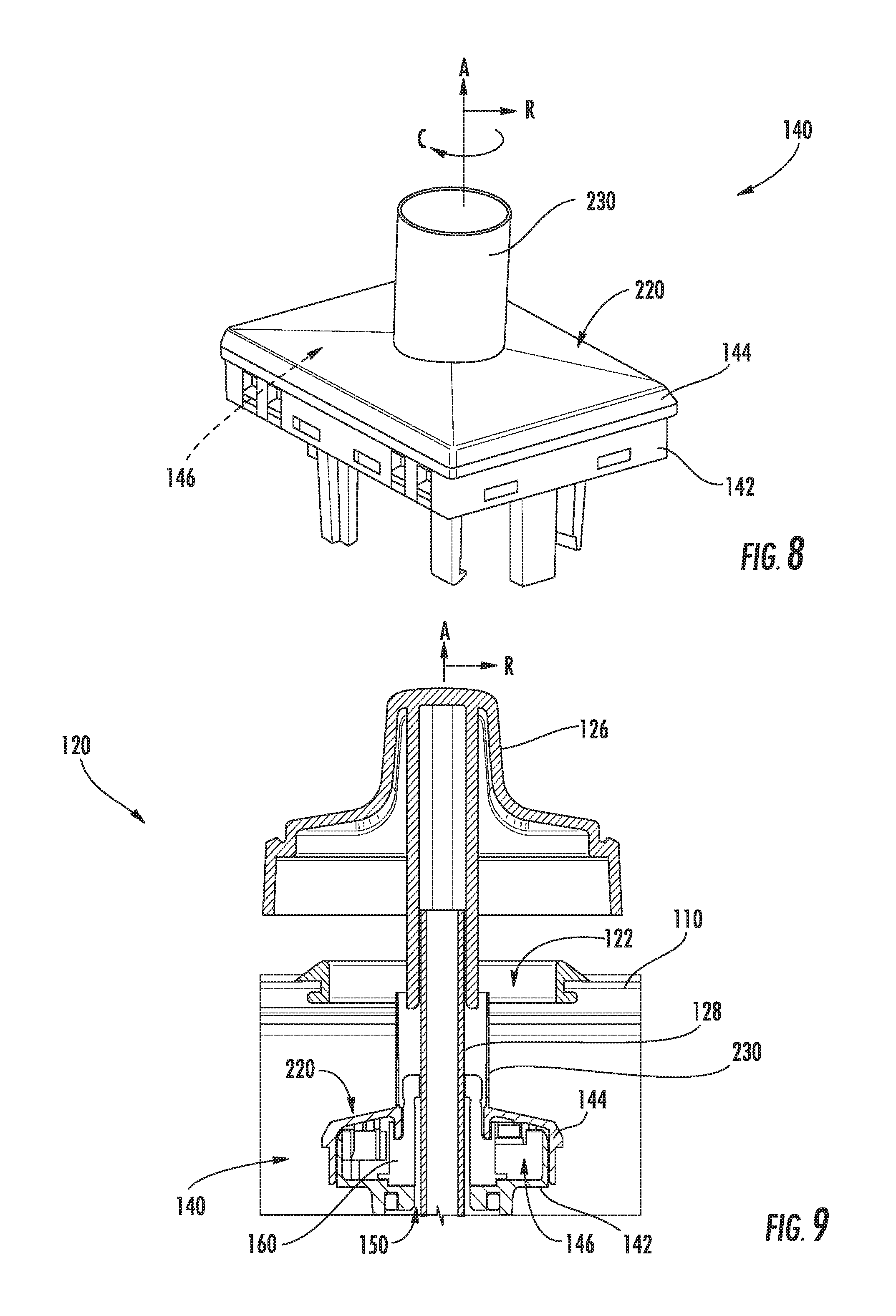
[0018] FIG. 8 provides a perspective view of an ignition switch assembly that may be used with the exemplary cooktop appliance of FIG. 1 according to another exemplary embodiment of the present subject matter.
[0019] FIG. 9 provides a cross sectional view of a control knob assembly that may be used with the exemplary cooktop appliance of FIG. 1 according to an exemplary embodiment of the present subject matter.
[0020] Repeat use of reference characters in the present specification and drawings is intended to represent the same or analogous features or elements of the present invention.
DETAILED DESCRIPTION OF THE INVENTION
[0021] Reference now will be made in detail to embodiments of the invention, one or more examples of which are illustrated in the drawings. Each example is provided by way of explanation of the invention, not limitation of the invention. In fact, it will be apparent to those skilled in the art that various modifications and variations can be made in the present invention without departing from the scope or spirit of the invention. For instance, features illustrated or described as part of one embodiment can be used with another embodiment to yield a still further embodiment. Thus, it is intended that the present invention covers such modifications and variations as come within the scope of the appended claims and their equivalents.
[0022] The present disclosure relates generally to a control knob assembly and an ignition switch assembly for a cooktop appliance 100. Although cooktop appliance 100 is used below for the purpose of explaining the details of the present subject matter, one skilled in the art will appreciate that the present subject matter may apply to any other suitable consumer or commercial appliance. For example, the exemplary control knob assemblies described below may be used on other types of cooking appliances, such as ranges or oven appliances, or on dishwashing appliances, washing machines, clothes dryers, or any other consumer or commercial appliance that operates at least in part based on user input through a control knob. Cooktop appliance 100 is used in the discussion below only for the purpose of explanation, and such use is not intended to limit the scope of the present disclosure in any manner.
[0023] FIG. 1 illustrates an exemplary embodiment of a cooktop appliance 100 of the present disclosure. Cooktop appliance 100 may be, e.g., fitted integrally with a surface of a kitchen counter, may be configured as a slide-in cooktop unit, or may be a part of a free-standing range cooking appliance. Cooktop appliance 100 includes a top panel 102 that includes one or more heating sources, such as heating elements 104 for use in, e.g., heating or cooking. Top panel 102, as used herein, refers to any upper surface of cooktop appliance 100 on which utensils may be heated and therefore food cooked. In general, top panel 102 may be constructed of any suitably rigid and heat resistant material capable of supporting heating elements 104, cooking utensils, and/or other components of cooktop appliance 100. By way of example, top panel 102 may be constructed of enameled steel, stainless steel, glass, ceramics, and combinations thereof.
[0024] According to the illustrated embodiment, cooktop appliance 100 is a gas cooktop and heating elements 104 are gas burners. As illustrated, heating elements 104 are positioned within top panel 102 and have various sizes, as shown in FIG. 1, so as to provide for the receipt of cooking utensils (i.e., pots, pans, etc.) of various sizes and configurations and to provide different heat inputs for such cooking utensils. In addition, cooktop appliance 100 may include one or more grates 106 configured to support a cooking utensil, such as a pot, pan, etc. In general, grates 106 include a plurality of elongated members 108, e.g., formed of cast metal, such as cast iron. The cooking utensil may be placed on the elongated members 108 of each grate 106 such that the cooking utensil rests on an upper surface of elongated members 108 during the cooking process. Heating elements 104 are positioned underneath the various grates 106 such that heating elements 104 provide thermal energy to cooking utensils above top panel 102 by combustion of fuel below the cooking utensils.
[0025] Although heating elements 104 are illustrated herein as gas burners, it should be appreciated that according to various alternative embodiments, heating elements 104 may employ any suitable method for heating or cooking an object, such as a cooking utensil and its contents. For example, cooktop appliance 100 may be a gas cooktop, a radiant smooth top cooktop, an electric coil cooktop, an induction cooktop, etc. Thus, according to alternative embodiments, heating elements 104 use another heat transfer method, such as electric coils or induction elements, to heat the cooking utensil.
[0026] Moreover, the configuration of cooktop appliance 100 and top panel 102 may vary according to the type of cooktop and heating elements. For example, in smooth top (e.g., glass) and induction cooktop applications, top panel 102 may directly support the cooking utensils, such that no grate 106 is needed. In this regard, top panel 102 may be a constructed of a ceramic glass for supporting the cooking utensil and heating element 104 may be positioned within or below top panel 102. By contrast, in an electric coil cooktop, the heating element 104 (e.g., the electrical coil) directly supports the cooking utensil. Other configurations are possible and within the scope of the present subject matter.
[0027] According to the illustrated exemplary embodiment, a user interface panel or control panel 110 is located within convenient reach of a user of cooktop appliance 100. Referring now also to FIG. 2, according to the illustrated exemplary embodiment, control panel 110 includes control knob assemblies 120 that are each associated with one of heating elements 104. Control knob assemblies 120 allow the user to activate each heating element 104 and regulate the amount of heat input each heating element 104 provides to a cooking utensil located thereon, as described in more detail below. Control panel 110 may also be provided with one or more graphical display devices, such as a digital or analog display device designed to provide operational feedback to a user.
[0028] According to the illustrated embodiment, control knob assemblies 120 are located within control panel 110 of cooktop appliance 100. However, it should be appreciated that this location is used only for the purpose of explanation, and that other locations and configurations of control panel 110 and control knob assemblies 120 are possible and within the scope of the present subject matter. Indeed, according to alternative embodiments, control knob assemblies 120 may instead be located directly on top panel 102 or elsewhere on cooktop appliance 100, e.g., on a backsplash, front bezel, or any other suitable surface of cooktop appliance 100.
[0029] Referring now generally to FIGS. 2 and 3, a control knob assembly 120 that may be used with cooktop appliance 100 will be described in more detail. Although the discussion below refers to an exemplary control knob assembly 120, it should be appreciated that the features and configurations described may be used for other knob assemblies in other cooking appliances or consumer appliances as well. For example, control knob assembly 120 may be positioned elsewhere within cooktop appliance 100, may have different components or configurations, and use alternative ignition switch assemblies. Other variations and modifications of the exemplary embodiment described below are possible, and such variations are contemplated as within the scope of the present subject matter.
[0030] As illustrated, control knob assembly 120 generally defines an axial direction A, a radial direction R, and a circumferential direction C. In this regard, for example, control knob assembly 120 generally passes through a panel aperture 122 (see FIG. 9) defined in control panel 110 along the axial direction A, which is substantially normal to control panel 110. However, according to alternative embodiments, panel aperture 122 may be any suitable size or shape and may be positioned in any suitable surface of cooktop appliance 100.
[0031] As best shown in FIG. 2, control knob assembly 120 includes a gas control valve 124 that is positioned below user interface panel 110 for regulating a flow of fuel to heating element 104. According to an exemplary embodiment, control knob assembly 120 further includes a control knob 126 that is manipulated by a user for regulating the amount of heat delivered by a corresponding heating element 104 on top panel 102. In this regard, control knob 126 is generally rotatable about the axial direction A and is operably coupled to gas control valve 124 through a gas control shaft 128. In this regard, rotating control knob 126 a certain amount in the circumferential direction C rotates control shaft 128 the same amount in the circumferential direction C, thereby controlling gas control valve 124.
[0032] Although the described exemplary embodiment illustrates gas control valve 124 for regulating a flow of gas to a gas burner, it should be appreciated that aspects of the present subject matter may be used to regulate other types of heating elements, such as electric or induction heating elements. Thus, by contrast, if heating elements 104 are electric or induction heating elements, control shaft 128 could instead be coupled to an electronic regulator, e.g., an infinite switch that controls the amount of electrical power delivered to heating element 104.
[0033] As used herein, control knob 126 may refer to any configuration of rotary dial, and not just one having a circular base, as shown in FIGS. 1 through 3. For example, the present disclosure contemplates exemplary embodiments wherein knobs 126 have a rectangular base, an oval base, or any other shape having one or more curved lines, straight lines, or both. Furthermore, although control knob 126 is illustrated as controlling the power level of heating element 104 of cooktop appliance 100, one skilled in the art will appreciate that aspects of the present disclosure may be used to control alternative operating conditions on other appliances. For example, according to alternative embodiments, control knob 126 may be used to regulate a wash time on a washing machine or to select a wash cycle on a dishwasher.
[0034] In order to provide an ignition spark to the gas burner heating elements 104, each control knob assembly 120 may further include an ignition switch assembly 140. As will be described in more detail below, ignition switch assembly 140 is generally coupled to gas control shaft 128 for providing an ignition spark when control knob 126 is in the desired position (e.g., the lighting or ignition position). Ignition switch assembly 140 is positioned below top panel 102 and is generally exposed to fluid spills that might pass through panel aperture 122. Therefore, aspects of the present subject matter described below are intended to divert water from sensitive electronic components in order to prevent failure of ignition switch assembly 140.
[0035] Referring now generally to FIGS. 4 through 7, ignition switch assembly 140 will be described according to an exemplary embodiment of the present subject matter. In general, ignition switch assembly 140 defines an axial direction A, a radial direction R, and a circumferential direction C which correspond to the same directions for control knob assembly 120. According to the illustrated embodiment, ignition switch assembly 140 is positioned below top panel 102 and is operably coupled to the gas control shaft 128 between gas control valve 124 and control knob 126. However, it should be appreciated that according to alternative embodiments, ignition switch assembly 140 may be coupled to control knob 126 or gas control shaft 128 in any other suitable manner and at any other suitable location.
[0036] Ignition switch assembly 140 includes a lower housing 142 and an upper housing 144 which is positioned over lower housing 142 to define an electronics compartment 146 between lower housing 142 and upper housing 144. According to the illustrated embodiment, lower housing 142 and upper housing 144 are joined using a snap-fit mechanism. However, any suitable method for joining lower housing 142 and upper housing 144 may be used according to alternative embodiments. For example, lower housing 142 and upper housing 144 may be joined using any suitable mechanical fasteners, such as screws, bolts, rivets, plastic snaps, etc. Alternatively, glue, welding, interference-fit mechanisms, or any suitable combination thereof may join lower housing 142 and upper housing 144.
[0037] In order to permit gas control shaft 128 two pass through and generally engage ignition switch assembly 140, lower housing 142 may define a drain port 150 and upper housing 144 may define a top aperture 152 through which control shaft 128 may pass. As shown for example in FIGS. 3 and 9, drain port 150 and top aperture 152 are substantially circular holes defined about the axial direction A. Notably, top aperture 152 also provides a place where fluid inadvertently spilled during a cooking process may enter electronics compartment 146, potentially resulting in operability issues. Therefore, as described in more detail below, ignition switch assembly 140 includes features for directing the flow of spilled fluids toward drain port 150 where they may be safely drained without contacting any sensitive electronic components.
[0038] Ignition switch assembly 140 further includes a cam actuator 160 which is positioned at least partially within electronics compartment 146. In general, cam actuator 160 is rotatably mounted within the ignition switch assembly 140 and is operably coupled with gas control shaft 128. For example, cam actuator 160 may define a keyed aperture 162 for receiving gas control shaft 128 such that the cam actuator 160 is operatively coupled with gas control shaft 128. In this regard, for example, keyed aperture 162 may have a D-shaped cross section that is configured to receive control shaft 128, which has a corresponding D-shaped profile. Control knob 126 may define a similar keyed feature for receiving and engaging control shaft 128. In this manner, control shaft 128 rotates precisely with control knob 126 and cam actuator 160 with little or no lag. It should be noted that while keyed aperture 162 is described herein as being D-shaped, other shapes may be used so long as they rotationally link control shaft 128 and cam actuator 160.
[0039] As best shown in FIG. 5, ignition switch assembly 140 further includes an ignition switch 164 that is mounted within electronics compartment 146. More specifically, ignition switch 164 may include a flexible electrical contact 166 which is deflected by an actuating flange 168 defined by cam actuator 160 when a spark should be provided to ignite the flow of gas. In this manner, cam actuator 160 may be designed to actuate ignition switch 164 when rotated to the desired position (e.g., the ignition position).
[0040] Referring still to FIGS. 4 through 7, cam actuator 160 includes a center hub 170 that extends along the axial direction A, an outer hub 172 that is positioned around center hub 170, and a connecting wall 174 that extends substantially along the radial direction R between center hub 170 and outer hub 172. In this manner, center hub 170, outer hub 172, and connecting wall 174 generally define a circumferential groove 176 which may collect excess spilled fluid that passes through top aperture 152.
[0041] As best shown in FIG. 6, center hub 170 may extend through top aperture 152 and may form a substantially tight fit therein while permitting cam actuator 160 to rotate within electronics compartment 146. In this regard, for example, top aperture 152 may define a top aperture diameter 180 and center hub 170 may define a center hub diameter 182 that is less than or substantially equal to top aperture diameter 180. It should be appreciated that as used herein, terms of approximation, such as "approximately," "substantially," or "about," refer to being within a ten percent margin of error. In this manner, center hub 170 may extend through top aperture 152 toward top panel 102.
[0042] In order to provide a flow path for spilled fluids to pass through the ignition switch assembly 140 (e.g., instead of collecting therein), center hub 170 may further define one or more slots 190 that extends substantially along the axial direction A along outer surface of center hub 170. In addition, as illustrated, slots 190 open up at least partially into circumferential groove 176, such that spill fluid that collects within circumferential groove 176 may pass into slots 190 and fall out of ignition switch assembly 140 under the force of gravity. In this regard, for example, slots 190 may provide a direct flow path from top aperture 152, through slots 190 into an interior 192 of cam actuator 160. Notably, interior 192 of cam actuator 160 is positioned directly over drain port 150 such that the fluids may fall through ignition switch assembly 140 without contacting ignition switch 164.
[0043] In addition, as best shown in FIGS. 5 through 7, outer hub 172 of cam actuator 160 is positioned such that excess spilled fluid or fluid splashes may not enter electronics compartment 146. Specifically, outer hub 172 defines an outer hub diameter 200 that is greater than top aperture diameter 180. In addition, according to the illustrated embodiment, outer hub 172 is positioned entirely within electronics compartment 146 and may extend along the axial direction A between lower housing 142 and upper housing 144. Specifically, outer hub 172 may define a top edge 202 that is positioned at or terminates proximate upper housing 144 to prevent an overflow of spilled fluid within circumferential groove 176 from passing into electronics compartment 146.
[0044] According to an exemplary embodiment, top edge 202 may contact upper housing 144 to reduce the tendency of spilled fluids from passing into electronics compartment 146. According to still another embodiment, ignition switch assembly 140 may include a circular seal 204 (see FIG. 6) that is positioned between top edge 202 of outer hub 172 and upper housing 144. According to an exemplary embodiment, circular seal 204 is an integral component of upper housing 144. In this regard, circular seal 204 may be a resilient O-ring that prevents fluid from passing between outer hub 172 and upper housing 144.
[0045] Referring now specifically to FIG. 6, upper housing 144 may further define a circumferential flange 210 that is positioned around the top aperture 152 and that extends at least partially into circumferential groove 176. More specifically, according to the illustrated embodiment, circumferential flange 210 extends substantially along the axial direction A and defines a flange diameter 212 that is substantially equivalent to center hub diameter 182. In this manner, circumferential flange 210 extends down from top aperture 152 and in close proximity to center hub 170 such that most or all of the spilled fluids are directed into slots 190 or at least substantially along the axial direction A to reduce the risk of splashing within circumferential groove 176.
[0046] Moreover, according to the illustrated embodiment, a collection gap 214 is defined between a bottom edge 216 of circumferential flange 210 and connecting wall 174. According to exemplary embodiments, collection gap 214 may have any suitable gap height 218 for collecting any suitable volume of spilled fluid. For example, according to the illustrated embodiment, collection gap 214 is greater than 0.025 inches, about 0.03 inches, or greater. According to alternative embodiments, any suitable gap size could be used.
[0047] In addition to the design of cam actuator 160, ignition switch assembly 140 may include additional features for facilitating the collection, diversion, or redirection of flows of spilled fluid. In this regard, for example, upper housing 144 may define an upper surface 220 generally slopes down away from top aperture 152. Specifically, according to an exemplary embodiment, upper surface 220 may be sloped at between about 5.degree. and 30.degree. relative to the radial direction R. However, it should be appreciated that according to alternative embodiments, any suitable slope or profile of upper surface 220 may be used.
[0048] Referring now to FIGS. 8 and 9, ignition switch assembly 140 may further include a cylindrical shield 230 that is positioned around gas control shaft 128 and extends along the axial direction A at least partially between upper housing 144 and control knob 126. In this manner, splashes or spilled fluids may be directed around the top aperture 152 and over upper surface 220 to further limit the potential for fluids to enter electronics compartment 146. According to one exemplary embodiment, cylindrical shield 230 may be defined by upper housing 144 and may extend toward control knob 126 along the axial direction A. According to still another embodiment, cylindrical shield 230 may be defined by control knob 126 (not shown) and may extend down toward upper housing 144 along the axial direction A. Other configurations are possible and within the scope of the present subject matter.
[0049] One skilled in the art will appreciate that in addition to the configurations of control knob assembly 120 and ignition switch assembly 140 described herein, alternative configurations are possible and within the scope of the present subject matter. For example, the size, positioning, and interaction between cam actuator 160 and gas control shaft 128 may vary, the configuration of cam actuator 160 may be adjusted or altered, and other configurations may be used. It should be appreciated that still other configurations are possible and within the scope of the present subject matter.
[0050] This written description uses examples to disclose the invention, including the best mode, and also to enable any person skilled in the art to practice the invention, including making and using any devices or systems and performing any incorporated methods. The patentable scope of the invention is defined by the claims, and may include other examples that occur to those skilled in the art. Such other examples are intended to be within the scope of the claims if they include structural elements that do not differ from the literal language of the claims, or if they include equivalent structural elements with insubstantial differences from the literal languages of the claims.
* * * * *
D00000
D00001
D00002
D00003
D00004
D00005
XML
uspto.report is an independent third-party trademark research tool that is not affiliated, endorsed, or sponsored by the United States Patent and Trademark Office (USPTO) or any other governmental organization. The information provided by uspto.report is based on publicly available data at the time of writing and is intended for informational purposes only.
While we strive to provide accurate and up-to-date information, we do not guarantee the accuracy, completeness, reliability, or suitability of the information displayed on this site. The use of this site is at your own risk. Any reliance you place on such information is therefore strictly at your own risk.
All official trademark data, including owner information, should be verified by visiting the official USPTO website at www.uspto.gov. This site is not intended to replace professional legal advice and should not be used as a substitute for consulting with a legal professional who is knowledgeable about trademark law.