Tension Clamp, Guide Plate and Fastening Point for Securing a Rail to a Ground Surface
Bosterling; Winfried
U.S. patent application number 16/349424 was filed with the patent office on 2019-09-19 for tension clamp, guide plate and fastening point for securing a rail to a ground surface. The applicant listed for this patent is Vossloh-Werke GmbH. Invention is credited to Winfried Bosterling.
| Application Number | 20190284765 16/349424 |
| Document ID | / |
| Family ID | 60302114 |
| Filed Date | 2019-09-19 |


| United States Patent Application | 20190284765 |
| Kind Code | A1 |
| Bosterling; Winfried | September 19, 2019 |
Tension Clamp, Guide Plate and Fastening Point for Securing a Rail to a Ground Surface
Abstract
The invention relates to a tension clamp for holding down a rail for rail vehicles. It includes a middle section with two legs, two torsion sections connected to the legs leading laterally outwards and having a support zone on their underside, by which the tension clamp is supported during use, and two supporting arms connected to the torsion sections. The supporting arms extend to the front side of the tension clamp and have a spring section and a support section, which has a support zone by which they are supported during use. The support sections of the supporting arms point laterally outwards so that the straight lines intersect in a region located on the rear side of the tension clamp. The invention also relates to a guide plate that protects a tension clamp against breakage during excitation in the range of its natural frequency, and a rail fastening point.
| Inventors: | Bosterling; Winfried; (Neuenrade, DE) | ||||||||||
| Applicant: |
|
||||||||||
|---|---|---|---|---|---|---|---|---|---|---|---|
| Family ID: | 60302114 | ||||||||||
| Appl. No.: | 16/349424 | ||||||||||
| Filed: | November 9, 2017 | ||||||||||
| PCT Filed: | November 9, 2017 | ||||||||||
| PCT NO: | PCT/EP2017/078786 | ||||||||||
| 371 Date: | May 13, 2019 |
| Current U.S. Class: | 1/1 |
| Current CPC Class: | E01B 2201/00 20130101; E01B 9/303 20130101; E01B 9/483 20130101 |
| International Class: | E01B 9/30 20060101 E01B009/30 |
Foreign Application Data
| Date | Code | Application Number |
|---|---|---|
| Nov 16, 2016 | DE | 10 2016 122 062.0 |
| May 30, 2017 | DE | 10 2017 111 781.4 |
Claims
1. A tension clamp for elastically holding down a rail for rail vehicles, said rail comprising a foot, a web standing on the foot and a rail head carried by the web, the tension clamp comprising: a loop-shaped middle section, which has two legs and a base section connecting the legs to each other, wherein a free end face of the base section faces a front side, a free upper side of the loop-shaped middle section faces the free upper side of the tension clamp and the legs of the loop-shaped middle section, with their ends being remote from the base section, face a rear side of the tension clamp; two torsion sections, one of which is connected respectively to an end of one of the legs of the loop-shaped middle section, said end facing away from the base section, wherein the torsion sections lead laterally outwards respectively starting from their respectively associated leg, and have a support zone on an underside, by means of which the tension clamp is supported on a component carrying it during use; and two supporting arms, one of which is connected respectively to an end of one of the torsion sections, said end facing away from the associated leg of the loop-shaped middle section, wherein the supporting arms extend in the direction of a front side of the tension clamp and each have a spring section curved towards the free upper side of the tension clamp and also have an adjoining support section ending at a free end of the supporting arm, said support section comprising a support zone on its underside, by means of which the respective supporting arm is supported during use on the foot of the rail to be fastened, wherein the support sections of the supporting arms each point laterally outwards with respect to the loop-shaped middle section of the tension clamp in such a way that, when seen in plan view from above with respect to the tension clamp, straight lines, which respectively connect a center of the support zones of the supporting arms with a center of the support zone associated with their respective supporting arm, intersect in a region located on the rear side of the tension clamp.
2. The tension clamp according to claim 1, wherein between the straight lines an angle is enclosed, which is at least 60.degree. when seen in plan view with respect to the tension clamp.
3. The tension clamp according to claim 1, wherein the angle enclosed between the straight lines is at most 120.degree., when seen in plan view with respect to the tension clamp.
4. The tension clamp according to claim 1, wherein the supporting arms, when seen in plan view with respect to the tension clamp, run respectively outwardly away from the loop-shaped middle section, starting from their associated torsion section.
5. The tension clamp according to claim 1, wherein in the supporting arms, the spring section merges respectively into the associated support section in a continuous curve.
6. The tension clamp according to claim 1, wherein the support zones of the supporting arms, when seen in plan view with respect to the tension clamp, extend in a direction of the front side V of the tension clamp relative to the free end face of the base section of the loop-shaped middle section.
7. The tension clamp according to claim 1, wherein for the distance AS, measured parallel to an axis of symmetry of the tension clamp, between the center of the support zones of the supporting arms and the intersection of the straight lines, which respectively connect the center of the support zones of the supporting arms with the center of the support zone of the torsion section associated with the respective supporting arm, and for the distance AG, also measured parallel to the axis of symmetry of the tension clamp, between the support zones of the supporting arms and the centers of the support zones of the torsion sections, the following applies: 1.2.times.AG.ltoreq.AS.ltoreq..ltoreq.1.8AG.
8. The tension clamp according to claim 7, wherein for the distance AG and the distance AS, the following applies: 1.3.times.AG.ltoreq.AS.ltoreq.1.7AG.
9. A guide plate for laterally guiding a rail for rail vehicles in a rail fastening point, the rail comprising a foot, a web standing on the foot and a rail head carried by the web, wherein a support surface is provided on a free upper side of a tension clamp which is positioned on the guide plate, said tension clamp serving to elastically hold down the rail in the fastening point, wherein the tension clamp applies an elastic hold-down force over two supporting arms, which are supported during use with the two supporting arms' free support sections on the foot of the rail fastened in the fastening point, wherein at least two stops are provided on the support surface, which limit at least the movements of the supporting arms of the tension clamp perpendicular to a contact surface, when the tension clamp is positioned on the guide plate.
10. The guide plate according to claim 9, wherein the stops are designed in the manner of supports, which respectively carry at their free end face a fillet-like seat for the associated supporting arm of the tension clamp.
11. The guide plate according to claim 9, wherein the stops have respectively an elastic material on their free end face assigned to the respective supporting arm of the tension clamp, said material dampening a contact with the associated supporting arm.
12. The guide plate according to claim 9, wherein on the support surface depressions are formed, in which the tension clamp is respectively supported during use with a section, and in that the depressions are covered with a damping or elastic material in the region of their contact surfaces, which come into contact with the tension clamp.
13. The guide plate according to claim 12, wherein the depressions are adapted to the shape of the respectively associated sections, of the tension clamp such that during use the section of the tension clamp seated in the respective depression engages positively on the contact surface of the depression at least over a part of its length.
14. The guide plate according to claim 12, wherein the sections of the tension clamp assigned to the depressions are torsion sections, which are bent in a continuous curve towards an underside of the tension clamp, and in that the depressions are correspondingly arc-shaped in the course of the torsion sections, so that the torsion sections engage positively and tightly over a partial length of their tension curve when the tension clamp is positioned on the guide plate, and are seated in the associated depression.
15. A fastening point in which a rail for a rail vehicle is fastened on a ground surface, the rail comprising a foot, a web standing on the foot and a rail head carried by the web, wherein the fastening point comprises a guide plate acting against a lateral edge of the foot of the rail for laterally guiding the rail and a tension clamp positioned on the guide plate, said tension clamp being supported by means of free support sections and supporting arms on the foot of the rail, in order to apply an elastic hold-down force on the rail, wherein the guide plate is designed according to claim 9.
16. The fastening point according to claim 15, wherein the fastening point comprises a tension element, such as a sleeper screw or a sleeper bolt, by means of which the tension clamp is braced against the ground.
17. The fastening point according to claim 15, wherein an insulating element is arranged between the support sections of the supporting arms of the tension clamp and a rail foot, in that this insulating element insulates the tension clamp electrically with respect to the rail foot and, at least in sections, comprises a damping or an elastically yielding material.
Description
[0001] The invention relates to a tension clamp and a guide plate for fastening a rail for rail vehicles.
[0002] Moreover, the invention relates to a fastening point in which a rail for a rail vehicle is fastened on a ground.
[0003] The ground on which a fastening point according to the invention is established is typically a sleeper or plate made of a solid material such as concrete or similar. However, the fastening point according to the invention can also be mounted on conventional wooden sleepers serving as the ground surface.
[0004] The rails fastened by means of the components and fastening points which are improved by the invention usually have a rail foot, a rail web standing on the rail foot and a rail head carried by the rail web.
[0005] Fastening points of the type in question here or the system comprising components in question here for the manufacture of such fastening points, are known in many variants. Examples of such systems are presented in the Applicant's published brochures, available for download for example via the URL http://www.vossloh-fastening-systems.com/de/produkte_2015/anwendungsberei- che/conventional_rail/conventional_rail_thtml. The brochure "System W 41 U--Highly elastic rail fastening for conventional rail and high speed the universal solution for ballasted track with grooveless concrete sleepers", as of September 2014, or the brochure "System W 21--Highly elastic rail fastening for high speed and conventional rail the modern solution for ballasted track with concrete sleepers", as of February 2015.
[0006] The known rail fastening systems (see, for example, WO 2006/005543 A1 and the other patent publications cited below) and rail fastening points produced therefrom accordingly respectively typically comprise' as components from which they are assembled, a guide plate (see, for example, WO 2010/091725 A1), which is provided for laterally guiding the rail, a W-shaped tension clamp provided for placement on the guide plate (see, for example, WO 2012/059374 A1) and a tension element (see, for example, WO 2014/029705 A1), which is provided for clamping the tension clamp against the ground surface (see for example WO 2006/005543 A1).
[0007] Along with these basic components of rail fastening systems, supplementary elements may also be respectively used, such as optional shims (see, for example, WO 2011/110456 A1), which are used to adjust the height of the rail above the ground or to distribute the loads occurring when passing over the rail by a rail vehicle, elastic intermediate layers (see WO 2005/010277 A1, for example), which are likewise laid under the rail or the other plate-shaped components of the system in order to ensure a certain flexibility in the direction of gravity for the rail in the fastening point formed respectively from the system, and insulator elements (see, for example, WO 2015/051 841 A1), which are typically located between the suspension element and the foot of the rail to be fastened to ensure optimised electrical insulation against the ground surface.
[0008] The W- or .omega.-shaped tension clamps are usually one-piece and bent in one go from a spring steel wire. In this case, they have a usually V- or U-shaped middle section which has two legs aligned parallel to each other. These legs define between them a free space through which the respective tension means, typically a sleeper screw or a bolt, is guided into the ground surface by means of its shaft. At one end, the legs are usually connected to each other via a base section which faces the rail associated with the front side of the tension clamp. At the other end of the legs of the middle section, however, a torsion section is typically respectively formed, which emanates from the respectively associated leg of the middle section, directed laterally outward.
[0009] In this case, the torsion sections are bent in the direction of the underside of the tension clamp so that the suspension element can be supported during use on a support surface in the region of the torsion sections in a support zone formed on the respective torsion section, which is designed on the upper side of the component carrying the suspension element, for example a guide plate. At their end facing away from the middle section, the torsion sections usually merge respectively into a supporting arm, which, when seen in a lateral view, is typically curved in an arc-like manner in the direction of the upper side of the tension clamp and, when seen in plan view, is aligned in the direction of the front side of the rail to be fastened. The free end sections of the supporting arms typically point in the direction of the middle section. With these end sections, the tension clamp is supported during use on the foot of the rail to be fastened.
[0010] On the underside of the end sections support zones are formed, with which the end sections are supported on the rail foot during use. In the case of the tension clamps known in practice, the support zones of the supporting arms and the torsion sections are located regularly on a straight line which is aligned substantially parallel to the axis of symmetry of the tension clamp.
[0011] The elastic flexibility and thereby the hold-down force exerted on the rail via the supporting arm can be adapted to the requirements and stresses that result in practical use, via the shape of the supporting arm as well as the form and alignment of its end sections. In the same way, the spring behaviour of the tension clamp can be influenced by the shaping of the torsion sections and of the middle section as well as the transition sections which may be present between the middle section and the torsion sections as well as between the torsion sections and the supporting arms.
[0012] The guide plates usually have on their upper side form elements on which the suspension element to be arranged on the respective guide plate is guided in such a way that, during use, it retains its position even under the loads occurring in practice. For this purpose for example fillet-like depressions, in which the torsion sections of the suspension element are seated during use, or a central web can be formed on the upper side of the guide plate, on which the middle loop is guided and supported.
[0013] It has been found that the lifespan of tension clamps depends crucially on their vibration behaviour. It is known that tension clamps usually have several natural frequencies.
[0014] In practical use, the tension clamps are excited to vibrate when a train passes over the rail held down by the tension clamps. Periodically recurring faults on the rail or on the wheels of rail vehicles can lead to resonance peaks. If these are close to one of the natural frequencies of the tension clamp, there is a dramatic increase in the vibration amplitude, in particular in the region of the supporting arms of the tension clamp. The result is a premature, sudden failure of the tension clamp due to breakage, which typically occurs in the region of its torsion sections or in the transition region of the supporting arms to the torsion sections.
[0015] In an article published in the journal El-Der Eisenbahningenieur, August 2016, page 25 ff., by Maximilian Steiger, studies on the optimisation of the dynamic behaviour of rail fasteners are reported. As a result of these studies, three measures for avoiding damage to rail fastenings due to resonances have been proposed.
[0016] The first of the proposed measures comprises the arrangement of vibration-damping additional elements on the tension clamp. These, for example, disc or tube-like additional elements are to be arranged in particular in the region of the supporting arms. However, the research has also shown that such vibration absorbers, while highly effective, are also destructive, so that the article comes to the conclusion that the practical usability of such absorbers is questionable.
[0017] As a second measure, the article has proposed an enlargement of the support surface provided for the tension clamp on the respective guide plate. Thus, the investigation has shown that increased resonances can increase the natural frequencies of the tension clamps to such an extent that they are outside the range in which they are typically excited in practice. However, in practice the relative movements, which are performed by the tension clamp and the guide plate when passing over the rail laterally guided by the guide plate and held down by the tension clamp, as a result of inevitable horizontal and vertical movements of the rail proved to be problematic. These movements led to increased wear in the region of the widened supports, which calls into question the feasibility of the proposed support widening as a whole.
[0018] As a third measure, a change in the geometry of the tension clamp itself was finally proposed in the article. This measure also aims to increase the natural frequency of the tension clamp to a range outside of the excitement occurring in practice. The shape of the supporting arms and the distance of the supporting arms to the so-called "tilt axis" of the supporting arms has been recognised as a critical design feature. The straight lines have been designated as tilt axes of the supporting arms in this context, said lines connecting the centre of the zone with which the respective supporting arm is supported on the rail foot at its free end during use, and the centre of the zone in which the respective supporting arm is supported with its other end on the guide plate. This zone is typically in the region of the torsion section assigned to the respective supporting arm. By reducing the distance to the tilt axis of the described arc of the supporting arms, e.g. a lowering of the height of the arc over the guide plate, in turn the natural frequencies could be increased sufficiently.
[0019] However, the reduction of the geometry and in particular the arc height of the supporting arms is accompanied by a fundamental change in the resilient properties. This can go so far that the tension clamp is no longer optimally usable for the respective purpose or no longer optimally fulfils the requirements placed on it with respect to its elastic behaviour.
[0020] Against this background, the object has arisen to identify practical measures for the design of one or a plurality of interacting components for a rail fastening point with the aim of maximising the life of the system formed from the components or of its individual components.
[0021] To achieve this object, the invention proposes the particular designs of a tension clamp or guide plate which are generally disclosed in Claims 1 and 7, wherein each of these design measures alone, i.e. isolated from the other measures, provides a solution to the above object and thus leads to an improvement in the vibration behaviour of the overall system and in particular the tension clamp installed in this system. It goes without saying that the measures proposed here by the invention can be combined in any way with each other in order to develop an optimised effect.
[0022] Advantageous embodiments of the invention are defined in the dependent claims and, like the general concept of the invention, are explained in detail in the following.
[0023] A fastening point according to the invention is accordingly characterised in that a tension clamp designed according to the invention or a guide plate designed according to the invention are installed therein. Again, it goes without saying that the tension clamp according to the invention and the guide plate according to the invention respectively individually lead to a significant improvement in the vibration behaviour, so can be used as alternatives to each other, but produce an optimal result when combined together.
[0024] A measure for improving the vibration behaviour of the tension clamp itself, which is essential for the invention and particularly effective in view of the issue addressed here, is thus, in each of the supporting arms of the tension clamp, to shift the zone with which the respective arm is supported on the rail foot during use, such that the natural frequency is moved to a region in which it no longer causes vibrational excitation in practical use.
[0025] For this purpose, the invention proposes a tension clamp for elastically holding down a rail for rail vehicles, which comprises a foot, a web standing on the foot and a rail head carried by the web, which in a conventional manner comprises [0026] a loop-shaped middle section having two legs and a base section connecting the legs to each other, wherein the free end face of the base section faces the front side, the free upper side of the middle section faces the upper side of the tension clamp and the legs of the middle section, with their ends being remote from the base section, face towards the rear side of the tension clamp, [0027] two torsion sections, one of which is connected respectively to the end of one of the legs of the middle section, said end facing away from the base section, wherein the torsion sections lead laterally outwards respectively starting from their respectively associated leg, and have a support zone on their underside, by means of which the tension clamp is supported on the component carrying it during use, and [0028] two supporting arms, one of which is connected respectively to the end of one of the torsion sections, said end facing away from the associated leg of the middle section, wherein the supporting arms extend in the direction of the front side of the tension clamp and each have a spring section curved towards the upper side of the tension clamp and also have an adjoining support section ending at the free end of the supporting arm, said support section comprising a support zone on its underside, by means of which the respective supporting arm is supported during use on the foot of the rail to be fastened.
[0029] According to the invention, the support sections of the supporting arms point respectively laterally outward with respect to the middle section of the tension clamp, such that when viewed in plan view from above with respect to the tension clamp, the straight lines, which respectively connect the centre of the support zones of the supporting arms with the centre of the support zone of the torsion section associated with the respective supporting arm, intersect in a region located on the rear side of the tension clamp.
[0030] Surprisingly, it has been shown that, in a tension clamp according to the invention, the natural frequencies of the tension clamp can be effectively increased so far that they lie outside of the excitation frequencies that occur during practical use, in that the support zones of the support sections of the supporting arms and the torsion sections, to which the respective supporting arm is connected, are no longer located on a line parallel to the axis of symmetry of the tension clamp, but on a straight line, which encloses an acute angle running in the direction of the rear side of the tension clamp. Due to said invention, the durability of the tension clamp is significantly improved, without this leading to a significant change in the resilience behaviour. The invention thus eliminates the problems encountered in the existing practice, without a fundamental redesign of the components of a rail fastening system being required.
[0031] Of course, the invention does not exclude that the measures proposed in the prior art with regard to optimised dynamic behaviour of the tension clamp (see, for example, the above-mentioned article by Maximilian Steiger) are also implemented in a tension clamp according to the invention, based on the design according to the invention to achieve a further optimised vibration behaviour. These include, in particular, the reduction in the amount of bending of the supporting arms over the support surface on which the tension clamp is mounted, and the increase in the support zones, with which the support sections of the supporting arms are seated on the rail foot during use.
[0032] When seen in plan view with respect to the tension clamp, the straight lines running through the centres of the support zones of the respectively associated support sections and torsion sections preferably enclose an angle of at least 60.degree., in particular more than 60.degree., or at least 90.degree., in particular more than 90.degree., in order to establish the greatest possible distance between the natural frequencies of the tension clamp and a possible excitation frequency. With regard to the resilient action of the tension clamp, it has proved to be advantageous if the angle between the straight lines, seen in plan view with respect to the tension clamp, is a maximum of 120.degree., in particular less than 120.degree..
[0033] For shifting the natural frequencies of a tension clamp according to the invention, an additional optional design element may be used, in that the supporting arms, seen in plan view with respect to the tension clamp, extend respectively outwardly away from the middle section, starting from their associated torsion section.
[0034] It also proves to be advantageous in view of the manufacturability and durability of a tension clamp according to the invention, if, also optionally, the spring section of the supporting arms respectively merges into the associated support section in a continuous curve.
[0035] The following feature may further contribute to the durability and optimal resilience behaviour of a tension clamp according to the invention, if, also optionally, when viewed in plan view with respect to the tension clamp, the support zones of the supporting arms project in the direction of the front side of the tension clamp, with respect to the free end face of the base section of the middle section.
[0036] A vibration behaviour of the tension clamps formed according to the invention, which is particularly well adapted to the conditions in practice, may occur if the following applies for the distance AS, measured parallel to the axis of symmetry of the tension clamp, between the centre of the support zones of the supporting arms and the intersection of the straight lines, which respectively connect the centre of the support zones of the supporting arms with the centre of the support zone of the torsion section associated with the respective supporting arm, and for the distance AG, likewise measured parallel to the axis of symmetry, between the support zones of the supporting arms and the centre of the support zones of the torsion sections:
1.2.times.AG.ltoreq.AS.ltoreq.1.8AG.
[0037] It has proven to be particularly practical if:
1.3.times.AG.ltoreq.AS.ltoreq.1.7AG.
[0038] A guide plate according to the invention is provided with form elements, i.e. structural design features, which protect the supporting arms of the tension clamp arranged on the guide plate against excessive vibration amplitudes during use, which occur in the case of a vibration excitation in the range of one of the natural frequencies of the tension clamp.
[0039] For this purpose, in a guide plate according to the invention for laterally guiding a rail for rail vehicles in a rail fastening point, the rail comprising a foot, a web standing on the foot and a rail head carried by the web, a support surface is provided on the free upper side for a tension clamp to be positioned on the guide plate, said tension clamp serving to provide elastic holddown in the fastening point, wherein this clamp applies the elastic hold-down force via two supporting arms, which are supported during use with their free end sections on the foot of the rail fastened in the fastening point. According to the invention, in such a guide plate at least two stops are provided on the support surface, which limit at least the movements of the supporting arms of the tension clamp perpendicular to the contact surface, when the tension clamp is positioned on the guide plate.
[0040] Should the tension clamp reach natural frequency during use, its supporting arms hit against the stops provided on the guide plate according to the invention. These thus prevent the supporting arms from performing too large vibrations that could otherwise lead to breakage, even in a conventional tension clamp whose natural frequencies are not sufficiently far from the excitation frequency.
[0041] In order to catch the respective supporting arms safely when they come into contact with the stops, the stops can be designed in the manner of supports which carry on their respective free end face a fillet-like seat for the associated supporting arm of the tension clamp.
[0042] In order to dampen the shocks associated with the striking of the supporting arms on the stops, the stops have an elastic material on their free end face associated with the respective supporting arm of the tension clamp, said material serving to dampen a contact with the associated supporting arm.
[0043] For a guide plate designed according to the invention, it is of course also understood that it may be expedient to implement measures to optimise the dynamic behaviour, in addition to the inventive design proposed in the prior art (see, for example, the above-mentioned article by Maximilian Steiger).
[0044] Thus, in order to shift the natural frequencies of a tension clamp mounted on the guide plate according to the invention, it may be beneficial to form depressions on the support surface in a guide plate according to the invention, the tension clamp being supported in these depressions during use by means of a respective section, and to cover these depressions with a damping or elastic material in the region of their contact surfaces which come into contact with the tension clamp. This material may be formed as a separately manufactured insert or as a layer formed integrally bonded onto the material of the guide plate.
[0045] Likewise, it may be expedient to adapt the depressions to the shape of their respectively associated sections of the tension clamp, in such a way that during use the section of the tension clamp seated in the respective depression tightly engages positively on the contact surface of the depression, at least over part of its length, so the contact length between guide plate and tension clamp is increased. An optimised effect of this measure is obtained when the sections of the tension clamp assigned to the depressions are torsion sections, which are bent in a continuous curve towards the underside of the tension clamp, and the depressions are formed in an arc-like manner, corresponding to the curve of the torsion sections, so that in a tension clamp positioned on the guide plate the torsion sections are seated in the associated depressions engaging tightly and positively over a partial length of their curve path. In the same way, it can have a positive effect on the durability of a tension clamp arranged on the guide plate, if the sections have a damping or elastically yielding material in the region of the depressions provided there for the support of the tension clamp. This material may also be formed as a separately manufactured insert or as a layer formed integrally bonded onto the material of the guide plate.
[0046] The guide plate is, as usual in the prior art, preferably made in one piece out of a plastic, in particular a fibre-reinforced plastic.
[0047] As explained above, a fastening point according to the invention, in which a rail for a rail vehicle comprises a foot, a web standing on the foot, and a rail head carried by the web, said rail being fastened to a ground surface, has a guide plate acting against the lateral edge of the foot of the rail for laterally guiding the rail and a tension clamp positioned on the guide plate, which is supported with the free end sections of its supporting arms on the foot of the rail, in order to exert an elastic hold-down force on the rail. The tension clamp or the guide plate are formed in accordance with the invention, wherein in this case it is also self evident that is possible for either only the tension clamp or only the guide plate to be formed in accordance with the invention, but when both the guide plate and the tension clamp correspond to the provisos according to the invention optimal results are achieved.
[0048] For clamping the tension clamp, a fastening point according to the invention can comprise a tension element in a conventional manner, such as a sleeper screw or a sleeper bolt, by means of which the tension clamp is braced against the ground surface. The tension element in question is typically guided through the space delimited between the legs of the middle section of the tension clamp, and through an underlying opening of the guide plate down to the ground surface, where it is anchored. The anchoring can be effected in a likewise conventional manner by means of a dowel recessed into the ground surface or another suitable fastening.
[0049] In order to protect the tension clamp installed in a fastening point for a rail of the type in question here, an insulating element may be arranged between the end sections of the supporting arms of the tension clamp and the rail foot, which electrically insulates the tension clamp against the rail and comprises dampening or elastically yielding material at least in sections. Thus, the insulator may be formed, for example, as a sandwich element, in which electrically insulating layers are combined with damping or elastic layers, in order to achieve on one hand the required electrical insulation and on the other hand a vibrational separation of the rail from the tension clamp, with sufficient resistance against the hold-down forces applied by the tension clamp. The measures referred to here relating to the insulating elements already contribute in their own right, i.e. independently of the above-described inventive design features, to improving the durability of the tension clamp used in a rail fastening point according to the invention, but of course are particularly advantageous in a design according to the invention of a fastening point.
[0050] Another component that is used regularly in fastening points of the type in question here is an elastic intermediate layer which is usually arranged between the rail foot and the ground surface to give the support of the rail a certain flexibility in the direction of gravity. By adapting the damping behaviour of the elastic intermediate layer to the excitation frequencies occurring in practice, it is also possible to contribute to avoiding excessive excitation of the tension clamp in the range of its natural frequencies.
[0051] The invention is explained in more detail in the following with reference to a drawing representing, in diagrammatic form, an exemplary embodiment, The schematic drawings show the following:
[0052] FIG. 1 shows a tension clamp according to the invention in plan view from above.
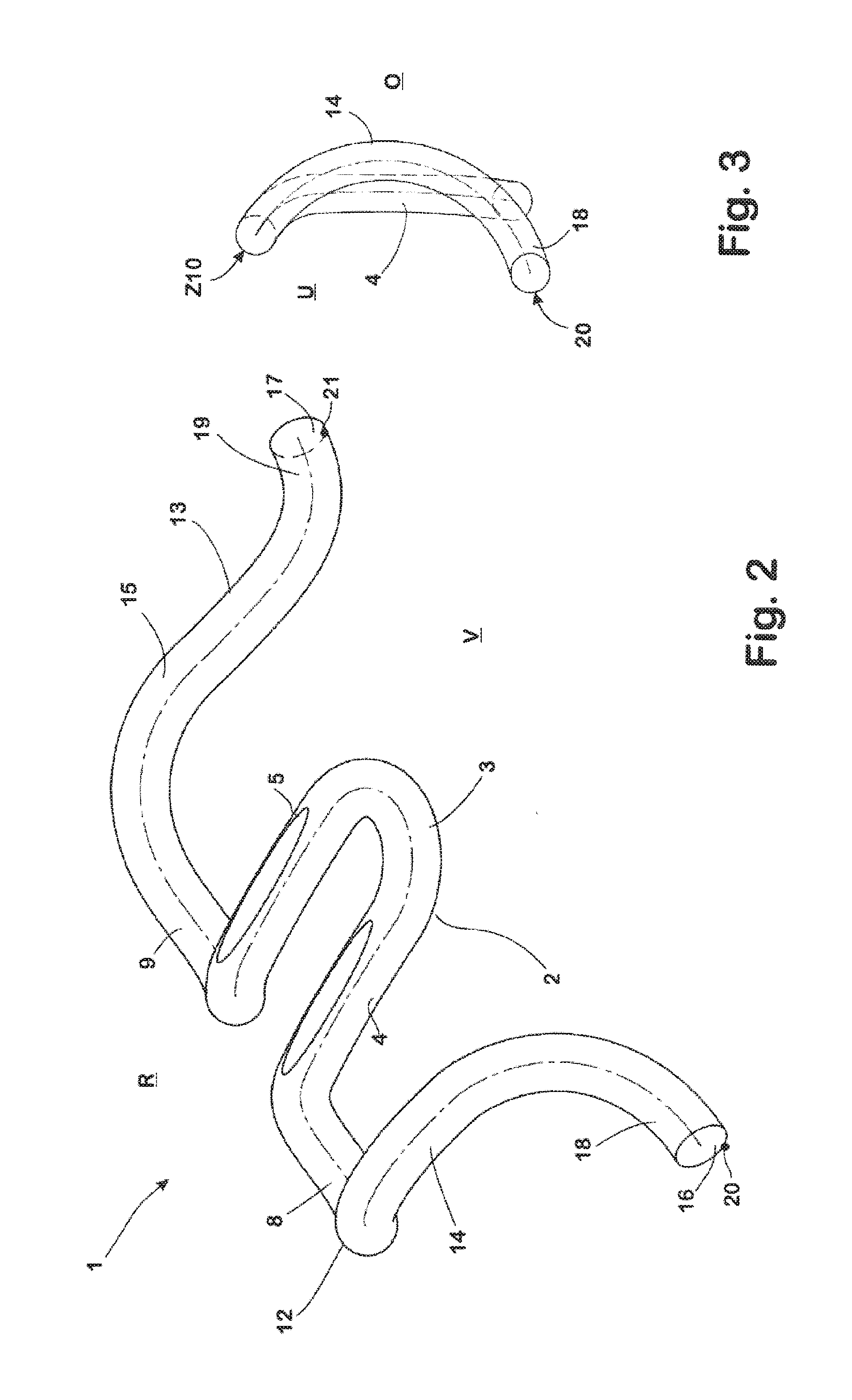
[0053] FIG. 2 shows the tension clamp according to FIG. 1 in a perspective view from its front side;
[0054] FIG. 3 shows the tension clamp according to FIGS. 1 and 2 in a side view;
[0055] FIG. 4 shows a guide plate with a conventional tension clamp arranged thereon in a perspective view from behind;
[0056] FIG. 5 shows the guide plate from FIG. 4 in a perspective view from the front.
[0057] The tension clamp 1 according to the invention, shown in FIGS. 1-3, bent in one piece from a spring wire with a circular cross section, has a U-shaped middle section 2 with a curved base section 3 associated with the front side V of the tension clamp and legs 4, 5, having a straight form, connected thereon. On the upper side of the legs 4, 5 of the middle section 2 associated with the upper side O of the tension clamp 1, flattened contact surfaces 6, 7 are provided, on which during use a sleeper screw (not shown here) is seated by means of its screw head, serving as a tension element for tensioning the tension clamp 1.
[0058] At their ends facing away from the base section 3, and pointing to the rear side R of the tension clamp 1, the legs 4, 5 of the middle section 2 merge respectively into a torsion section 8, 9 of the tension clamp 1. The torsion sections 8, 9 are respectively bent in the direction of the underside U of the tension clamp 1 and lead laterally outward away from the respectively associated leg 4, 5. On their underside, the torsion sections 8, 9 respectively have a support zone 10, 11, by means of which they are seated during use on a support surface of a guide plate.
[0059] At the end of the torsion sections 8, 9, respectively facing away from the middle section 2, a supporting arm 12, 13 is respectively connected. In the region of their spring sections 14, 15, the supporting arms 12, 13 are designed to be curved in an arc-like manner respectively in the direction of the upper side O of the tension clamp 1, and extend starting from the respective torsion section 8, 9 in the direction of the front side V of the tension clamp 1. Thus, they are aligned such that, seen in plan view from above (FIG. 1), the distance of the supporting arms 12, 13, measured parallel to the connecting lines G between the centres Z10, Z11 of the support zones 10, 11, increases starting respectively from the torsion sections 8, 9.
[0060] At their free ends 16, 17, the supporting arms 12, 13 respectively end in a support section 18, 19, connecting on their respective spring section 14, 15, by means of which the supporting arm 12, 13 in the operative condition is seated on the rail (not shown here) to be fastened in the respective rail fastening point. On the underside of the support sections 18, 19 associated with the underside U of the tension clamp 1, punctiform support zones 20, 21 are respectively formed thereto on the ends 16, 17 of the supporting arms 12, 13.
[0061] The support sections 18, 19 are formed pointing outwards from the middle section 2 in a continuous curve starting from the respective spring section 14, 15, so that they conform tangentially to a straight line aligned parallel to the connecting line G. The length of the supporting arms 12, 13 is dimensioned so that the punctiform support zones 20, 21, when seen in plan view from above (FIG. 1), are located in front of the base section 3 of the middle section 2 in the direction of the front side V of the tension clamp 1.
[0062] Due to the outward-pointing arrangement of the support sections 18, 19 and the punctiform support zones 20, 21 of the supporting arms 12, 13 located correspondingly laterally outwards, the connecting lines G1, G2, which on the one hand (connecting line G1) connect the centre Z10 of the support zone 10 of the torsion section 8 with the punctiform support zone 20 of the supporting arm 12 connected to the torsion section 8, said support zone thus itself representing the centre, and which on the on the other hand (connecting line G2) connect the centre Z11 of the support zone 11 of the torsion section 9 with the punctiform support zone 21 of the supporting arm 13 connected to the torsion section 9, said support zone thus likewise itself representing the centre, are arranged at an acute angle .beta.1 with respect to the axis of symmetry S of the tension clamp 1 and comprise an angle .beta.2 of approx. 70.degree. therebetween. Accordingly, when seen in plan view from above (FIG. 1), they intersect in a point of intersection SG located behind the rear side R of the tension clamp 1.
[0063] The distance AS, measured parallel to the axis of symmetry S, between the punctiform support zones 20, 21 of the supporting arms 12, 13, said support zones themselves forming the centre, on the one hand and the intersection SG on the other hand corresponds to approx. 1.5 times the distance AG, also measured parallel to the axis of symmetry S, of the punctiform support zones 20, 21 from the centres Z10, Z11 of the support zones 10, 11 of the torsion sections 8, 9. In practice, the distance AG can, for example, be approx. 100 mm and the distance AS approx. 150 mm, wherein the distance AS can be varied in the range of, for example, 130 mm to 170 mm, if this is expedient in terms of setting the natural frequencies or due to structural conditions.
[0064] Practical tests have shown that the tension clamp 1 has natural frequencies of at least 50% higher compared with a conventionally shaped tension clamp 101 shown in FIGS. 4 and 5. These are so high that even under unfavourable conditions of use, as may be the case for example in tunnels or on bridges, there is no excitation of the tension clamp 1 in the range of its natural frequencies.
[0065] The tension clamp 101 shown in FIGS. 4 and 5, arranged on a guide plate 100, has a U-shaped middle section 102 with legs extending parallel to each other, which merge respectively into a torsion section 108, 109 leading laterally outwards from the middle section 102 and bent towards the underside U of the tension clamp 101. The torsion sections 108, 109 also respectively have a support zone on their underside, with which they are seated on the guide plate 100 during use.
[0066] Thus a supporting arm 112, 113 is also respectively connected to its spring section 114, 115, curved upwards in an arc-like manner, on the torsion sections 108, 109. In contrast to the tension clamp 1 according to the invention, however, in the case of the tension clamp 101, the support sections 118, 119 of the tension clamp 101 ending at the free ends 116, 117 of the supporting arms 112, 113 are bent in the direction of the middle section 102, so that the ends 116, 117 of the tension clamp 101 directed towards one another and the connecting lines G1', G2', which respectively interconnect the punctiform support zones of the supporting arms 112, 113 to the centre Z110, Z111 of the support zones on the respective associated torsion section 108, 109, are aligned parallel to the axis of symmetry S' of the tension clamp 101.
[0067] In the case of the conventionally shaped tension clamp 101, in order to prevent damage as a result of excessive vibration movements as a result of excitation in the natural frequency range, stops 126, 127 are provided on the support surface 125, which is configured on the upper side of the guide plate 101 formed integrally of a plastic approved for this purpose, said stops being formed in the manner of supports. The stops 126, 127 are arranged in the region of the greatest height of the respective spring section 114, 115 of the tension clamp 101 and carry at their free frontal end respectively a U-shaped receptacle 128, 129, whose dimensions are proportioned so that the respective spring section 114, 115 is seated positively in the respective receptacle 128, 129, in the event that it comes into contact with the associated stop 126, 127. In order to dampen the contact, the receptacle is designed with a shock-absorbing material. The height position of the receptacles 128, 129 is selected to be such that the spring sections 114, 115 can perform the elastic movements required during normal operation, but are supported in the receptacles 128, 129 in the event of an excessive excitation exceeding those movements which are to be expected during normal operation.
[0068] With the support zones Z110, Z111 provided in the region of their torsion sections 108, 109, the tension clamp 101 is seated respectively in a depression 130, 131 formed in the support surface 125 of the guide plate 100. The depressions 130, 131 are designed in elevations 132, 133 formed on the contact surface 125. Their size, thickness and height is designed so that the arc length BL, which comprises a contact between the respective torsion section 108, 109 and the guide plate 100, is substantially greater than the approximately punctiform contact, which would be between the torsion sections 108, 109, if this were to be supported on a level support surface. The purpose of the depressions 130, 131 being configured in the elevations 132, 133 is that the position of the torsion sections 108, 109 is the same with respect to the support surface 125 as in the case of a support on a flat support surface 125, despite their being seated in the depressions 130, 131. The depressions 130, 131 are also designed with a suitable damping material to dampen the vibrations of the tension clamp 101.
REFERENCE NUMERALS
[0069] 1 Tension clamp [0070] 2 Middle section of the tension clamp 1 [0071] 3 Base section of the middle section 2 [0072] 4, 5 Legs of the middle section 2 [0073] 6, 7 Contact surfaces of the legs 4, 5 [0074] 8, 9 Torsion sections of the tension clamp 1 [0075] 10, 11 Support zones of the torsion sections 8, 9 [0076] 12, 13 Supporting arms of the tension clamp 1 [0077] 14, 15 Spring sections of the supporting arms 12, 13 [0078] 16, 17 Free ends of the supporting arms 12, 13 [0079] 18, 19 Support sections of the supporting arms 12, 13 [0080] 20,21 Punctiform support zones (=centre of the support zones 20, 21) [0081] G, G1, G2 Connecting lines [0082] Z10, Z11 Centres of the support zones 10, 11 [0083] .beta.1, .beta.2 Angles [0084] S Axis of symmetry of the tension clamp 1 [0085] 100 Guide plate [0086] 101 Tension clamp [0087] 102 U-shaped middle section of the tension clamp 101 [0088] 108, 109 Torsion sections the tension clamp 101 [0089] 112, 113 Supporting arm of the tension clamp 101 [0090] 114, 115 Spring sections of the supporting arms 112, 113 [0091] 116, 117 Free ends of the supporting arms 112, 113 [0092] 118, 119 Support sections of the tension clamp 101 [0093] 125 Support surface of the guide plate 100 [0094] 126, 127 Stops [0095] 128, 129 U-shaped receptacles (=seat) [0096] 130, 131 Depressions [0097] 132, 133 Elevations [0098] BL Arc length over which there is contact between the respective torsion section 108, 109 and the guide plate 100 [0099] G1', G2' Connecting lines [0100] Z110, Z111 Centre of the support zones of the torsion sections 108, 109 [0101] S' Axis of symmetry of the tension clamp 101 [0102] AG, AS Distances [0103] O Upper side of the tension clamps 1, 101 [0104] U Underside of the tension clamp 1, 101 [0105] R Rear side of the tension clamp 1, 101 [0106] SG point of intersection [0107] V Front side of the tension clamp 1, 101
* * * * *
References
D00000
D00001
D00002
D00003
XML
uspto.report is an independent third-party trademark research tool that is not affiliated, endorsed, or sponsored by the United States Patent and Trademark Office (USPTO) or any other governmental organization. The information provided by uspto.report is based on publicly available data at the time of writing and is intended for informational purposes only.
While we strive to provide accurate and up-to-date information, we do not guarantee the accuracy, completeness, reliability, or suitability of the information displayed on this site. The use of this site is at your own risk. Any reliance you place on such information is therefore strictly at your own risk.
All official trademark data, including owner information, should be verified by visiting the official USPTO website at www.uspto.gov. This site is not intended to replace professional legal advice and should not be used as a substitute for consulting with a legal professional who is knowledgeable about trademark law.