Guide Insert And Saw Blade Guide For A Bandsaw
EWERS; Christoph ; et al.
U.S. patent application number 16/356311 was filed with the patent office on 2019-09-19 for guide insert and saw blade guide for a bandsaw. This patent application is currently assigned to FREUND Maschinenfabrik GmbH & Co. KG. The applicant listed for this patent is FREUND Maschinenfabrik GmbH & Co. KG. Invention is credited to Christoph EWERS, Robert FREUND.
| Application Number | 20190283156 16/356311 |
| Document ID | / |
| Family ID | 67774748 |
| Filed Date | 2019-09-19 |
| United States Patent Application | 20190283156 |
| Kind Code | A1 |
| EWERS; Christoph ; et al. | September 19, 2019 |
GUIDE INSERT AND SAW BLADE GUIDE FOR A BANDSAW
Abstract
A guide insert for a saw blade guide for guiding a saw blade, including at least two blade guiding elements held in the guide insert, at least one pair of side blade guiding elements disposed in parallel and at the same height being accommodated in the guide insert, a slot for laterally guiding the saw blade being formed between a first side blade guiding element and a second side blade guiding element in a use position, the blade guiding elements having a rotationally symmetrical shape with respect to an axis of symmetry, including a cylindrical friction surface, the blade guiding elements each being held clamped in a cylindrical recess of the guide insert in a force-fitting and/or form-fitting manner via a loosenable clamp in the use position, and the blade guiding elements being able to be placed from a first rotational position into other rotational positions.
| Inventors: | EWERS; Christoph; (Willebadessen, DE) ; FREUND; Robert; (Paderborn, DE) | ||||||||||
| Applicant: |
|
||||||||||
|---|---|---|---|---|---|---|---|---|---|---|---|
| Assignee: | FREUND Maschinenfabrik GmbH &
Co. KG Paderborn DE |
||||||||||
| Family ID: | 67774748 | ||||||||||
| Appl. No.: | 16/356311 | ||||||||||
| Filed: | March 18, 2019 |
| Current U.S. Class: | 1/1 |
| Current CPC Class: | B23D 55/082 20130101 |
| International Class: | B23D 55/08 20060101 B23D055/08 |
Foreign Application Data
| Date | Code | Application Number |
|---|---|---|
| Mar 16, 2018 | DE | 10 2018 106 139.0 |
| Feb 26, 2019 | DE | 10 2019 104 810.9 |
| Mar 8, 2019 | DE | 10 2019 105 959.3 |
Claims
1. A guide insert for a saw blade guide for guiding a saw blade, the guide insert comprising: at least two blade guiding elements held in the guide insert; at least one pair of side blade guiding elements disposed in parallel and at a same height being accommodated in the guide insert; and a slot for laterally guiding the saw blade, the slot being formed between a first side blade guiding element and a second side blade guiding element in a use position, the blade guiding elements having a rotationally symmetrical shape with respect to an axis of symmetry, including a cylindrical friction surface, the blade guiding elements each being held clamped in a cylindrical recess of the guide insert in a force-fitting and/or form-fitting manner via a loosenable clamp in the use position, and the blade guiding elements being able to be placed from a first rotational position into other rotational positions by loosening the clamp and by rotation around the axis of symmetry.
2. The guide insert according to claim 1, wherein the blade guiding elements are manufactured from a hard ceramic and/or the friction surfaces of the blade guiding elements have a coating made from a hard ceramic.
3. The guide insert according to claim 1, wherein the blade guiding elements have a conically tapering frustoconical section opposite the friction surface.
4. The guide insert according to claim 3, wherein, in the use position, the clamp presses onto the frustoconical sections of the blade guiding elements with a clamping force in the use position.
5. The guide insert according to claim 1, wherein the clamp is at least one screw, which is screwed into the guide insert from the outside and is a cone screw.
6. The guide insert according to claim 1, wherein an upper blade guiding element is positioned orthogonally to the cutting plane in the use position, and is held in the guide insert for guiding a toothless blade back of the saw blade, the blade back of the saw blade only temporarily resting on the friction surface of the upper blade guiding element in the use position.
7. The guide insert according to claim 1, wherein all blade guiding elements have the same shape, the first side blade guiding element being replaceable with the second side blade guiding element and/or with the upper blade guiding element and vice versa.
8. The guide insert according to claim 1, wherein the side blade guiding elements are held in the guide insert in the use position in such a way that a middle blade area of the saw blade is guided between the friction surfaces of the side blade guiding elements, the blade back of the saw blade and/or a blade toothing of the saw blade projecting over the side blade guiding elements.
9. The guide insert according to claim 2, wherein the hard ceramic has a Vickers hardness greater than 1600 VH 0.5, and/or the hard ceramic is an aluminum oxide and/or a silicon nitride.
10. A saw blade guide for guiding a saw blade of a bandsaw power tool, comprising: a guide block; and a guide insert, the guide insert being removably held in a mounting position in the guide block, the guide block including a hinge-shaped, pivotable locking bolt in the guide insert for the locking thereof, and the guide insert being designed as a guide insert according to claim 1.
11. The saw blade guide according to claim 10, wherein a lower edge of the guide insert engages with a recess of the locking bolt, which is formed in correspondence with the guide insert, at least in sections, for locking the guide insert in the guide block in a locking position, the locking bolt being fixed in the locking position in a form-fitting manner.
12. The saw blade guide according to claim 10, wherein a spring pin provided on the upper side of the guide insert projects into a correspondingly shaped pin recess of the guide block acting against at least one spring for removing the guide insert from the guide block, the guide insert being inserted deeper into the guide block along the insertion direction, and the locking bolt being pivotable out of the locking position into an unlocking position.
Description
[0001] This nonprovisional application claims priority under 35 U.S.C. .sctn. 119(a) to German Patent Application No. 10 2018 106 139.0, which was filed on Mar. 16, 2018, German Patent Application No. 10 2019 104 810.9, which was filed on Feb. 26, 2019, and German Patent Application No. 10 2019 105 959.3, which was filed on Mar. 8, 2019, and all of which are herein incorporated by reference.
BACKGROUND OF THE INVENTION
Field of the Invention
[0002] The present invention relates to a guide insert for a saw blade guide for guiding a saw blade, including at least two blade guide elements held in the guide insert. The invention also relates to a saw blade guide for guiding a saw blade of a bandsaw power tool.
Description of the Background Art
[0003] Bandsaw power tools are used in different specific embodiments. Hand-guided bandsaw power tools are used in many different areas, for example in the meat industry for cutting up animal carcasses. Strict hygienic requirements for processing meat must be observed here, and downtimes due to a wear-induced power tool failure must be minimized, since they result in high financial losses. In these bandsaw power tools, a continuous saw blade is driven laterally around the circumference by two wheels. In the freely running part of the saw blade, the so-called cutting segment, the saw blade is guided by two guide blocks of a saw blade guide, which are provided at a distance from each other and expose the sawing area for the purpose of sawing the particular workpiece. The saw blade guide is provided for preventing or minimizing a warping and/or vibrating of the saw blade and is thus necessary for a high quality, straight sawing cut of the saw blade through the workpiece. To reach a desired cutting plane, the saw blade in the cutting segment may be rotated on the wheels by 90.degree. with respect to the rotational position. In the guide blocks of the saw blade guide, the saw blade is directed into the cutting plane before entering or leaving the workpiece to be sawed or it is directed back into the rotational position on the wheels from the cutting plane.
[0004] The guide blocks of saw blade guides of this type for a bandsaw power tool are usually fitted with blade guiding elements, which, according to the known teaching, are formed in the guide block as rigidly held sliding block bodies or as rotatably held rollers and along which the saw blade runs during operation. These blade guiding elements are usually manufactured from hard metal. During the operation of bandsaw power tools of this type, the saw blade and the blade guiding elements are subjected to increased wear due to a greatly increased friction and a greatly increased heat development associated therewith in the area of the sliding contact surfaces or friction surfaces between the blade guiding elements and the saw blade. This causes a reduction in the guiding properties of the saw blade guide and an increased wear on the saw blade and the blade guiding elements, which results in a premature replacement of these wearing parts and thus a failure of the bandsaw power tool, which incurs costs. A martensitic hardening, for example, may also be initiated in a blade material of the saw blade, which may embrittle the saw blade and whereby hairline cracks in the saw blade may form, due to which the saw blade finally cracks and may result in a failure of the bandsaw power tool.
[0005] DE 10 2017 109 230 A1, which corresponds to US 2017/0320149, and which is incorporated herein by reference, discloses a blade guiding element for a saw blade guide for a saw blade, which includes a cutting segment of a bandsaw power tool, which is rotated by 90.degree. with respect to a rotational position. The blade guiding element is implemented in the form of a symmetrical prism-shaped sliding block having two planar friction surfaces. Compared to rotating blade guiding elements rolling on the saw blade, a saw blade guide having blade guiding elements in the form of sliding blocks facilitates a less noisy operation of the bandsaw power tool. The sliding block is manufactured from a hard ceramic and ensures a longer lifespan for the sliding block as well as for the saw blade, compared to a sliding block made from hard metal. In this blade guide having sliding blocks held rigidly in the guide blocks, regular wear of the sliding block material occurs during the operation of the bandsaw power tool, as a result of increased friction and the increased heat development associated therewith locally on the planar friction surfaces and on the edges of the friction surfaces between the sliding blocks and the saw blade sliding along them. The sliding blocks may be rotated by 180.degree., whereby a first friction surface is brought into engagement with a non-worn second friction surface after wear. However, to replace the friction surfaces or a wear-induced replacement of these sliding blocks, the latter must be removed from a guide plate in a guide carriage, on which they are held via two screw connections inserted through bores in the sliding blocks, using a retooling tool, such as a screwdriver. This retooling operation is comparatively complex and also involves the risk that "losable" parts, such as the aforementioned screw connections, may enter the workpieces. This is always to be avoided when processing food, for example in the meat-processing industry.
SUMMARY OF THE INVENTION
[0006] It is therefore an object of the present invention to provide a guide insert for a saw blade guide and a saw blade guide in such a way that the saw blade guide is faster and easier to repair, and a prolonged lifespan of the blade guiding elements and the saw blade of the bandsaw power tool is ensured.
[0007] Accordingly, in an exemplary embodiment, at least one pair of side blade guiding elements is accommodated in parallel and at the same height in the guide insert. In one use position, a slot for laterally guiding the saw blade is formed between a first side blade guiding element and a second side blade guiding element. The blade guiding elements have a rotationally symmetrical shape with respect to an axis of symmetry, including a cylindrical friction surface. In the use position, the blade guiding elements are each held via a loosenable clamp in a cylindrical recess in a force-fitting and/or form-fitting manner and clamped against rotation around the axis of symmetry. By loosening the clamp, the blade guiding elements may be placed from a first rotational position into other rotational positions by rotation around the axis of symmetry.
[0008] The special advantage of the invention is in the use of rotationally symmetrical blade guiding elements having cylindrical friction surfaces. Blade guiding elements of this type are cost-effective to manufacture with little manufacturing complexity and may be placed from a first rotational position into a large number of additional rotational positions with comparatively little effort by rotating them around their axis of symmetry at a predetermined angle. In this respect, more usable rotational positions or defined contact areas of the friction surface may be implemented than is the case in known sliding block approaches having cuboid or cubical blade guiding elements with two, four or a maximum of six mounting positions. A complete unmounting and re-mounting of the rotationally symmetrical blade guiding elements during the rotation thereof is not absolutely necessary.
[0009] In addition, due to the cylindrical shape of the friction surfaces of the rotationally symmetrical blade guiding elements, torsion forces of the saw blade may be broadly absorbed during the 90.degree. pivoting of the saw blade from the rotational position on the wheels into the cutting plane spanned by the sawing area or cutting segment. This reduces the wear or abrasion of the side blade guiding elements as a result of the 90.degree. pivoting of the saw blade.
[0010] A core idea of the invention is thus to use easily replaceable and, in particular, long-lived rotationally symmetrical blade guiding elements for guiding the saw blade.
[0011] The blade guiding elements can be manufactured from a hard ceramic or have friction surfaces with a coating made from a hard ceramic. Blade guiding elements made from ceramic generally have an above-average resistance to temperature fluctuations and a very high fracture toughness, whereby they are insensitive to jolts and impacts. They also have good sliding properties, whereby they produce a reduced friction effect and this a reduced heat development as well as a reduced noise level during operation. As a result, hard ceramic blade guiding elements of this type have a reduced wear and a prolonged lifespan in and of themselves as well as for the saw blade guided along them during operation. Costly down times of bandsaw power tools may thus be significantly reduced.
[0012] The hard ceramic can have a Vickers hardness greater than 1600 VH 0.5 and/or is, for example, an aluminum oxide and/or a silicon nitride. Hard ceramics of this type have a sufficient hardness and wear resistance for operation on a saw blade sliding along them.
[0013] The blade guiding elements can have a conically tapering, frustoconical section opposite the friction surface. In the use position of the blade guiding elements provided in pairs in the guide block, the frustoconical section forms an enlarged tapering gap, which greatly simplifies the insertion of the saw blade into the guide insert or into the guide block and thus the mounting effort.
[0014] The clamp can press down on the frustoconical sections of the blade guiding elements with a clamping force in the use position. Accordingly, a premature wear or an abrasion of the friction surfaces due to the clamp is avoided.
[0015] The clamp can be, for example, screws and preferably cone screws, which may be screwed into the guide insert from the outside.
[0016] An upper blade guiding element, preferably positioned perpendicularly to the cutting plane in the use position, is held in the guide insert for guiding a toothless blade back of the saw blade, the blade back of the saw blade normally not abutting the friction surface of the upper blade guiding element in the use position. Contact with the upper blade guiding element occurs only if a strong pressure is applied to the saw blade, for example when using a blunt saw blade. A guiding of the blade back in this manner generally prevents the saw blade from pressing through the side blade guiding elements during operation in the case of a rotating saw blade and absorbs forces and the vibrations along the cutting area in the cutting segment, thus relieving the side blade guiding elements. This guidance of the blade back thus ensures an improved cutting pattern or facilitates a more forceful and thus faster cut through the workpiece during the operation of the bandsaw power tool.
[0017] The blade guiding elements can have the same shape, the first side blade guiding element being replaceable with the second side blade guiding element and/or with the upper blade guiding element and vice versa. Manufacturing and maintenance costs may be reduced by this use of equivalent parts of the blade guiding elements.
[0018] The side blade guiding elements can be held in the guide insert in the use position in such a way that a middle blade area of the saw blade is guided between the friction surfaces of the side blade guiding elements, the blade back of the saw blade and/or a blade toothing of the saw blade projecting over the side blade guiding elements. As a result, the side blade guiding elements are provided with a sufficiently short design in such a way that the saw blade slides thereon only in its middle area, and thermal stresses resulting from the friction effect are reduced as a whole and, in particular, in the area of the blade toothing and the blade back of the saw blade. A reduced wear and an increased lifespan of the saw blade and the side blade guiding elements may be implemented thereby.
[0019] The saw blade guide can include a guide block, in which a guide insert is removably held in a mounting position, the guide block having a hinge-shaped, pivotable locking bolt for locking the guide insert therein.
[0020] A lower edge of the guide insert can project into a recess of the locking bolt, which corresponds to the guide insert at least in sections, for the purpose of locking the guide insert in the guide block in a locking position, the locking bolt being fixed in the locking position in a form-fitting manner.
[0021] A spring pin provided on an upper side of the guide insert engages with a correspondingly shaped pin recess of the guide block, acting against at least one spring, for the purpose of removing the guide insert from the guide block, the guide insert being inserted deeper into the guide block along the insertion direction, and the locking bolt being pivotable out of the locking position into an unlocking position. In this way, the guide insert may be quickly removed from the guide block with easy movements and without the risk of losable parts if the blade guiding elements become worn, either to place the locally worn friction surface of the blade guiding elements into a different rotational position or to replace the guide insert with a guide insert having non-worn blade guiding elements. Wear-induced down times of bandsaw power tools having a saw blade guide of this type or retooling times for exchanging the worn blade guiding elements are thus greatly reduced, whereby the bandsaw power tools have a greater profitability. In addition, there is no risk of the losable parts entering workpieces when replacing the guide insert or the blade guiding elements, which must necessarily be avoided, in particular when processing food, such as in the meat-processing industry.
[0022] Guide inserts can be provided in the saw blade guide.
[0023] Further scope of applicability of the present invention will become apparent from the detailed description given hereinafter. However, it should be understood that the detailed description and specific examples, while indicating preferred embodiments of the invention, are given by way of illustration only, since various changes, combinations, and modifications within the spirit and scope of the invention will become apparent to those skilled in the art from this detailed description.
BRIEF DESCRIPTION OF THE DRAWINGS
[0024] The present invention will become more fully understood from the detailed description given hereinbelow and the accompanying drawings which are given by way of illustration only, and thus, are not limitive of the present invention, and wherein:
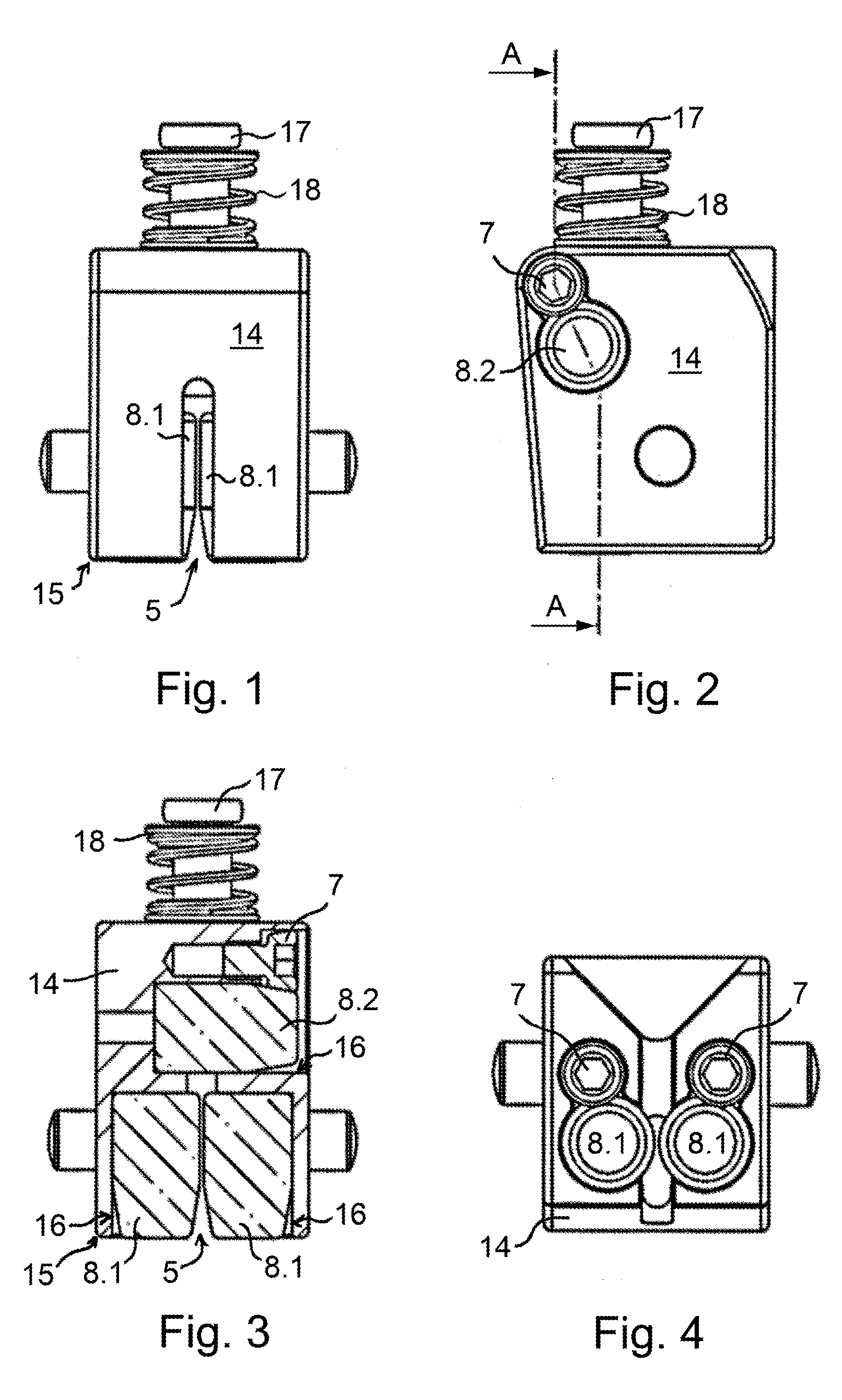
[0025] FIG. 1 shows a front view of a guide insert according to the invention, including blade guiding elements for guiding a saw blade;
[0026] FIG. 2 shows a side view of the guide insert according to FIG. 1;
[0027] FIG. 3 shows section A-A of the guide insert according to FIG. 2;
[0028] FIG. 4 shows the guide insert according to FIG. 1, viewed from below;
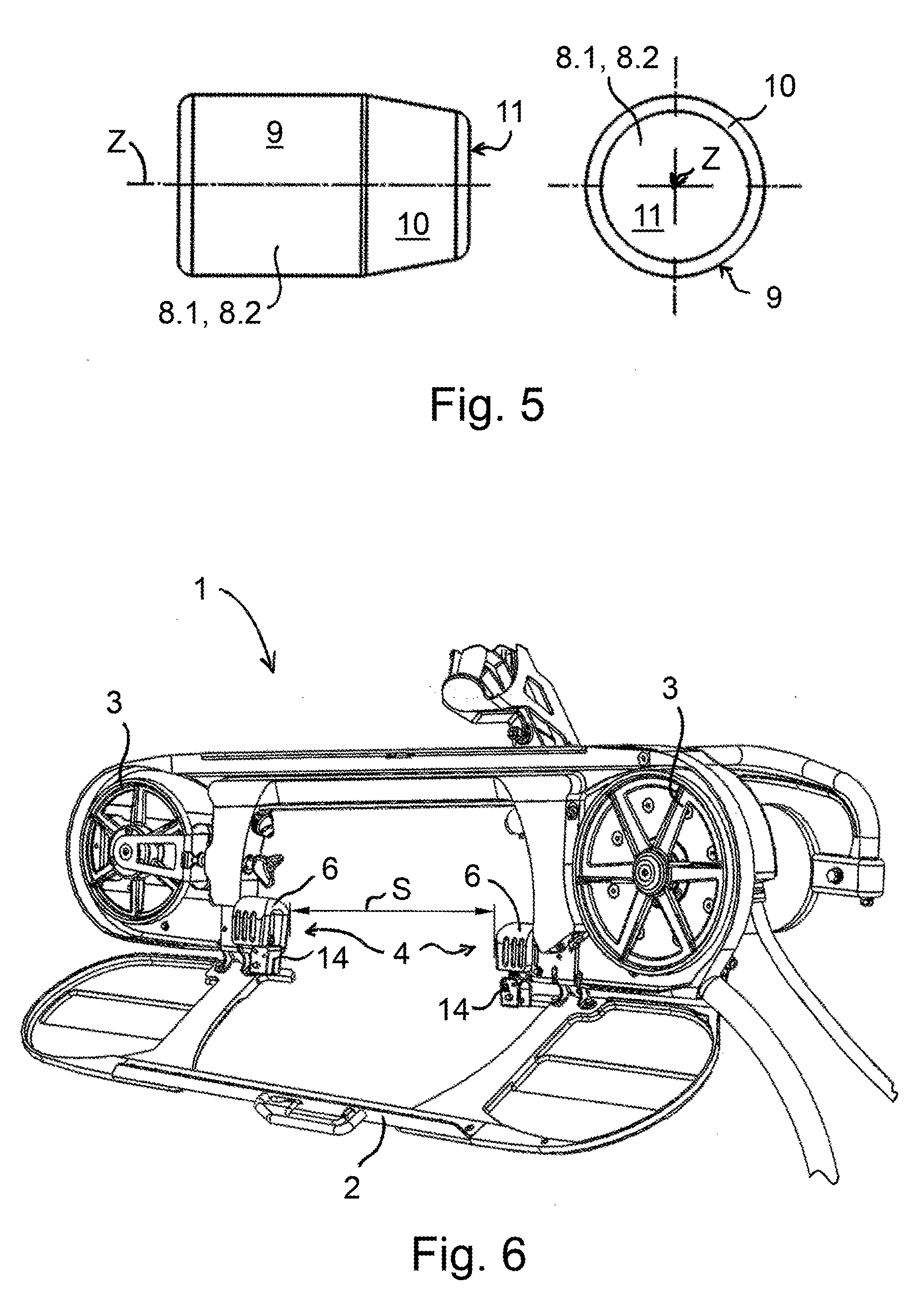
[0029] FIG. 5 shows a blade guiding element of the guide insert according to FIG. 1; a side view is on the left; an end face view is on the right;
[0030] FIG. 6 shows a perspective view of a hand-guided bandsaw power tool, including a housing flipped into an open position, without the saw blade and with two saw blade guides according to the invention, including guide inserts removed from guide blocks;
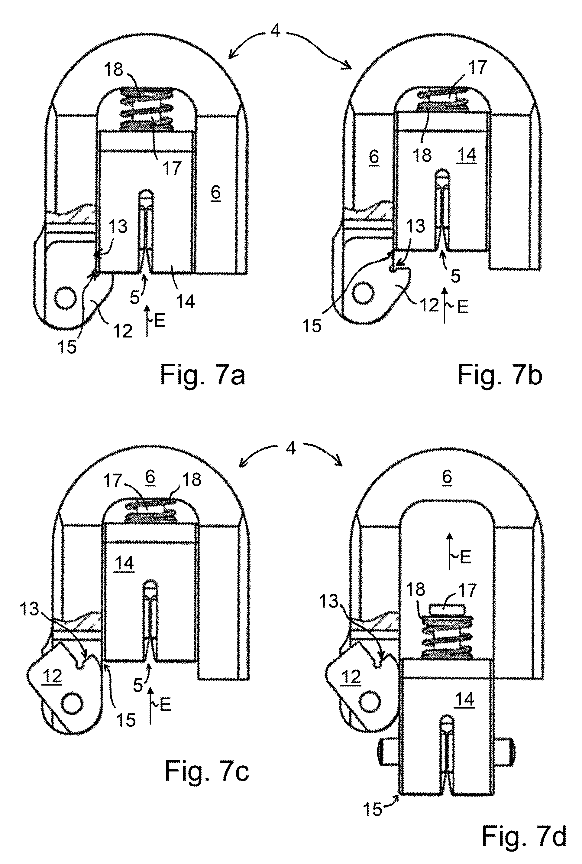
[0031] FIG. 7a shows a front view of a saw blade guide according to the invention according to FIG. 6, including a guide block having a locking bolt in a locking position and having a guide insert held in the guide block, the guide block being cut way in the area of the locking bolt at least in sections;
[0032] FIG. 7b shows the saw blade guide according to FIG. 7a with the guide insert in an intermediate position inserted deeper into the guide block against a spring;
[0033] FIG. 7c shows the saw blade guide according to FIG. 7b, including the locking bolt in an unlocking position; and
[0034] FIG. 7d shows the saw blade guide according to FIG. 7c, including the guide insert removed at least in sections.
DETAILED DESCRIPTION
[0035] FIG. 1 through FIG. 4 show an exemplary embodiment of a guide insert 14 according to the invention, including blade guiding elements 8.1, 8.2 held or accommodated therein for guiding a saw blade, which is not illustrated.
[0036] A front view of guide insert 14 in FIG. 1 illustrates the position of side blade guiding elements 8.1 disposed in pairs in guide insert 14. Side blade guiding elements 8.1 are each held at an identical height as well as in parallel in a cylindrical recess 16 of guide insert 14. Cuboid guide insert 14 in this exemplary embodiment has a slot-shaped opening emptying into an underside, into which side blade guiding elements 8.1 slightly project horizontally. Side blade guiding elements 8.1 are positioned at a distance from each other in guide insert 14, so that a gap 5 forms between them, and the saw blade is able to slide and be guided along between a first side blade guiding element 8.1 and a second side blade guiding element 8.1. To simplify the mounting or insertion of the saw blade into guide insert 14 by forming an enlarged, conical gap 5, side blade guiding elements 8.1 have a tapering frustoconical section 10 and are inserted into guide insert 14 in such a way that frustoconical section 10 faces downward in each case.
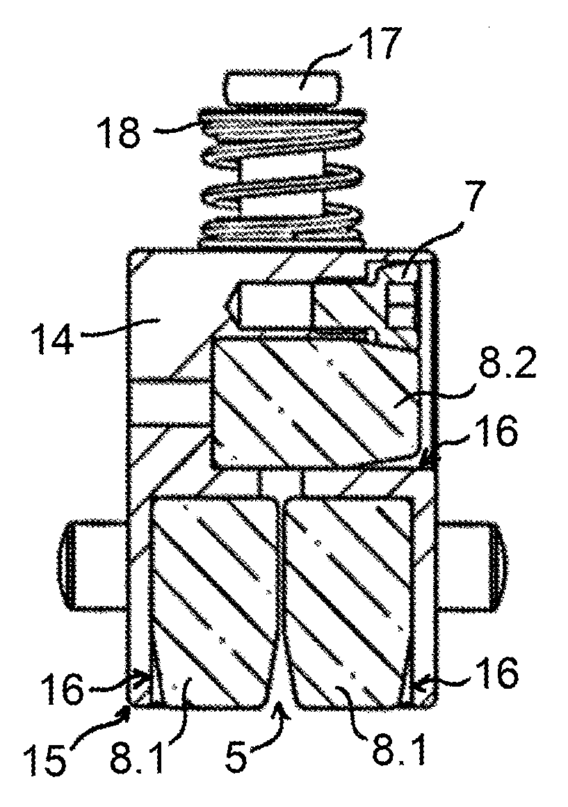
[0037] FIG. 2 shows a side view of guide insert 14 according to claim 1. In guide insert 14, above side blade guiding element 8.1 accommodated therein, a blade guiding element 8.2 having the same shape is provided, which is used to guide a toothless blade back of the saw blade. In the use position, the blade back does not permanently rest on friction surface 9 of upper blade guiding element 8.2. If an increased pressure is applied to the saw blade, however, the blade back slides along friction surface 9, so that upper blade guiding element 8.2 is also subjected to an operation-induced wear. Upper blade guiding element 8.2 is clamped against a rotation around an axis of symmetry Z via a clamp 7, a cone screw in this exemplary embodiment, so that upper blade guiding element 8.2 is rigidly held in guide insert 14 during operation when a saw blade slides along it, and only a defined contact area of friction surface 9 becomes worn due to operation.
[0038] During the operation of guide insert 14 in a use position on a bandsaw tool 1, saw blade runs along the contact area of cylindrical friction surfaces 9 of blade guiding elements 8.1, 8.2. Due to this friction, an abrasion and a local heat development occur, or a thermal load on blade guiding elements 8.1, 8.2 and saw blade occurs, whereby the latter become increasingly worn as the number of operating hours rises. As the wear increases, the guiding accuracy and thus the cutting pattern become poorer in quality, so that blade guiding elements 8.1, 8.2 as well as the saw blade must be replaced at some point due to wear as the number of operating hours increases. To minimize costly down times, blade guiding elements 8.1, 8.2 should have the least possible wear or a preferably long lifespan. Blade guiding elements 8.1, 8.2 are preferably manufactured for this purpose from a durable, hard and temperature-resistant material, preferably from a hard ceramic. To reduce the wear on blade guiding elements 8.1, 8.2 and the saw blade, which occurs due to operation as a result of thermal loads, side blade guiding elements 8.1, in particular, are dimensioned to be sufficiently short, the saw blade being in contact therewith only in a middle saw area, and the blade back and a blade toothing of the saw blade projecting over side blade guiding elements 8.1.
[0039] FIG. 3 shows section A-A according to FIG. 2. The position of blade guiding elements 8.1, 8.2 in guide insert 14 is clarified therein. Cylindrical friction surface 9 of upper blade guiding element 8.2 is preferably provided in the middle above gap 5, which is formed between side blade guiding elements 8.1. Accordingly, the saw blade runs along friction surfaces 9 of blade guiding elements 8.1, 8.2 during operation. The cone screw or clamp 7 applies a clamping force into frustoconical section 10 of upper blade guiding element 8.2. This ensures that friction surface 9 of upper blade guiding element 8.2 does not become prematurely worn or damaged due to clamp 7, which would result in negative effects on the guiding accuracy and the quality of the cutting pattern.
[0040] A view of guide insert 14 from below in FIG. 4 shows end faces 11 of side blade guiding elements 8.1. Similarly to upper blade guiding element 8.2, these are each clamped against a rotation around their axis of symmetry Z with the aid of a clamp 7 in the form of a cone screw. Side blade guiding elements 8.1 are designed similarly to upper blade guiding element 8.2.
[0041] One of blade guiding elements 8.1, 8.2 held in guide insert 6 according to the invention as shown in FIG. 1 through FIG. 4 is illustrated on its own in FIG. 5. Blade guiding element 8.1, 8.2 is shown in a side view on the left, and a front-end view of end face 11 is illustrated on the right. Blade guiding element 8.1, 8.2 has a rotationally symmetrical shape with regard to axis of symmetry Z, including cylindrical friction surface 9 and including conically tapering frustoconical section 10 opposite friction surface 9. The rotationally symmetrical shape of blade guiding element 8.1, 8.2 makes to possible to place a contact area of friction surface 9, which has become worn as a result of the saw blade running along it during operation, from a first rotational position into another rotational position by rotation around axis of symmetry Z. The cylindrical shape of friction surface 9 permits a large number of rotational positions or usable contact areas, so that blade guiding elements 8.1, 8.2 may be used for a long time before they need to be removed from guide insert 14 and replaced. In each case, blade guiding element 8.1, 8.2 has rounded edges or radii on the end face to simplify handling and mounting in guide insert 14.
[0042] FIG. 6 shows an application example of an exemplary embodiment of a saw blade guide 4 according to the invention in a hand-guided bandsaw power tool 1. Bandsaw power tool 1 is shown in a perspective view, including a housing 2, which is flipped open for the sake of better understanding. A saw blade rotating over wheels 3 or driven by right wheel 3 is not illustrated in FIG. 6. Two saw blade guides 4 according to the invention are provided in bandsaw power tool 1, which are spaced a distance apart so that a free sawing area S opposite housing 2 is formed between them for the saw blade. Saw blade guides 4 each include a guide block 6 connected to housing 2 via a connector and a guide insert 14, insertable into guide block 6, as essential components. For this purpose, guide blocks 6 each have a U-shaped body, which is open in the downward direction, in such a way that guide inserts 14 may be inserted into guide blocks 6 from below.
[0043] Saw blade guide 4 according to FIG. 6 is illustrated on its own in a front view in each of FIGS. 7a through 7d. FIGS. 7a through 7d show different positions of the main components of saw blade guide 4, which set in when guide insert 14 is removed from guide block 6. To lock guide insert 14 therein, guide block 6 has a locking system, including a locking bolt 12. For the same of better understanding, guide block 6 is cut away, at least in sections, in the area of the locking system in FIGS. 7a through 7d. Locking bolt 12 is held on guide block 6, rotatable around a pivot. FIG. 7a shows guide insert 14 inserted into guide block 6, locking bolt 12 being held in a locking position, which prevents guide insert 14 from being pushed out of guide block 6. A square recess 13 engages in a form-fitting manner with a lower edge 15 and the surrounding area of guide insert 14. In this locking position, locking bolt 12 is unable to pivot due to the form fit created. To do this, guide insert 14 must be inserted deeper into guide block 6 along an insertion direction E in parallel to side blade guiding elements 8.1, as illustrated in FIG. 7b. For this purpose, guide block 6 has a pin recess, which is not illustrated and into which a spring pin 17 provided on the upper side of guide insert 14 operatively projects against a surrounding spring 18, preferably a spiral spring. In this intermediate position according to FIG. 7b, it is possible to pivot locking bolt 12 around its pivot out of the locking position into an unlocking position. FIG. 7c shows locking bolt 12, placed into the unlocking position with respect to saw blade guide 4 according to FIG. 7b. The unlocking position of locking bolt 12 makes it possible to remove guide insert 14 from guide block 6 against insertion direction E. This is sketched in FIG. 7d, where guide insert 14 is removed from guide block 6 at least in sections. An insertion of guide insert 14 into guide block 6 takes place accordingly in reverse order from the removal sketched over the course of FIGS. 7a through 7d. To linearly insert guide insert 14 into guide block 6, guide pins are provided on the side of guide insert 14, each of which is inserted in a form-fitting manner into a correspondingly shaped guide pin recess, which is not illustrated, in a side arm section of U-shaped guide block 6.
[0044] The invention is not limited to the illustrated specific embodiment of guide insert 14 according to the invention and saw blade guide 4 according to the invention. In particular, the exemplary embodiment of guide insert 14 according to the present invention shown in FIG. 1 through FIG. 7d is not limited to the use in the exemplary embodiment of guide block 6 of saw blade guide 4 according to the invention, which is illustrated in FIG. 6 through FIG. 7d. The same applies to the use of saw blade guide 4 according to the invention, which is illustrated in FIG. 6 through FIG. 7d and which is not limited to the use of bandsaw power tool 1 illustrated in FIG. 6. Instead, saw blade guide 4 may generally be also used in other types of devices or machines for guiding a saw blade.
[0045] Alternative specific embodiments for guide insert 14 and saw blade guide 4 are formed, while maintaining the invention, for example in that blade guiding elements 8.1, 8.2 have a rotationally symmetrical cylindrical shape without frustoconical section 10 with regard to axis of symmetry Z, blade guiding elements 8.1, 8.2 being able to have chamfers or radii on the end face. It is also conceivable that nozzle channels or nozzles are provided in guide insert 14 for cleaning or cooling blade guiding elements 8.1, 8.2 or saw blade with the aid of a fluid. A fluid suitable for this purpose is, for example, water. In an alternative specific embodiment of guide insert 14, upper blade guiding element 8.2 may have a different shape compared to side blade guiding elements 8.1 or not be provided in guide insert 14. Guide block 6 may be a component of housing 2 of bandsaw power tool 1 or be held thereon via connector, for example screw connections.
[0046] The invention being thus described, it will be obvious that the same may be varied in many ways. Such variations are not to be regarded as a departure from the spirit and scope of the invention, and all such modifications as would be obvious to one skilled in the art are to be included within the scope of the following claims
* * * * *
D00000
D00001
D00002
D00003
XML
uspto.report is an independent third-party trademark research tool that is not affiliated, endorsed, or sponsored by the United States Patent and Trademark Office (USPTO) or any other governmental organization. The information provided by uspto.report is based on publicly available data at the time of writing and is intended for informational purposes only.
While we strive to provide accurate and up-to-date information, we do not guarantee the accuracy, completeness, reliability, or suitability of the information displayed on this site. The use of this site is at your own risk. Any reliance you place on such information is therefore strictly at your own risk.
All official trademark data, including owner information, should be verified by visiting the official USPTO website at www.uspto.gov. This site is not intended to replace professional legal advice and should not be used as a substitute for consulting with a legal professional who is knowledgeable about trademark law.