Blade Clamp For Power Tool
Wyler; Andrew R.
U.S. patent application number 16/280439 was filed with the patent office on 2019-09-19 for blade clamp for power tool. The applicant listed for this patent is MILWAUKEE ELECTRIC TOOL CORPORATION. Invention is credited to Andrew R. Wyler.
| Application Number | 20190283155 16/280439 |
| Document ID | / |
| Family ID | 67903802 |
| Filed Date | 2019-09-19 |


| United States Patent Application | 20190283155 |
| Kind Code | A1 |
| Wyler; Andrew R. | September 19, 2019 |
BLADE CLAMP FOR POWER TOOL
Abstract
A blade clamp for use with a power tool having a reciprocating spindle. The blade clamp comprises a cover threaded to the spindle for relative axial movement thereto in response to rotation of the cover relative to the spindle, an ejector pin positioned within the spindle, and a spring coupling the cover and the spindle. The spring biases the cover toward a first rotational position relative to the spindle coinciding with a locked configuration of the blade clamp. The cover is rotatable against the bias of the spring toward a second rotational position relative to the spindle coinciding with an unlocked configuration of the blade clamp. In the unlocked configuration, the ejector pin maintains the cover in the second rotational position. In response to insertion of a blade into the spindle, the blade clamp is automatically adjustable from the unlocked configuration to the locked configuration.
| Inventors: | Wyler; Andrew R.; (Pewaukee, WI) | ||||||||||
| Applicant: |
|
||||||||||
|---|---|---|---|---|---|---|---|---|---|---|---|
| Family ID: | 67903802 | ||||||||||
| Appl. No.: | 16/280439 | ||||||||||
| Filed: | February 20, 2019 |
Related U.S. Patent Documents
| Application Number | Filing Date | Patent Number | ||
|---|---|---|---|---|
| 62643851 | Mar 16, 2018 | |||
| Current U.S. Class: | 1/1 |
| Current CPC Class: | B23D 49/162 20130101; B23D 51/10 20130101 |
| International Class: | B23D 51/10 20060101 B23D051/10; B23D 49/16 20060101 B23D049/16 |
Claims
1. A blade clamp for use with a power tool having a reciprocating spindle, the blade clamp comprising: a cover threaded to the spindle for relative axial movement thereto in response to rotation of the cover relative to the spindle; an ejector pin positioned within the spindle; and a spring coupling the cover and the spindle; wherein the spring biases the cover toward a first rotational position relative to the spindle coinciding with a locked configuration of the blade clamp, wherein the cover is rotatable against the bias of the spring toward a second rotational position relative to the spindle coinciding with an unlocked configuration of the blade clamp, wherein in the unlocked configuration, the ejector pin maintains the cover in the second rotational position, and wherein, in response to insertion of a blade into the spindle, the ejector pin disengages the cover, permitting the spring to rebound and rotate the cover from the second rotational position toward the first rotational position, thereby automatically adjusting the blade clamp from the unlocked configuration to the locked configuration.
2. The blade clamp of claim 1, wherein the cover includes a first slot, wherein the ejector pin includes a second slot, and wherein the blade is receivable within the blade clamp through the first slot and the second slot.
3. The blade clamp of claim 2, wherein in the unlocked configuration, the first slot and the second slot are rotationally aligned, and in the locked configuration, the first slot and the second slot are rotationally misaligned.
4. The blade clamp of claim 1, wherein the cover includes an inner surface in facing relationship with the spindle and a first attachment element defined at least partially by the inner surface, the first attachment element configured to cooperate with a second attachment element of the ejector pin to maintain the cover in the second rotational position, and wherein insertion of the blade into the spindle displaces the ejection pin, thereby disengaging the first attachment element from the second attachment element.
5. The blade clamp of claim 4, further comprising a second spring for biasing the second attachment element toward the first attachment element.
6. The blade clamp of claim 4, wherein the cover includes a face at a first end of the cover, and the inner surface extends axially relative to a longitudinal axis of the spindle from the face to a second end of the cover, wherein the first attachment element is positioned axially inward of the face at the first end and radially inward of the inner surface relative to the longitudinal axis.
7. The blade clamp of claim 1, further comprising a second spring coupling the spindle and the ejector pin, wherein the second spring biases the ejector pin toward the cover in the unlocked configuration and the locked configuration, and wherein the ejector pin is displaceable by the blade against the bias of the second spring.
8. The blade clamp of claim 7, wherein the ejector pin includes a slot configured to receive the blade, wherein the cover includes a face having an interior surface in facing relationship with the slot, and wherein the second spring biases the ejector pin toward the interior surface.
9. The blade clamp of claim 1, wherein the spindle includes a notch and the cover includes a face defining a slot, wherein the blade is receivable through the slot into the notch, and wherein a portion of the blade is configured to be clamped between a bottom end of the notch and an interior surface of the face when the blade clamp is in the locked configuration.
10. A reciprocating power tool comprising: a housing; a spindle supported by the housing for relative movement therewith; and a blade clamp for securing a blade to the spindle, the blade clamp including a cover threaded to the spindle for relative axial movement thereto in response to rotation of the cover relative to the spindle; an ejector pin positioned within the spindle; and a spring coupling the cover and the spindle, wherein the spring biases the cover toward a first rotational position relative to the spindle coinciding with a locked configuration of the blade clamp, wherein the cover is rotatable against the bias of the spring toward a second rotational position relative to the spindle coinciding with an unlocked configuration of the blade clamp, wherein in the unlocked configuration, the ejector pin maintains the cover in the second rotational position, and wherein in response to insertion of the blade into the spindle, the ejector pin disengages the cover, permitting the spring to rebound and rotate the cover from the second rotational position toward the first rotational position, thereby automatically adjusting the blade clamp from the unlocked configuration to the locked configuration.
11. The reciprocating power tool of claim 10, wherein the cover includes a first slot, wherein the ejector pin includes a second slot, and wherein the blade is received within the blade clamp through the first slot and the second slot.
12. The reciprocating power tool of claim 11, wherein in the unlocked configuration, the first slot and the second slot are rotationally aligned, and in the locked configuration, the first slot and the second slot are rotationally misaligned.
13. The reciprocating power tool of claim 10, further comprising a second spring coupling the spindle and the ejector pin, wherein the second spring biases the ejector pin toward the cover in the unlocked configuration and the locked configuration, and wherein the ejector pin is displaceable by the blade against the bias of the second spring.
14. The reciprocating power tool of claim 10, wherein the cover includes an inner surface in facing relationship with the spindle and a first attachment element defined at least partially by the inner surface, the first attachment element configured to cooperate with a second attachment element of the ejector pin to maintain the cover in the second rotational position, and wherein insertion of the blade into the spindle displaces the ejection pin thereby disengaging the first attachment element from the second attachment element.
15. The reciprocating power tool of claim 14, further comprising a second spring for biasing the second attachment element toward the first attachment element.
16. The reciprocating power tool of claim 10, wherein the spindle includes a notch and the cover includes a face defining a slot, wherein the blade is received through the slot into the notch, and wherein a portion of the blade is clamped between a bottom end of the notch and an interior surface of the face when the blade clamp is in the locked configuration.
17. A method of operating a blade clamp of a reciprocating power tool, the method comprising: biasing, with a first spring, a cover of the blade clamp into a first rotational position relative to a spindle to which the blade clamp is coupled, the first rotational position coinciding with a locked configuration of the blade clamp; biasing an ejector pin positioned within the spindle toward the cover with a second spring; maintaining the blade clamp in an unlocked configuration against the bias of the first spring with engagement between the ejector pin and the cover, thereby maintaining the cover in a second rotational position; inserting the blade into the spindle; and in response to insertion of the blade into the spindle, disengaging the ejector pin from the cover, permitting the first spring to rebound and rotate the cover from the second rotational position toward the first rotational position, thereby automatically adjusting the blade clamp from the unlocked configuration to the locked configuration.
18. The method of claim 17, wherein inserting the blade into the spindle includes inserting the blade through a first slot in the cover and a second slot in the ejector pin, wherein maintaining the blade clamp in the unlocked configuration further comprises rotationally aligning the first slot and the second slot, and wherein in the locked configuration, the first slot and the second slot are rotationally misaligned.
19. The method of claim 17, wherein maintaining the blade clamp in the unlocked configuration further comprises limiting rotational movement of the cover by engagement between a first attachment element of the cover and a second attachment element of the ejector pin, and wherein insertion of the blade into the spindle displaces the ejection pin against the bias of the second spring, thereby disengaging the first attachment element from the second attachment element, and permitting the rotational movement of the cover from the second rotational position to the first rotational position.
20. The method of claim 17, wherein the spindle includes a notch and the cover includes a face defining a slot, wherein inserting the blade into the spindle further comprises inserting the blade through the slot and into the notch, and wherein, in response to disengaging the ejector pin from the cover, clamping a portion of the blade between a bottom end of the notch and an interior surface of the face with the bias of the second spring when the blade clamp is in the locked configuration.
Description
CROSS-REFERENCE TO RELATED APPLICATIONS
[0001] This application claims priority to U.S. Provisional Patent Application No. 62/643,851 filed on Mar. 16, 2018, the entire contents of which are incorporated herein by reference.
FIELD OF THE INVENTION
[0002] The present invention relates to blade clamps, and more specifically to blade clamps for securing cutting blades to a power tool.
BACKGROUND OF THE INVENTION
[0003] Cutting tools, such as jigsaws, typically include a clamp for securing a cutting blade thereto. Such blade clamps may be adjustable between a locked configuration, where the blade is secured to a spindle, and an unlocked configuration, where the blade is removable from the spindle.
SUMMARY OF THE INVENTION
[0004] The present invention provides, in one aspect, a blade clamp for use with a power tool, such as a jigsaw, having a reciprocating spindle. The blade clamp comprises a cover threaded to the spindle for relative axial movement thereto in response to rotation of the cover relative to the spindle, an ejector pin positioned within the spindle, and a spring coupling the cover and the spindle. The spring biases the cover toward a first rotational position relative to the spindle coinciding with a locked configuration of the blade clamp. The cover is rotatable against the bias of the spring toward a second rotational position relative to the spindle coinciding with an unlocked configuration of the blade clamp. In the unlocked configuration, the ejector pin maintains the cover in the second rotational position. In response to insertion of a blade into the spindle, the ejector pin disengages the cover, permitting the spring to rebound and rotate the cover from the second rotational position toward the first rotational position, thereby automatically adjusting the blade clamp from the unlocked configuration to the locked configuration.
[0005] The present invention provides, in another aspect, a reciprocating power tool including a housing and a spindle supported by the housing for relative movement therewith. The power tool further includes a blade clamp for securing a blade to the spindle. The blade clamp includes a cover threaded to the spindle for relative axial movement thereto in response to rotation of the cover relative to the spindle. An ejector pin is positioned within the spindle. A spring couples the cover and the spindle. The spring biases the cover toward a first rotational position relative to the spindle coinciding with a locked configuration of the blade clamp. The cover is rotatable against the bias of the spring toward a second rotational position relative to the spindle coinciding with an unlocked configuration of the blade clamp. In the unlocked configuration, the ejector pin maintains the cover in the second rotational position. In response to insertion of the blade into the spindle, the ejector pin disengages the cover, permitting the spring to rebound and rotate the cover from the second rotational position toward the first rotational position, thereby automatically adjusting the blade clamp from the unlocked configuration to the locked configuration.
[0006] The present invention provides, in another aspect, a method of operating a blade clamp of a reciprocating power tool. The method includes biasing, with a first spring, a cover of the blade clamp into a first rotational position relative to a spindle to which the blade clamp is coupled. The first rotational position coincides with a locked configuration of the blade clamp. The method further includes biasing an ejector pin positioned within the spindle toward the cover with a second spring. The method further includes maintaining the blade clamp in an unlocked configuration against the bias of the first spring with engagement between the ejector pin and the cover, thereby maintaining the cover in a second rotational position. The method further includes inserting the blade into the spindle, and in response to insertion of the blade into the spindle, disengaging the ejector pin from the cover, permitting the first spring to rebound and rotate the cover from the second rotational position toward the first rotational position, thereby automatically adjusting the blade clamp from the unlocked configuration to the locked configuration.
[0007] Other features and aspects of the invention will become apparent by consideration of the following detailed description and accompanying drawings.
BRIEF DESCRIPTION OF THE DRAWINGS
[0008] FIG. 1 is perspective view of a blade clamp in accordance with an embodiment of the invention securing a cutting blade to a spindle of a power tool.
[0009] FIG. 2 is an exploded view of the blade clamp of FIG. 1.
[0010] FIG. 3 is a cross-sectional view of a cover of the blade clamp of FIG. 1 taken along line 3-3 shown in FIG. 2.
[0011] FIG. 4 is a cross-sectional view of the blade clamp of FIG. 1 taken along line 4-4 shown in FIG. 1.
[0012] FIG. 5 is a cross-sectional view of the blade clamp of FIG. 1, taken along line 5-5 in FIG. 1, in an unlocked configuration.
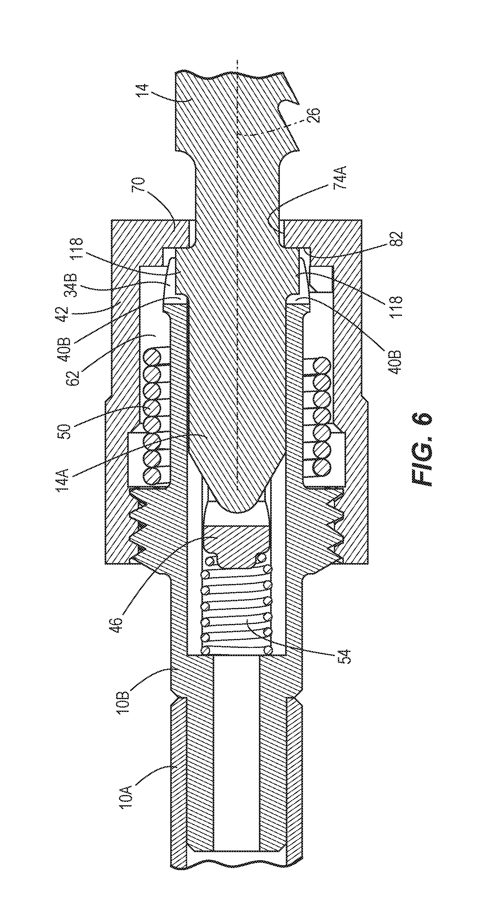
[0013] FIG. 6 is another cross-sectional view of the blade clamp of FIG. 5 in a locked configuration.
[0014] FIG. 7 is a plan view of the power tool in accordance with the embodiment of the invention of FIG. 1.
[0015] Before any embodiments of the invention are explained in detail, it is to be understood that the invention is not limited in its application to the details of construction and the arrangement of components set forth in the following description or illustrated in the following drawings. The invention is capable of other embodiments and of being practiced or of being carried out in various ways. Also, it is to be understood that the phraseology and terminology used herein is for the purpose of description and should not be regarded as limiting.
DETAILED DESCRIPTION
[0016] FIG. 1 illustrates a spindle 10 of a power tool 12 (FIG. 7), a cutting blade 14, and a blade clamp 22 for selectively securing the blade 14 to the spindle 10. In the illustrated embodiment, as shown in FIG. 7, the power tool 12 is a jigsaw and reciprocating motion is imparted to the spindle 10 and the connected blade 14 for cutting a workpiece. The power tool 12 includes a housing 15 for supporting a motor 16 and a gear train 17 (shown schematically). The spindle 10 is connected to an output of the gear train 17 for relative movement therewith.
[0017] With reference to FIGS. 1, 2, and 5, the spindle 10 defines a longitudinal axis 26 extending through the blade clamp 22 and the blade 14. In the illustrated embodiment, the spindle 10 includes a first portion 10A and a separate, second portion 10B partially received within and coupled for co-rotation with the first portion 10A (FIG. 5). The first portion 10A is connectable to a reciprocating mechanism in the jigsaw 12 (e.g., a scotch yoke mechanism). The second portion 10B of the spindle 10 is a body 10B, which is a component of the blade clamp 22, having a plurality of thread segments 18 (FIG. 2) on the outer periphery thereof. The body 10B includes a bore 30 coaxial with the longitudinal axis 26 and two pairs of aligned, laterally spaced notches 34A, 34B that extend radially inward from the outer periphery of the body 10B and communicate with the bore 30 (FIG. 2). The bore 30 and the notches 34A, 34B extend from an end 38 of the body 10B opposite the first portion 10A of the spindle 10 to respective bottom ends 40A, 40B of the notches 34A, 34B. Although the body 10B is a separate portion of the spindle 10 in the illustrated embodiment, the body 10B may alternatively be integrally formed with the spindle 10 as a single piece.
[0018] With reference to FIGS. 2-6, the blade clamp 22 also includes a cover 42, an ejection pin 46 positioned within the bore 30, and a torsion spring 50 coupling the body 10B and the cover 42 (FIG. 5). The blade clamp 22 further includes a compression spring 54 positioned within the bore 30 for biasing the ejection pin 46 toward the end 38 of the body 10B.
[0019] With continued reference to FIGS. 2-6, the cover 42 has a generally cylindrical shape and includes an inner surface 62 (FIG. 3), a first end 66A, and an opposite second end 66B. The cover 42 includes threads 64 on the inner surface 62 proximate the first end 66A engaged with the thread segments 18 on the body 10B (FIG. 5). The cover 42 includes a face 70 at the second end 66B (FIG. 3). The face 70 includes a slot 74 (FIG. 2) having a first, circular portion 74A, and second, lateral portions 74B extending from opposite sides of the circular portion 74A perpendicular to the longitudinal axis 26. The blade 14 is receivable through the slot 74.
[0020] With reference to FIG. 3, the cover 42 further includes multiple internal shoulders 78 proximate the second end 66B and adjacent the face 70. The shoulders 78 extend radially inward from the inner surface 62 and define slots 86 (only one of which is shown in FIG. 3) therebetween. In the illustrated embodiment of the blade clamp 22, the cover 42 includes two slots 86, spaced laterally on opposite sides of the longitudinal axis 26, positioned at an angle of about ninety degrees relative to the slot 74.
[0021] With reference to FIGS. 2, 5, and 6, the ejection pin 46 includes two projections 94, spaced laterally on opposite sides of the longitudinal axis 26, extending radially outward. The pin 46 has a generally cylindrical shape and includes a slot 98 (FIGS. 2 and 5) at one end 46A extending along the length of the pin 46. As described in more detail below, the slot 98 is aligned with the slot 74 in the cover 42 when the blade 14 is inserted into the blade clamp 22. With reference to FIG. 5, the cylindrical end 46A of the pin 46 may extend through (i.e., telescope from) the circular portion 74A of the slot 74 beyond the face 70 of the cover 42.
[0022] With reference to FIGS. 2 and 4, the projections 94 on the ejection pin 46 are slidably receivable within the respective slots 86 in the interior of the cover 42. Furthermore, the projections 94 are also slidably received in the respective notches 34A in the body 10B, thereby rotationally constraining the pin 46 relative to the body 10B.
[0023] With reference to FIG. 5, the compression spring 54 includes opposite ends 106A, 106B. The first end 106A is seated against an internal shoulder that at least partially defines the bore 30, and the second end 106B is seated against an end 46B of the pin 46 opposite the cylindrical end 46A. Therefore, the compression spring 54 biases the pin 46 along the longitudinal axis 26 toward the end 38 of the body 10B. As such, the pin 46 is displaceable within the body 10B in opposite directions along the longitudinal axis 26.
[0024] With reference to FIG. 2, the torsion spring 50 includes ends 114A, 114B coupled, respectively, to the body 10B and the cover 42. The torsion spring 50 biases the cover 42 toward a first rotational position relative to the body 10B coinciding with a locked configuration of the blade clamp 22. The cover 42 is rotatable against the bias of the torsion spring 50 toward a second rotational position relative to the body 10B coinciding with an unlocked configuration of the blade clamp 22. Specifically, the torsion spring 50 is configured to rotate the cover 42 about the thread segments 18 such that the cover 42 is also axially displaceable along the body 10B relative to the longitudinal axis 26 when the blade clamp 22 is adjusted between the first and second rotational positions.
[0025] With reference to FIG. 2, the blade 14 includes a stem portion 14A and two shoulder portions 118 extending laterally from the stem portion 14A. The stem portion 14A is receivable within the blade clamp 22, specifically through the aligned slots 74, 98 in the cover 42 and the pin 46, respectively. The slot 74 is sufficiently wide (i.e., in a radial direction) for the shoulder portions 118 of the blade 14 to pass completely through the slot 74 for positioning on the interior side of the face 70 (as shown in FIG. 6). The shoulder portions 118 are further receivable in the respective notches 34B (FIG. 2) of the body 10B.
[0026] With reference to FIG. 6, in the locked configuration of the blade clamp 22, the slot 74 is rotationally misaligned with the slot 98 in the ejection pin 46 (and the notches 34B in the body 10B), such that the shoulder portions 118 of the blade 14 are positioned adjacent and in contact with an interior surface 82 of the face 70. The blade 14 extends through the circular portion 74A of the slot 74, while the shoulder portions 118 engage the interior surface 82 of the face 70. Furthermore, the axial displacement of the cover 42, as it is moved from the second rotational position to the first rotational position, clamps the shoulder portions 118 between the interior surface 82 and the respective bottom ends 40B of the notches 34B. The compression spring 54 may further bias the shoulder portions 118 against the interior surface 82.
[0027] In operation, with reference to FIGS. 5 and 6, the blade clamp 22 is adjustable between an open, unlocked configuration (FIG. 5) and a closed, locked configuration (FIG. 6). When the blade clamp 22 is in the unlocked configuration, the projections 94 on the pin 46 are positioned within the respective slots 86 in the cover 42. Because the pin 46 is rotationally constrained to the body 10B as described above, the projections 94 inhibit rotational movement of the cover 42 when positioned in the slots 86. The compression spring 54 maintains the projections 94 against the interior surface 82 (FIG. 3) of the face 70 for maintaining the blade clamp 22 in the unlocked configuration, in which the slots 74, 98 are rotationally aligned about the longitudinal axis 26 for receiving the stem portion 14A of the blade 14.
[0028] During insertion of the stem portion 14A of the blade 14 through the aligned slots 74, 98, continued displacement of the blade 14 in the insertion direction also displaces the ejection pin 46 rearward (i.e., to the left from the frame of reference of FIGS. 5 and 6) along the longitudinal axis 26 against the bias of the spring 54. Subsequently, the projections 94 are removed from the slots 86 in the cover 42, permitting the torsion spring 50 to rebound and rotate the cover 42 from the second rotational position (where the slots 74, 98 are rotationally aligned) toward the first rotational position (where the slots 74, 98 are rotationally misaligned). The slots 34A in the body 10B are longer than the slots 86 in the cover 42, allowing the shoulder portions 118 of the blade 14 to be positioned rearward of the interior surface 82 of the face 70 (FIG. 6). The cover 42 moves axially rearward (i.e., to the left from the frame of reference of FIG. 6) along the body 10B when adjusting to the first rotational position such that the interior surface 82 moves toward the shoulder portions 118. Once the cover 42 has reached its first rotational position and the blade 14 has been released by the user, the shoulder portions 118 are clamped between the interior surface 82 of the face 70 and the bottom ends 40B of the notches 34B for locking the blade clamp 22 in the locked configuration. As such, insertion of the blade 14 by a user automatically adjusts the blade clamp 22 from the unlocked configuration to the locked configuration. Because the blade clamp 22 is normally maintained in the unlocked configuration when a blade 14 is not attached, the blade clamp 22 may allow insertion of the blade 14 by the user only using one hand.
[0029] To adjust the blade clamp 22 from the locked configuration to the unlocked configuration, the user rotates the cover 42 from the first rotational position against the bias of the torsional spring 50 toward the second rotational position, axially displacing the interior surface 82 of the face 70 away from the shoulder portions 118, thereby releasing the clamping force on the blade 14. Subsequently, the slots 74, 98 are re-aligned such that the shoulder portions 118 of the shank 14A no longer engage the interior surface 82. The compression spring 54 rebounds to displace the pin 46 forward along the longitudinal axis 26, ejecting the blade 14 from the blade clamp 22 through the slot 74. The projections 94 are again received within the slots 86 in the cover 42 upon the pin 46 reaching its forward-most position within the bore 30, again maintaining the blade clamp 22 in the unlocked configuration.
[0030] Various features of the invention are set forth in the following claims.
* * * * *
D00000
D00001
D00002
D00003
D00004
D00005
D00006
D00007
XML
uspto.report is an independent third-party trademark research tool that is not affiliated, endorsed, or sponsored by the United States Patent and Trademark Office (USPTO) or any other governmental organization. The information provided by uspto.report is based on publicly available data at the time of writing and is intended for informational purposes only.
While we strive to provide accurate and up-to-date information, we do not guarantee the accuracy, completeness, reliability, or suitability of the information displayed on this site. The use of this site is at your own risk. Any reliance you place on such information is therefore strictly at your own risk.
All official trademark data, including owner information, should be verified by visiting the official USPTO website at www.uspto.gov. This site is not intended to replace professional legal advice and should not be used as a substitute for consulting with a legal professional who is knowledgeable about trademark law.