Adapter For Laboratory Cell Strainer
Demsia; Walter ; et al.
U.S. patent application number 15/920939 was filed with the patent office on 2019-09-19 for adapter for laboratory cell strainer. The applicant listed for this patent is MTC Bio, Inc.. Invention is credited to Michael Demsia, Walter Demsia.
| Application Number | 20190283028 15/920939 |
| Document ID | / |
| Family ID | 67904969 |
| Filed Date | 2019-09-19 |


| United States Patent Application | 20190283028 |
| Kind Code | A1 |
| Demsia; Walter ; et al. | September 19, 2019 |
ADAPTER FOR LABORATORY CELL STRAINER
Abstract
An adapter for laboratory cell strainer is disclosed. The adapter includes a unitary structure having an annular top surface, an annular bottom surface, a smooth inner surface, an outer surface, and an opening extending therethrough. The adapter has a downwardly and radially inwardly sloped funnel section terminating in a cylindrical edge at the annular bottom surface with a lower section of the funnel section having a narrowed, tapered diameter. The outer surface of a middle section of the funnel section has an annular neck configured therearound with a plurality of radially protruding ribs. The unitary structure is configured for connection to the laboratory cell strainer at the annular top surface and placement inside a various sized laboratory tube for receiving filtered liquid during use.
| Inventors: | Demsia; Walter; (Holmdel, NJ) ; Demsia; Michael; (Jersey City, NJ) | ||||||||||
| Applicant: |
|
||||||||||
|---|---|---|---|---|---|---|---|---|---|---|---|
| Family ID: | 67904969 | ||||||||||
| Appl. No.: | 15/920939 | ||||||||||
| Filed: | March 14, 2018 |
| Current U.S. Class: | 1/1 |
| Current CPC Class: | B01D 2201/182 20130101; B01L 2200/023 20130101; B65B 29/02 20130101; B01D 29/01 20130101; B01D 61/18 20130101; B01L 2200/026 20130101; B01D 23/28 20130101; B01L 2300/12 20130101; B01D 2201/30 20130101; B01L 3/56 20130101; B01D 29/05 20130101; B01L 3/5635 20130101; G01N 1/28 20130101; B01D 2201/309 20130101; A62B 7/00 20130101; B01L 3/563 20130101; B01D 29/085 20130101; B01L 2300/0681 20130101; B01L 2200/12 20130101; B01L 2300/0832 20130101; B01D 35/00 20130101 |
| International Class: | B01L 3/00 20060101 B01L003/00 |
Claims
1. An adapter for laboratory cell strainer, comprising: a unitary structure having an annular top surface, an annular bottom surface, a smooth inner surface, an outer surface, and an opening extending therethrough, and having a downwardly and radially inwardly sloped funnel section terminating in a cylindrical edge at the annular bottom surface with a lower section of the funnel section having a narrowed, tapered diameter, and the outer surface of a middle section of the funnel section having an annular neck configured therearound with a plurality of radially protruding ribs; wherein the unitary structure is configured for connection to the laboratory cell strainer at the annular top surface and placement inside a various sized laboratory tube for receiving filtered liquid during use.
2. The adapter of claim 1, wherein the middle section of the funnel section is configured with a tapered diameter that is greater than the narrowed, tapered diameter of the lower section of the funnel section.
3. The adapter of claim 2, wherein an upper section of the funnel section is configured with a tapered diameter that is greater than the tapered diameter of the middle section of the funnel section.
4. The adapter of claim 3, wherein the upper section of the funnel section is configured with a gradual radially inward slope for directing the filtered liquid therethrough.
5. The adapter of claim 1, wherein the plurality of radially protruding ribs are longitudinal and oriented vertically for providing stability and a secure fit inside the various sized laboratory tube during use.
6. The adapter of claim 1, wherein the plurality of radially protruding ribs are configured to gradually flare outward from a proximal end to a distal end of the annular neck.
7. The adapter of claim 1, wherein the plurality of radially protruding ribs are evenly or unevenly spaced therearound the annular neck on the outer surface of the middle section of the funnel section.
8. The adapter of claim 1, wherein the plurality of radially protruding ribs are configured for preventing air lock, thereby allowing the filtered liquid to flow freely into the various sized laboratory tube during use.
9. The adapter of claim 1, wherein at least some of the middle section of the funnel section is dimensioned or shaped to provide a frictional engagement with the various sized laboratory tube during use.
10. The adapter of claim 1, wherein the smooth inner surface and the downwardly and radially inwardly sloped funnel section of the unitary structure are configured for directing the filtered liquid therethrough the opening at the annular bottom surface without any residual filtered liquid left behind.
11. The adapter of claim 1, wherein the smooth inner surface of the middle section is configured with a gradual radially inward slope for directing the filtered liquid therethrough.
12. The adapter of claim 1, wherein the adapter is manufactured via 3D printing, injection molding, extrusion molding or vacuum molding.
13. The adapter of claim 1, wherein the adapter is fabricated of polycarbonate plastic, polyethylene plastic or polypropylene plastic.
Description
TECHNICAL FIELD
[0001] The present disclosure relates to the field of laboratory products for scientific research, and more particularly, to an improved adapter for use with laboratory cell strainer systems in the handling of biological and chemical filtered liquid.
BACKGROUND
[0002] Conventional adapters used in the laboratory environment have many disadvantages. First, a single conventional adapter is unable to fit various sized laboratory tubes and hence if a variety of adapter sizes is required, a large inventory of adapters must be acquired and stored. Second, existing adapters fail to provide a secure fit and stability when used with various sized laboratory tubes. Third, conventional adapters tend to have sharp, interior surfaces that are prone to catching or retaining liquids. Fourth, existing adapters used with laboratory cell strainer systems have not solved the problem of air-lock, which prevents filtered liquid from flowing freely into the laboratory tube.
[0003] It would thus be desirable to have an improved adapter for use with other laboratory products, among other desirable features as described herein, which avoids the disadvantages of conventional adapters used in the laboratory.
SUMMARY
[0004] In a first aspect, there is provided herein an adapter for laboratory cell strainer, according to the present disclosure. The adapter includes a unitary structure having an annular top surface, an annular bottom surface, a smooth inner surface, an outer surface, and an opening extending therethrough. The adapter has a downwardly and radially inwardly sloped funnel section terminating in a cylindrical edge at the annular bottom surface with a lower section of the funnel section having a narrowed, tapered diameter. The outer surface of a middle section of the funnel section has an annular neck configured therearound with a plurality of radially protruding ribs. The unitary structure is configured for connection to the laboratory cell strainer at the annular top surface and placement inside a various sized laboratory tube for receiving filtered liquid during use.
[0005] In certain embodiments, the middle section of the funnel section is configured with a tapered diameter that is greater than the narrowed, tapered diameter of the lower section of the funnel section.
[0006] In certain embodiments, an upper section of the funnel section is configured with a tapered diameter that is greater than the tapered diameter of the middle section of the funnel section.
[0007] In certain embodiments, the upper section of the funnel section is configured with a gradual radially inward slope for directing the filtered liquid therethrough.
[0008] In certain embodiments, the plurality of radially protruding ribs are longitudinal and oriented vertically for providing stability and a secure fit inside the various sized laboratory tube during use.
[0009] In certain embodiments, the plurality of radially protruding ribs are configured to gradually flare outward from a proximal end to a distal end of the annular neck.
[0010] In certain embodiments, the plurality of radially protruding ribs are evenly or unevenly spaced therearound the annular neck on the outer surface of the middle section of the funnel section.
[0011] In certain embodiments, the plurality of radially protruding ribs are configured for preventing air lock, thereby allowing the filtered liquid to flow freely into the various sized laboratory tube during use.
[0012] In certain embodiments, at least some of the middle section of the funnel section is dimensioned or shaped to provide a frictional engagement with the various sized laboratory tube during use.
[0013] In certain embodiments, the smooth inner surface and the downwardly and radially inwardly sloped funnel section of the unitary structure are configured for directing the filtered liquid therethrough the opening at the annular bottom surface without any residual filtered liquid left behind.
[0014] In certain embodiments, the smooth inner surface of the middle section is configured with a gradual radially inward slope for directing the filtered liquid therethrough.
[0015] In certain embodiments, the adapter is manufactured via 3D printing, injection molding, extrusion molding or vacuum molding.
[0016] In certain embodiments, the adapter is fabricated of polycarbonate plastic, polyethylene plastic or polypropylene plastic.
[0017] Various advantages of this disclosure will become apparent to those skilled in the art from the following detailed description, when read in light of the accompanying drawings.
BRIEF DESCRIPTION OF THE DRAWINGS
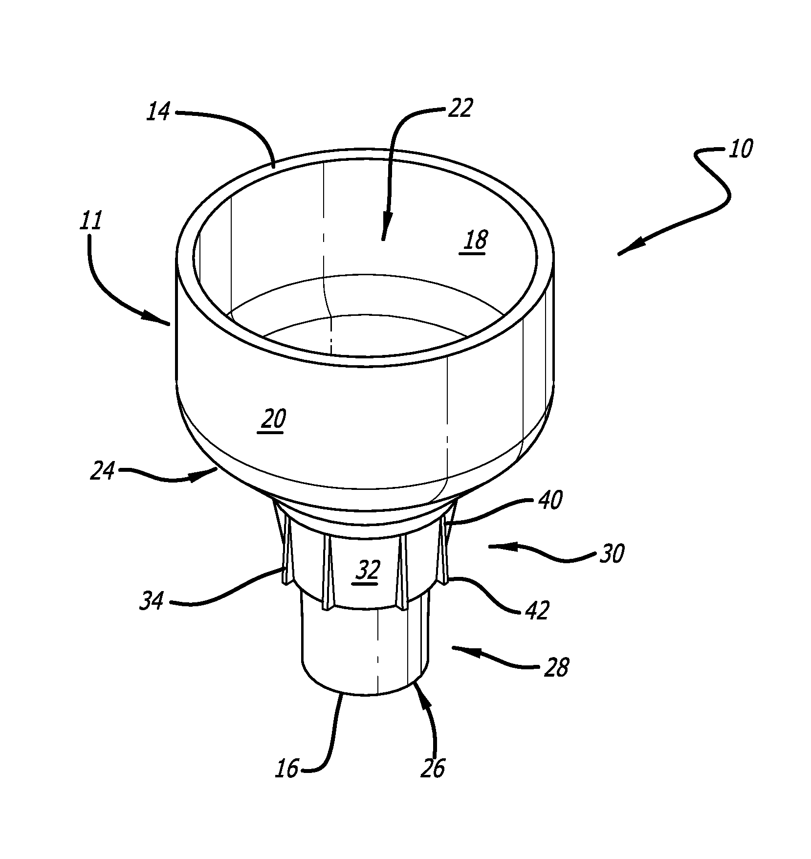
[0018] FIG. 1 is a top perspective view of an adapter in accordance with an example embodiment of the present disclosure.
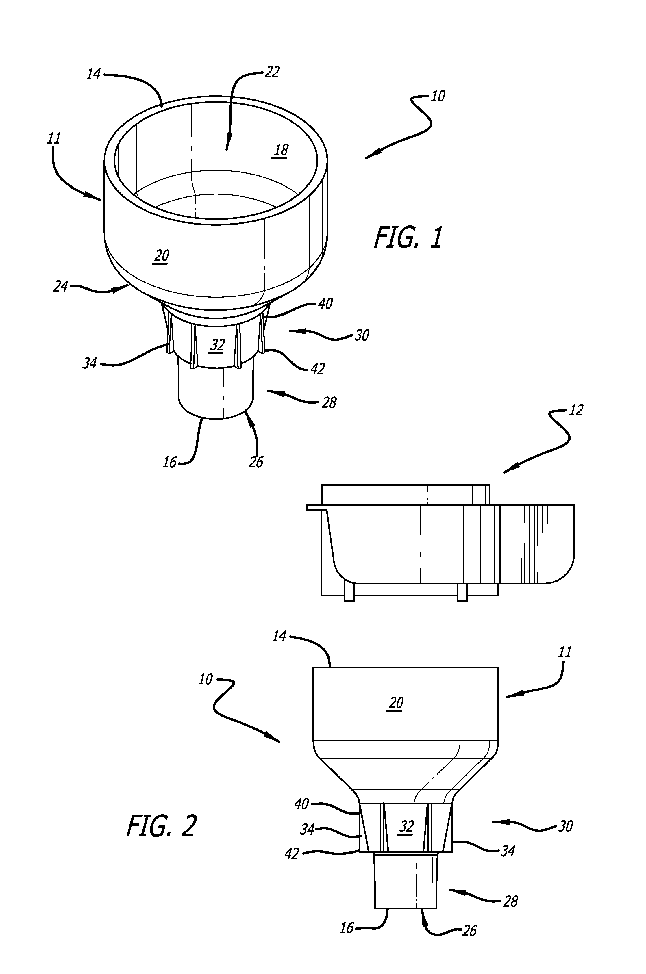
[0019] FIG. 2 is a side elevation view of a laboratory cell strainer and the adapter of FIG. 1 showing alignment of the laboratory cell strainer for securing atop and therein the adapter in accordance with an example embodiment of the present disclosure.
[0020] FIG. 3 is side elevation view of the laboratory cell strainer and the adapter of FIG. 2 showing use with various sized laboratory tubes in accordance with an example embodiment of the present disclosure.
[0021] FIG. 4 is a side elevation view of the laboratory cell strainer and the adapter of FIG. 3 secured therein a various sized laboratory tube in accordance with an example embodiment of the present disclosure.
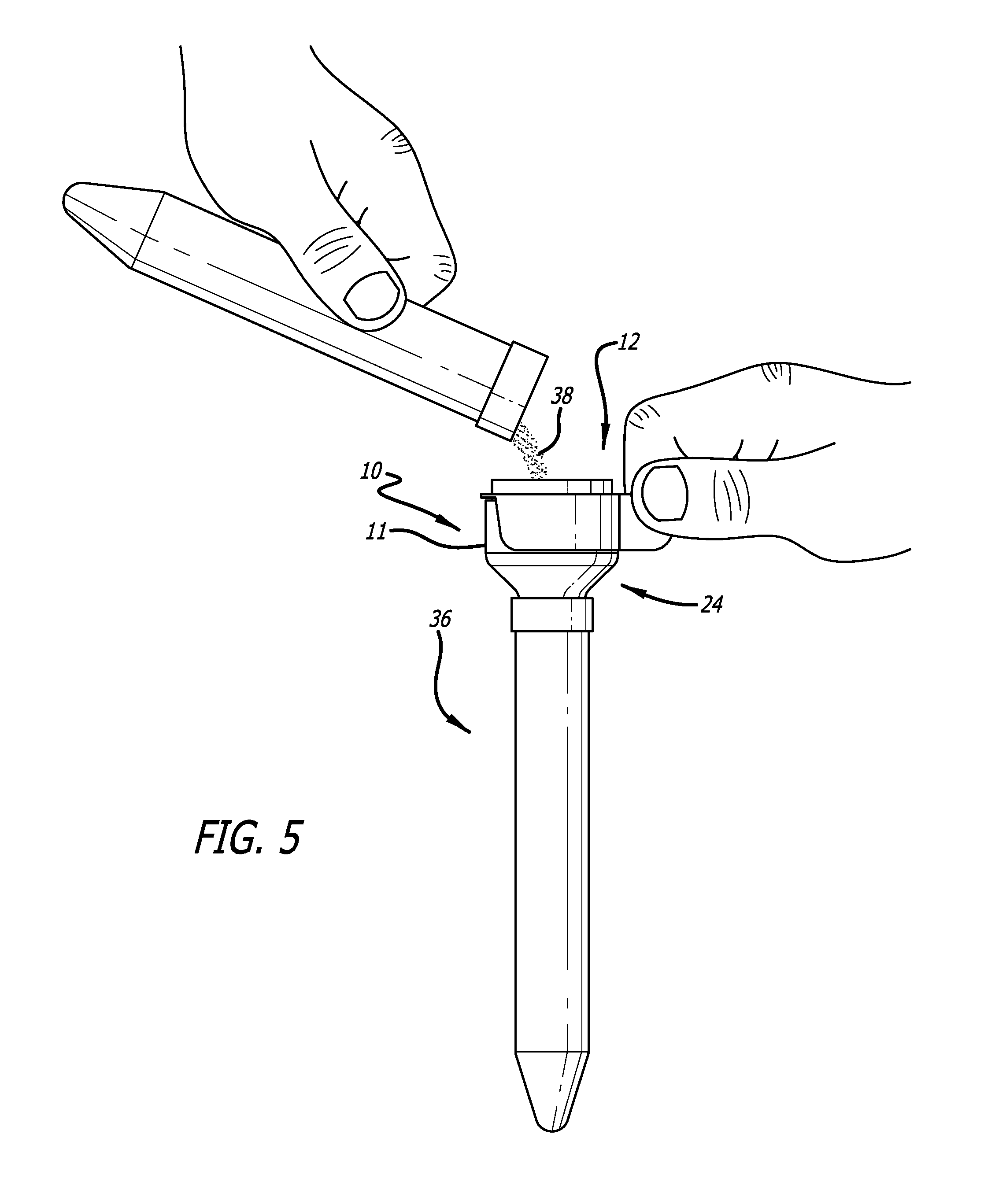
[0022] FIG. 5 is a side elevation view of a laboratory sample being poured into the laboratory cell strainer and the adapter of FIG. 4 in accordance with an example embodiment of the present disclosure.
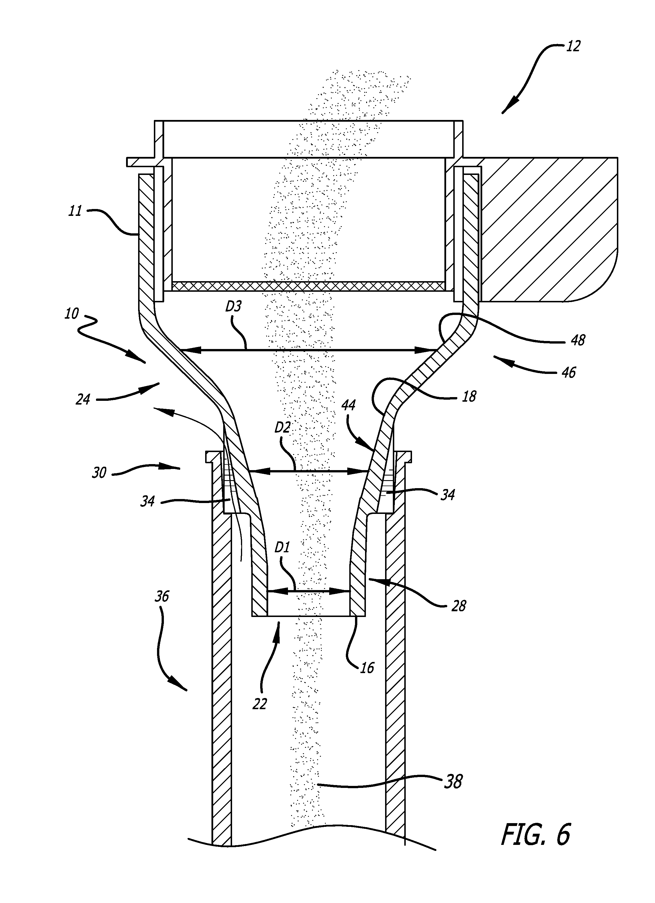
[0023] FIG. 6 is a cross-section view of the laboratory cell strainer and the adapter secured therein a various sized laboratory tube in use in accordance with an example embodiment of the present disclosure.
DETAILED DESCRIPTION
[0024] This disclosure is not limited to the particular apparatus, systems, methodologies or protocols described, as these may vary. The terminology used in this description is for the purpose of describing the particular versions or embodiments only, and is not intended to limit the scope.
[0025] As used in this document, the singular forms "a," "an," and "the" include plural reference unless the context clearly dictates otherwise. Unless defined otherwise, all technical and scientific terms used herein have the same meanings as commonly understood by one of ordinary skill in the art. All sizes recited in this document are by way of example only, and the disclosure is not limited to structures having the specific sizes or dimensions recited below. As used herein, the term "comprising" means "including, but not limited to."
[0026] In consideration of the figures, it is to be understood for purposes of clarity that certain details of construction and/or operation are not provided in view of such details being conventional and well within the skill of the art upon disclosure of the document described herein.
[0027] The present disclosure pertains to an adapter for use with laboratory strainer. The adapter enables various brands of cell strainer products to be used with various sizes and brands of laboratory tubes rather than being limited to large (50 mL) laboratory tubes. The adapter, with its tapered and vertically oriented ribbed design, provides stability and a secure fit inside various sized laboratory tubes during use. The smooth inner surface and downwardly and radially inwardly sloped funnel section of the adapter are designed for directing filtered liquid therethrough the opening at the annular bottom surface without any residual filtered liquid left behind. When used concurrently with the cell strainer, the adapter prevents air lock, thereby allowing liquid to flow freely into various sized laboratory tubes. Thus, the adapter makes decanting liquids into various sized laboratory tubes less prone to spillage.
[0028] Referring now to FIG. 1 is a top perspective view of the adapter 10 for laboratory cell strainer 12 according to the present disclosure. FIG. 2 is a side elevation view of the laboratory cell strainer 12 and the adapter 10 showing alignment of the laboratory cell strainer 12 for securing atop and therein the adapter 10. The adapter 10 includes a unitary structure 11 having an annular top surface 14, an annular bottom surface 16, a smooth inner surface 18, an outer surface 20, and an opening 22 extending therethrough. The adapter 10 has a downwardly and radially inwardly sloped funnel section 24 terminating in a cylindrical edge 26 at the annular bottom surface 16 with a lower section 28 of the funnel section 24 having a narrowed, tapered diameter D1. The outer surface 20 of a middle section 30 of the funnel section 24 has an annular neck 32 configured therearound with a plurality of radially protruding ribs 34. The unitary structure 11 is configured for connection to the laboratory cell strainer 12 at the annular top surface 14 and placement inside a various sized laboratory tube 36 (FIGS. 3-6) for receiving a laboratory sample or filtered liquid 38 (FIGS. 5-6) during use.
[0029] In the illustrated embodiments, the plurality of radially protruding ribs 34 are longitudinal and oriented vertically for providing stability and a secure fit inside the various sized laboratory tube 36 during use.
[0030] In some embodiments, the plurality of radially protruding ribs 34 are configured to gradually flare outward from a proximal end 40 to a distal end 42 of the annular neck 32.
[0031] In other embodiments, the plurality of radially protruding ribs 34 can be either evenly spaced or unevenly spaced in any suitable configuration therearound the annular neck 32 on the outer surface 20 of the middle section 30 of the funnel section 24.
[0032] In further embodiments, the plurality of radially protruding ribs 34 are configured for preventing air lock when used with the laboratory cell strainer (see airflow direction represented by arrows in FIG. 6), thereby allowing the filtered liquid 38 to flow freely into the various sized laboratory tube 36 (a 5 ml tube in this embodiment) during use.
[0033] In other embodiments, at least some of the middle section 30 of the funnel section 24 is dimensioned or shaped to provide a frictional engagement with the various sized laboratory tube during use.
[0034] FIG. 3 is side elevation view of the laboratory cell strainer 12 and the adapter 10 showing use with various sized laboratory tubes 36. FIG. 4 is a side elevation view of the laboratory cell strainer 12 and the adapter 10 secured therein a various sized laboratory tube 36. It is to be understood that the adapter 10 of the present disclosure is configured for use with various sized laboratory tubes 36 in standard sizes, including, but not limited to, 5 ml, 15 ml, 10 mm, 12 mm, and the like.
[0035] FIG. 5 is a side elevation view of a laboratory sample 38 being poured into the laboratory cell strainer 12 and the adapter 10. FIG. 6 is a cross-section view of the laboratory cell strainer 12 and the adapter 10 secured therein a various sized laboratory tube 36 in use with filtered liquid 38 flowing therethrough. In the illustrated embodiments, the smooth inner surface 18 and the downwardly and radially inwardly sloped funnel section 24 of the unitary structure 11 are configured for directing the filtered liquid 38 therethrough the opening 22 at the annular bottom surface 16 without any residual filtered liquid 38 left behind. The smooth inner surface 18 of the middle section 30 of the funnel section 24 is configured with a gradual radially inward slope 44 for directing the filtered liquid 38 therethrough.
[0036] In some embodiments, the middle section 30 of the funnel section 24 is configured with a tapered diameter D2 that is greater than the narrowed, tapered diameter D1 of the lower section 28 of the funnel section 24.
[0037] In other embodiments, an upper section 46 of the funnel section 24 is configured with a tapered diameter D3 that is greater than the tapered diameter D2 of the middle section 30 of the funnel section 24.
[0038] In further embodiments, the upper section 46 of the funnel section 24 is configured with a gradual radially inward slope 48 for directing the filtered liquid 38 therethrough.
[0039] In accordance with the present disclosure, the adapter 10 can be manufactured via 3D printing, injection molding, extrusion molding, vacuum molding or any suitable manufacturing process.
[0040] It is to be understood that the adapter 10 can be fabricated of polycarbonate plastic, polyethylene plastic, polypropylene plastic, or any suitable sturdy material.
[0041] These and other advantages of the present disclosure will be apparent to those skilled in the art. Accordingly, it will be recognized by those skilled in the art that changes or modifications may be made to the above-described embodiments without departing from the broad inventive concepts of the present disclosure. It should therefore be understood that the present disclosure is not limited to the particular embodiments described herein, but is intended to include all changes and modifications that are within the scope and spirit of the disclosure as encompassed by the disclosure and figures herein and the following claims.
* * * * *
D00000
D00001
D00002
D00003
D00004
D00005
XML
uspto.report is an independent third-party trademark research tool that is not affiliated, endorsed, or sponsored by the United States Patent and Trademark Office (USPTO) or any other governmental organization. The information provided by uspto.report is based on publicly available data at the time of writing and is intended for informational purposes only.
While we strive to provide accurate and up-to-date information, we do not guarantee the accuracy, completeness, reliability, or suitability of the information displayed on this site. The use of this site is at your own risk. Any reliance you place on such information is therefore strictly at your own risk.
All official trademark data, including owner information, should be verified by visiting the official USPTO website at www.uspto.gov. This site is not intended to replace professional legal advice and should not be used as a substitute for consulting with a legal professional who is knowledgeable about trademark law.