Method and Apparatus for Altering Biomechanics of the Shoulder
Shenoy; Vivek
U.S. patent application number 16/431385 was filed with the patent office on 2019-09-19 for method and apparatus for altering biomechanics of the shoulder. The applicant listed for this patent is The Foundry LLC. Invention is credited to Vivek Shenoy.
| Application Number | 20190282273 16/431385 |
| Document ID | / |
| Family ID | 67904704 |
| Filed Date | 2019-09-19 |


View All Diagrams
| United States Patent Application | 20190282273 |
| Kind Code | A1 |
| Shenoy; Vivek | September 19, 2019 |
Method and Apparatus for Altering Biomechanics of the Shoulder
Abstract
Selectively placed implants are specifically configured and dimensioned to address pathologies of the shoulder joint arising from improper force distribution. By using appropriately sized and positioned implants as described herein, displacement of targeted connective and muscle tissues acting on the shoulder is accomplished in order to realign force vectors and/or alter moment arms loading the joint to achieve therapeutic effects without cutting bone and with minimal cutting of the connective tissues.
| Inventors: | Shenoy; Vivek; (Redwood City, CA) | ||||||||||
| Applicant: |
|
||||||||||
|---|---|---|---|---|---|---|---|---|---|---|---|
| Family ID: | 67904704 | ||||||||||
| Appl. No.: | 16/431385 | ||||||||||
| Filed: | June 4, 2019 |
Related U.S. Patent Documents
| Application Number | Filing Date | Patent Number | ||
|---|---|---|---|---|
| 15295677 | Oct 17, 2016 | 10349980 | ||
| 16431385 | ||||
| 62242099 | Oct 15, 2015 | |||
| Current U.S. Class: | 1/1 |
| Current CPC Class: | A61F 2002/30688 20130101; A61B 17/56 20130101 |
| International Class: | A61B 17/56 20060101 A61B017/56 |
Claims
1. A prosthesis for treating disorders of the shoulder, the prosthesis comprising: a fixation portion having an elongate shape with an inner bone engaging surface configured to be mounted to the humerus at a fixation site oriented along a longitudinal axis of the humerus; a displacement portion having an overall curvature around an axis generally parallel to the longitudinal axis of the humerus and spaced from the fixation portion along the longitudinal axis of the humerus when the fixation portion is mounted at the fixation site, the displacement portion including a bearing surface configured to engage and permit sliding of soft tissues thereacross, the bearing surface being smooth, rounded and free of holes, discontinuities or fixation attachments; and a spanning section joining the fixation portion and displacement portion, the spanning section angled away from the humerus with respect to the fixation portion when mounted at the fixation site to elevate the displacement portion away from the humerus; wherein the displacement portion and the spanning section are specifically configured and dimensioned together to position the displacement portion at least in part between a target tissue and the humerus with the bearing surface engaging the target tissue to displace the target tissue sufficiently to alter the location, angle, or magnitude of forces exerted thereby so as to achieve a therapeutic effect in the shoulder, said target tissue comprising a connective tissue or muscle of the shoulder.
2. The prosthesis of claim 1, wherein the target tissue is the deltoid muscle.
3. The prosthesis of claim 1, wherein the inner bone engaging surface of the fixation portion has a concave curvature about said longitudinal axis to approximately match the lateral surface of the humeral shaft at the fixation site.
4. The prosthesis of claim 1, wherein the spanning section extends laterally and cranially from the fixation portion to the displacement portion when mounted at the fixation site.
5. The prosthesis of claim 1, wherein the displacement portion is connected to the spanning section along a first edge with an opposing, free end having a convexly curved edge.
6. The prosthesis of claim 5, wherein the displacement portion has a spoon-like rounded shape substantially matching the lateral profile of the humeral head adjacent the gleno-humeral joint.
7. The prosthesis of claim 1, wherein the displacement portion is cantilevered by the spanning section in a plane laterally displaced from, or angled relative to, the fixation portion when mounted at the fixation site on a lateral side of the humeral shaft such that the displacement portion is spaced apart from a lateral bone surface to provide a space between the humeral head and the displacement portion in or through which non-target soft tissues may reside or move substantially without interference.
8. The prosthesis of claim 7, wherein the spanning section extends laterally and cranially at an oblique angle relative to fixation portion when mounted at a lateral fixation site such that a plane tangent to a surface of the spanning section is disposed at an angle between about 30.degree. to 60.degree. relative to a longitudinal centerline through fixation portion.
9. The prosthesis of claim 1, wherein the displacement portion is configured to avoid interference with the acromion during arm abduction.
10. The prosthesis of claim 9, wherein the displacement portion has a cranial end shaped and dimensioned such that the displacement portion is spaced caudally and/or laterally from the acromion when the arm is abducted.
11. The prosthesis of claim 10, wherein the cranial end of displacement portion is concave or flattened.
12. The prosthesis of claim 9, wherein the cranial end of the displacement portion is configured to slip under the acromion during arm abduction.
13. The prosthesis of claim 12, wherein the bearing surface of the displacement portion has a curvature about a first axis transverse to the humeral shaft with a first radius, and the cranial end curves toward the humerus about a second axis parallel to the first axis with a second radius, the second radius being less than the first radius.
14. The prosthesis of claim 12, wherein the cranial end has a tapered thickness.
Description
RELATED APPLICATION DATA
[0001] This application is a divisional application of U.S. Nonprovisional patent application Ser. No. 15/295,677, filed on Oct. 17, 2016, and titled Method and Apparatus for Altering Biomechanics of the Shoulder, which application claims the benefit of priority of U.S. Provisional Patent Application Ser. No. 62/242,099, filed Oct. 15, 2015, and titled Method and Apparatus for Altering Biomechanics of Articular Joints.
[0002] Related U.S. Nonprovisional patent application Ser. No. 15/295,677 was also a Continuation-in-Part of U.S. Nonprovisional patent application Ser. No. 13/002,829, filed on Jan. 6, 2011 (now U.S. Pat. No. 9,795,410), and titled Method and Apparatus for Force Redistribution in Articular Joints, which is a 371 of International Application No. PCT/US10/46996, filed Aug. 27, 2010, and which claims the benefit of priority of U.S. Provisional Application No. 61/237,518, filed Aug. 27, 2009, and of U.S. Provisional Application No. 61/288,692, filed Dec. 21, 2009. U.S. Nonprovisional patent application Ser. No. 15/295,677 was also a Continuation-in-Part of U.S. Nonprovisional patent application Ser. No. 15/017,098, filed on Feb. 5, 2016 (now U.S. Pat. No. 9,931,136), and titled Method and Apparatus For Altering Biomechanics of Articular Joints, which is a Continuation application of U.S. Nonprovisional patent application Ser. No. 13/843,128, filed on Mar. 15, 2013 (now U.S. Pat. No. 9,278,004); which application was a Nonprovisional of and claims priority to U.S. Provisional Patent Application Ser. No. 61/620,756 filed on Apr. 5, 2012 and U.S. Provisional Patent Application Ser. No. 61/695,406, filed on Aug. 31, 2012; U.S. Nonprovisional patent application Ser. No. 13/843,128 was also a Continuation-in-Part of U.S. Nonprovisional patent application Ser. No. 12/870,462, filed on Aug. 27, 2010 (now U.S. Pat. No. 8,597,362), which claims priority to U.S. Provisional Patent Application Ser. No. 61/237,518, filed Aug. 27, 2009, and U.S. Provisional Patent Application Ser. No. 61/288,692, filed Dec. 21, 2009. Each of these applications is incorporated herein by reference in its entirety.
FIELD OF THE INVENTION
[0003] The present invention generally relates to the field of orthopedics. In particular, the present invention is directed to an interventional technique and implants for altering biomechanics of articular joints to provide a therapeutic effect. More particularly, embodiments of the present invention are directed to alleviating joint pain, effects of osteoarthritis ("OA") and increasing stability in the shoulder.
BACKGROUND
[0004] The human body contains many joints that permit articulation of varying degrees between bones. Those that permit free articulation are referred to as diarthroses. Examples include the hip, knee, elbow and shoulder. A variety of connective tissues are associated with the diarthroses joints, including intra-articular cartilages that provide cushioning and smooth sliding surfaces, ligaments that provide flexible connections between bones, and tendons that slide over joints and connect the muscles to provide motion. When connective tissues are compromised, joint pain and loss of function can result.
[0005] Osteoarthritis, or OA, is one of the most common causes of disability in the United States. OA is sometimes referred to as degenerative, or wear and tear, arthritis. OA is characterized by the breakdown of the articular cartilage within the joint. Over time, the cartilage may wear away entirely, resulting in bone-on-bone contact. Since bones, unlike cartilage, have many nerve cells, direct bone contact can be very painful to the OA sufferer. In addition to the pain and swelling, the OA sufferer can experience a progressive loss of mobility at the joint. This is due to loss of the joint space, where the articular cartilage has completely worn away.
[0006] Currently, various medications are often recommended to reduce the swelling and pain of OA. Other treatments such as weight loss, braces, orthotics, steroid injections and physical therapy may also help alleviate pain and restore function by strengthening muscles supporting the joint. However, since articular cartilage is avascular, or lacks a blood supply, repair and growth of adult cartilage is minimal. If the pain or immobility becomes too severe and other therapies do not alleviate the symptoms, surgical interventions become necessary. Surgical treatments include arthroscopy to clean the joint by removing loose fragments, osteotomy, or joint replacement.
Shoulder Anatomy
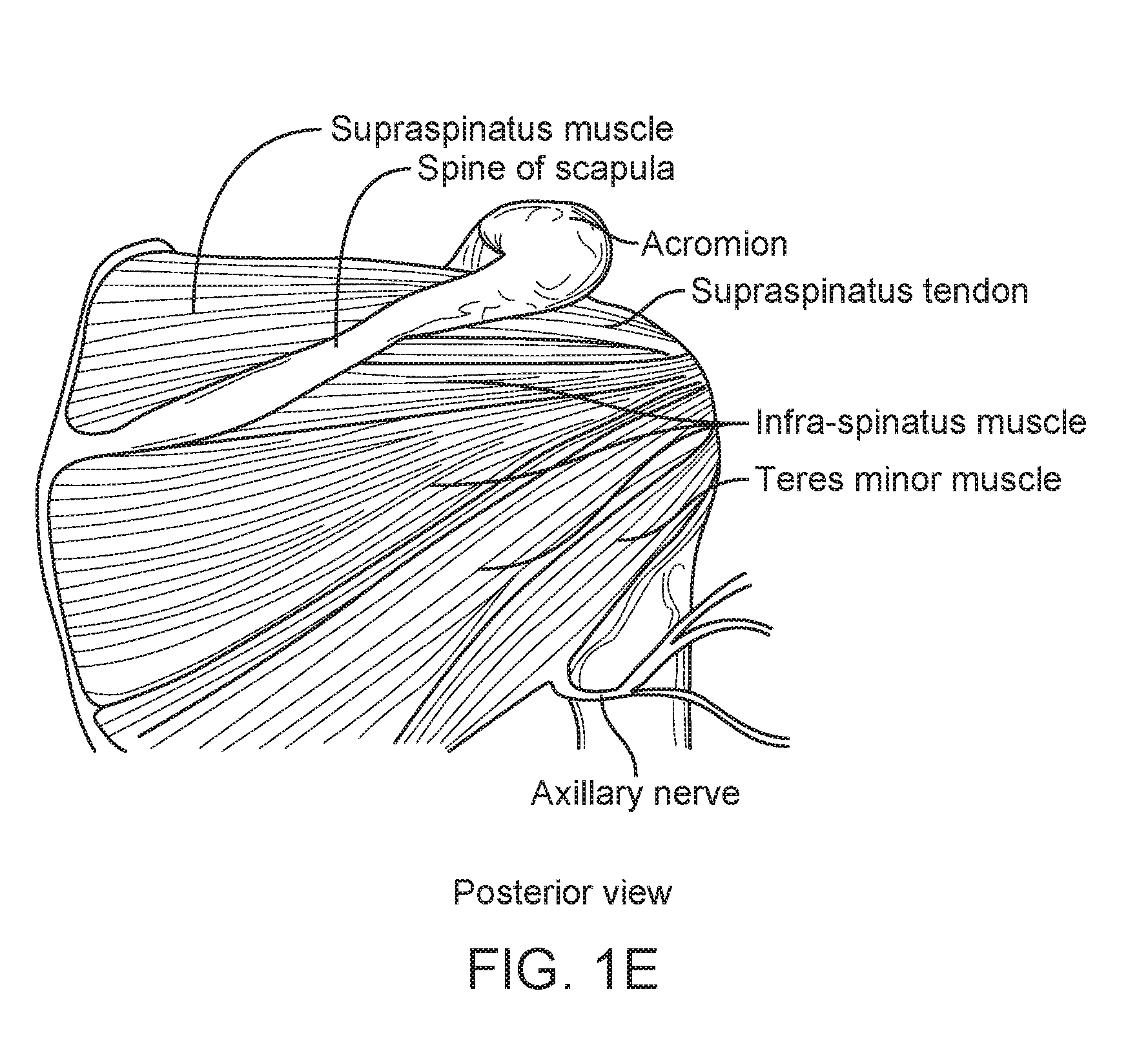
[0007] There are two joints in the shoulder. The gleno-humeral joint (also called the shoulder joint) is a ball-and-socket joint formed by the scapula and the head of the humerus bone (FIGS. 1A-E). This joint allows the shoulder to move forward and backward and the arm to move in a circular motion. The "socket" (the glenoid fossa of the scapula) is shallow, covering only a third of the "ball" (the head of the humerus). The socket is deepened by the glenoid labrum (see, e.g., FIG. 1C). The labrum is a fibro-cartilaginous rubbery structure that encircles the glenoid cavity effectively deepening the socket to increase static stability of the gleno-humeral joint. The acromioclavicular joint is formed by a part of the scapula called the acromion and the clavicle (see, e.g., FIG. 1A).
[0008] The acromioclavicular joint capsule is a soft tissue envelope that encircles the gleno-humeral joint and attaches to the scapula, humerus, and head of the biceps. It is lined by a thin, smooth synovial membrane.
[0009] The rotator cuff is a group of four tendons that connects muscles from the scapula and allows the shoulder to rotate and elevate. The four rotator cuff muscles--the subscapularis, supraspinatus, infraspinatus and teres minor muscles--provide support for the gleno-humeral joint.
[0010] The deltoid muscle (see, e.g., FIGS. 1B-C) is the largest, strongest muscle of the shoulder. It originates in three portions, the anterior, middle and posterior portions. The anterior portion flexes and medially rotates the arm, the middle portion abducts the arm and the posterior portion extends and laterally rotates the arm. The deltoid muscle takes over lifting the arm once the arm is away from the side of the body.
[0011] Rotator cuff tears, the most common injury of the shoulder, cause morphologic changes to cuff tendons and muscles, which can alter muscle architecture and moment arm. These alterations can affect shoulder performance in terms of muscle force and joint strength. Rotator cuff tears are often accompanied by tears in the glenoid labrum due to the alterations in the biomechanics of the shoulder joint.
SUMMARY OF THE DISCLOSURE
[0012] Selectively-placed implants are used to address pathologies of joints arising from improper force distribution. By using appropriately sized and positioned implants as described herein, displacement of targeted connective and muscle tissues surrounding the joint is accomplished in order to realign force vectors and/or alter moment arms loading the joint to achieve therapeutic effects without cutting bone and with minimal cutting of the connective tissues.
[0013] Exemplary methods disclosed herein comprise selecting at least one of the muscles and connective tissues associated with the shoulder joint as target tissue for treatment, and displacing the target tissue without severing the bones or target tissue, thereby redistributing loading in the joint to achieve a therapeutic effect.
[0014] In some embodiments of the invention, increased forces can be selectively applied to one side of a joint by forcing select muscle and/or connective tissues (target tissues) around a longer or more angled path, thus increasing the magnitude, altering the effective direction, and/or changing the moment arm of forces exerted by such muscles or tissues on the joint. This may be accomplished, for example, by appropriately-shaped implants that may be placed under selected target tissues relatively non-invasively compared to current surgical techniques for addressing such conditions. For example, in one embodiment, the implant may be secured to the humerus to increase stability in the shoulder.
[0015] In exemplary embodiments, the target tissue is displaced by placing an implant in contact with the target tissue. The implant may be secured to a bone and/or to soft tissues, which may include the target tissue. In a preferred embodiment, the implant reduces a load in a joint that includes the same bone to which the implant is secured. For example, the implant may be secured to the humerus in order to reduce or redistribute a load on an articular surface of the shoulder.
[0016] In another embodiment, the load is reduced on a region of the labrum on the glenoid. In one exemplary embodiment, the implant is completely outside the capsule surrounding the joint.
[0017] In some embodiments, the implant is secured on a first side of a joint to displace tissue on the first side of the joint in order to reduce a load on an opposing side of the joint. For example, the implant may be secured on a lateral side of the shoulder in order to beneficially alter loads or increase stability in the shoulder on the medial side.
[0018] In still further embodiments, connective tissue near a joint is displaced such that a moment arm through which the connective tissue acts upon the joint is increased. An implant may be secured to a bone near the joint such that the implant displaces the connective tissue sufficiently to increase the moment arm.
[0019] In preferred embodiments, connective tissue near a joint is displaced sufficiently to achieve a therapeutically effective reduction in a load in the joint. Usually loads will be reduced at least about 5%, preferably at least about 10%, more preferably at least about 15%. The magnitude of displacement required to achieve these load reductions will vary depending upon the joint, size and condition of the patient, and other factors.
[0020] In one embodiment for treatment of the shoulder joint, the target tissue may comprise the deltoid muscle. Such an embodiment of an implant is anchored onto the proximal shaft of the lateral humerus, and the deltoid muscle around the humeral head is displaced laterally, antero-laterally, or posterolaterally. The implant may include a fixation portion that is anchored by means of screws or other fixation devices to the humerus. A displacement portion coupled to the fixation portion may be positioned between the bone and the deltoid muscle so as to atraumatically engage and displace the deltoid muscle from its natural path to a therapeutic path, whereby loads in the shoulder joint are redistributed. The deltoid muscle may be displaced laterally, anterio-laterally or in other suitable directions relative to the humerus to achieve a therapeutic effect. In another shoulder treatment embodiment, the target tissue may comprise the biceps brachii tendon, in which case a fixation portion of an implant is anchored onto the proximal shaft of the humerus, and a displacement portion of the implant positioned to displace the biceps brachii tendon in a therapeutic direction, e.g. anteriorly.
[0021] In some embodiments the displacement portion is configured to avoid interference with the acromion during arm abduction. The displacement portion may have a cranial end shaped and dimensioned such that the displacement portion is spaced caudally and/or laterally from the acromion when the arm is abducted. For example, cranial end of displacement portion may be concave or flattened. Alternatively or additionally, the cranial end of the displacement portion may be configured to slip under the acromion during arm abduction. In addition, the displacement portion may be curved downward toward the humeral bone to avoid interference with the acromion during abduction of the arm. In such embodiments, the bearing surface may have a curvature about a first axis transverse to the humeral shaft with a first radius, and the cranial end may curve toward the humerus about a second axis parallel to the first axis with a second radius, the second radius being less than the first radius. In other embodiments, the cranial end of the displacement portion may have a tapered thickness so as to pass under the acromion during arm abduction.
[0022] By using the implants of the invention, appropriately-sized and positioned as described herein, displacement of targeted connective and muscle tissues surrounding the joint is accomplished in order to realign force vectors and/or alter moment arms loading the joint to achieve therapeutic effects without cutting bone and with minimal cutting of the connective tissues. Alternative and more specific devices and methodologies are described in more detail hereinbelow.
BRIEF DESCRIPTION OF DRAWINGS
[0023] For the purpose of illustrating the invention, the drawings show aspects of one or more exemplary embodiments of the invention. However, it should be understood that the present invention is not limited to the precise arrangements and instrumentalities shown in the drawings, wherein:
[0024] FIG. 1A is a front or anterior view of the shoulder joint with many muscles removed in order to reveal underlying bone, connective tissue and muscle structures;
[0025] FIG. 1B is a front or anterior view of the shoulder joint;
[0026] FIG. 1C is a coronal section view of the shoulder joint;
[0027] FIG. 1D is an anterior view of the shoulder joint;
[0028] FIG. 1E is a posterior view of the shoulder joint;
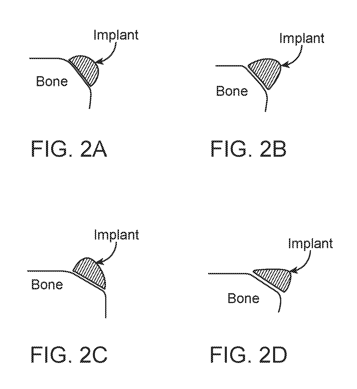
[0029] FIGS. 2A, 2B, 2C and 2D are schematic cross-sectional views of a displacement portion of a prostheses according to one embodiment of the present invention;
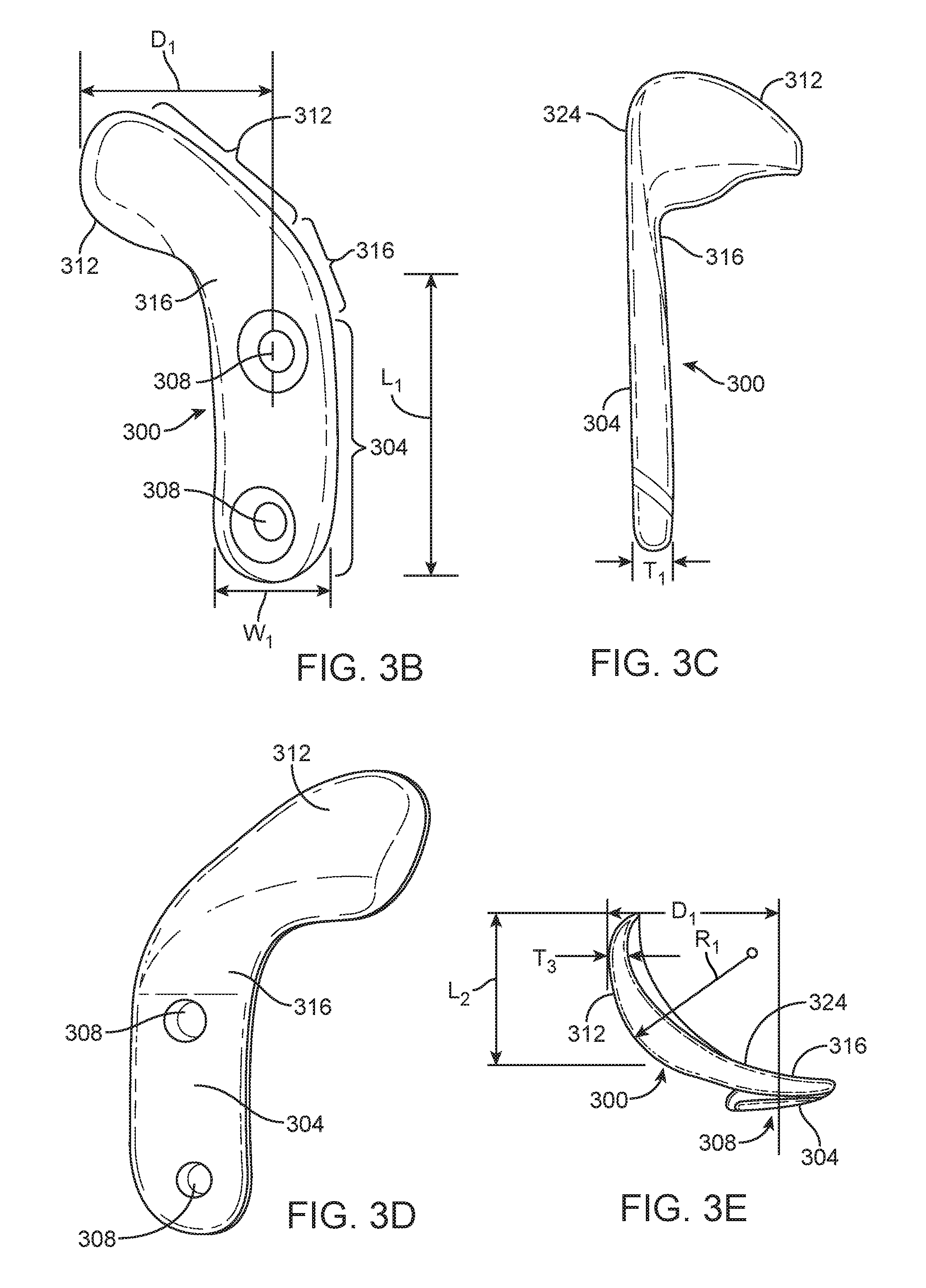
[0030] FIGS. 3A-H are views of an exemplary prosthesis for anterior displacement of the biceps brachii tendon in the shoulder, wherein FIG. 3A is a perspective view, FIG. 3B is an anterior (front) view, FIG. 3C is a lateral (side) view, FIG. 3D is a posterior (back) view, FIG. 3E is a caudal (top) view, and FIGS. 3F-H are further anterior views with the prosthesis implanted on the humerus;
[0031] FIGS. 3I and 3J are perspective views of further alternative embodiments employing supplemental fixation/support means;
[0032] FIG. 4 is a schematic view of the cranial end of the humerus adjacent a shoulder joint with a prosthesis implanted according to an exemplary embodiment of the present invention;
[0033] FIG. 5 is a schematic view of the cranial end of the humerus adjacent the shoulder joint with a prosthesis implanted according to an alternative exemplary embodiment of the present invention;
[0034] FIG. 6 is an anterior view of a right humerus illustrating positioning of an implant for treatment of shoulder indications requiring lateral and anterior displacements;
[0035] FIGS. 7A-I are views of an exemplary prosthesis for lateral displacement of the deltoid muscle in the shoulder in accordance with embodiments of the present invention, wherein FIG. 7A is a perspective view, FIG. 7B is a top view, FIG. 7C is a side view as seen from the anterior side of the implant, FIG. 7D is a side view as seen from the posterior side of the implant, FIG. 7E is a cross-sectional view of the implant sectioned through line A-A of FIG. 7B, FIG. 7F is a cross-sectional view of an alternative embodiment with two portions having different thicknesses, FIG. 7G is a lateral view implanted on the humerus, FIG. 7H is an anterior view implanted on the humerus, and FIG. 7I is a coronal section through the humerus;
[0036] FIG. 8 is a view illustrating positioning of an alternative exemplary embodiment of the present invention at the cranial end of the humerus to treat the shoulder;
[0037] FIG. 9 is a view illustrating positioning of an alternative exemplary embodiment of the present invention at the cranial end of the humerus to treat the shoulder;
[0038] FIG. 10 is a view illustrating positioning of an alternative exemplary embodiment of the present invention at the cranial end of the humerus to treat the shoulder;
[0039] FIGS. 11-25 are partial cross-sectional views of the end the humerus adjacent the shoulder illustrating alternative exemplary embodiments of the present invention;
[0040] FIGS. 26A-B are exemplary embodiments of the bearing unit of a two-part device; and
[0041] FIG. 27 is an exemplary embodiment of a composite bearing unit of a two-part device.
DETAILED DESCRIPTION
[0042] Joint conditions that result from or exacerbate unbalanced force distribution through the joint may be addressed in embodiments of the present invention by interventional techniques involving a redistribution of forces exerted on the joint without the need for highly invasive surgeries requiring significant trauma to the joint and associated muscle and connective tissues. In some embodiments of the invention, increased forces can be selectively applied to one side of a joint by forcing select muscle and/or connective tissues (target tissues) around a longer, more angled or curved path, or other path different from their pre-treatment, natural path, thus increasing the magnitude, altering the effective direction, and/or changing the moment arm of forces exerted by such muscles or tissues on the joint. This may be accomplished, for example, through the use of appropriately-shaped implants that may be placed under or adjacent selected target tissues relatively non-invasively compared to current surgical techniques for addressing such conditions.
[0043] Utilizing embodiments of the present invention, joint conditions that result from or exacerbate unbalanced force distribution through the joint may be addressed by interventional techniques involving a redistribution of forces exerted on the joint without the need for highly invasive surgeries requiring significant trauma to the joint and associated muscle and connective tissues. Redistribution of forces within the target joint in accordance with embodiments described herein may thus provide pain relief, slow down articular cartilage degeneration, and/or enhance cartilage regeneration.
[0044] The amount of displacement of the target tissue may not need to be large in order to provide a substantial therapeutic effect on the target joint. For example, in the knee, depending upon the nature of the disease and the size and geometry of a particular patient's joint, displacements of greater than about 5 mm up to about 30 mm may be sufficient, with displacements in the range of about 10 mm to about 30 mm also suitable, or more specifically about 10-20 mm. Of course, the specific magnitude and direction of displacement will depend upon the location and type of disease, the target tissue to be displaced, and other factors.
[0045] Exemplary embodiments of the invention described herein are particularly directed to treatment of the shoulder, although the principles of the invention may be applied to other joints as described in related co-pending applications and issued patents filed by and/or assigned to the present Applicant. In general, it will be appreciated by persons of ordinary skill in the art that specific features described in connection with one exemplary embodiment may be incorporated in other exemplary embodiments unless otherwise noted. The exemplary embodiments described are thus included to illustrate features of the invention, not limit it. It will be noted by persons of ordinary skill in the art that in some aspects general geometries and methodologies described herein are similar in certain respects to Applicant's prior disclosures with respect to treatment of other joints. However, persons of ordinary skill will also appreciate based on the teachings provided herein and in prior related disclosures that specific differences in configuration, dimension and technique as described herein are necessary for treatment of the shoulder, which is a primary focus of the present disclosure. For example, unlike the knee, the shoulder is a three-dimensional joint so the arm rotates anterior/posterior as well as up/down. To accommodate this greater and more complex range of motion, the area of the bearing surface configured to engage target tissue in the shoulder will typically be larger than in an embodiment configured to treat the knee as described in prior disclosures so target tissue does not slip off the bearing surface when the arm has anterior or posterior orientation. Also, in many shoulder embodiments, advantages may be realized by providing a relatively larger bearing surface area to help reduce tissue irritation and/or more broadly distribute load due to the absence of other interfering structures, such as the patella, which may limit implant size and shape. As another example, the displacement portion and bearing surface in embodiments described herein for treatment of the shoulder will typically be more symmetrical, particularly in the anterior-posterior direction, as compared to embodiments described in prior disclosures related to treatment of the knee.
[0046] As used herein, "therapeutic effect" means an effect on a treated joint that reduces forces acting on the articular surfaces, reduces wear, lessens pain, improves stability or provides another positive outcome for the patient whether across the joint as a whole or in particular compartments of the shoulder, knee, or other joint. "Therapeutic effect," however, does not imply, and should not be understood as requiring, any specific, quantified outcome other than as stated above.
[0047] As used herein, in humans, dorsal refers to the back of an organism and ventral to the belly. Cranial refers to the head end and caudal to the feet. In humans, anterior is used to indicate the ventral surface and posterior to indicate the dorsal surface. Superior means toward the head and inferior toward the feet. Proximal refers to the end of a structure nearest a major point of reference and distal to the end furthest from a point of reference. The point of reference is usually the origin of a structure (such as a limb). Proximal and distal are relative terms. Medial means nearer the midline of the body and lateral means further from the midline. Superficial refers to structures nearer the skin, and deep to structures further away from the skin. A sagittal plane divides the body into right and left (or medial and lateral) parts. A frontal (or coronal) plane passes from right to left and divides the body into dorsal and ventral (or posterior and anterior) parts. A transverse plane (or cross section) passes perpendicular to the long axis of the body and divides the body into cranial and caudal (head and tail) portions.
[0048] Implants according to embodiments of the present invention may be configured and secured in a variety of ways as described below in more detail with respect to exemplary embodiments. However, in general, and with reference to FIG. 7A, prostheses or implants according to embodiments of the invention will, in preferred embodiments, comprise a fixation portion 704 that provides means for securing or anchoring the prosthesis relative to the joint or tissue, such as holes 716 for bone screws, and a displacement portion 708 configured and dimensioned to displace the target tissue(s) from a pretreatment path as described herein. Other means for securing the fixation portion may include bone ingrowth surfaces, barbs, K-wires, bone cement and other devices known in the art for securing implants to bone. The fixation and displacement portions may be separated by a spanning section 712 that permits those portions to be separated from each other as appropriate to accommodate the anatomical structures between or near the locations of treatment and fixation. The displacement portion 708 may be provided with a bearing member of the same or a different material than the underlying substrate. In some embodiments, again depending on anatomical structures and treatment requirements, two or more of the displacement and fixation portions and spanning section may be merged in whole or in part or may overlay one another.
[0049] Depending on the mechanical load on the implant, and the choice of material or materials used to fabricate the implant, thickness of the fixation of the implant typically ranges from about 2.0 mm to 8.0 mm, more typically from about 2.5 mm to 6.0 mm, and may be from about 3.0 mm to 4.5 mm. The thickness of the fixation portion of the implant may be uniform throughout the implant or may vary, e.g., across the implant. Regions of the fixation portion under higher mechanical load may be thicker than regions under lower mechanical loads. The thickness of the fixation region may also be selected to ensure that the screw-heads used to fix the implant do not protrude over the surface of the implant.
[0050] The spanning section may have thickness similar to that of the fixation portion. Persons of ordinary skill in the art will appreciate that a principal consideration for spanning section is sufficient structural integrity to maintain the displacement portion at the desired treatment position. Spanning section will usually be rigid, but in some embodiments it may be desirable for the spanning section to have some flexibility and resilience so that it can deflect under sufficient loads. In some cases the spanning section may be adjustable in length or angle relative to the fixation portion and/or displacement portion to allow the operator to configure the device optimally for the particular anatomy and condition being treated. In the displacement portion, displacement distance and thickness may be considered separately. Displacement distance is the distance by which the bearing surface of the displacement portion displaces the target tissue beyond the natural anatomical track of the target tissue, in other words, the displacement of tissue created by the implant. Depending on the particular geometry of the implant, the thickness of the displacement portion may or may not be related to the displacement distance. For example, in an implant with a convex or spoon shaped displacement portion (see, e.g., FIG. 7A-I), or one with a displacement portion that is cantilevered at an angle or stepped into a different plane from the fixation portion or spanning section, the thickness of the material may be substantially less than the overall displacement distance. For example, a material thickness of 4 or 5 mm in the displacement portion may provide sufficient structural integrity for a displacement distance of 25 to 30 mm depending on the material selected. In one embodiment, displacement of the target tissue results in the decrease in the mechanical load on the articular cartilage in the target joint by at least 5%, more preferably by at least 8%, most preferably by at least 10%. Unloading as defined here refers to a decrease in contact forces, either peak forces or average forces, either measured or calculated, during physical activity that results in mechanical loading of articular cartilage in a joint.
[0051] The displacement distance provided by the displacement portion of the implant may typically range from greater than about 5 mm to about 30 mm. Of course, the actual displacement distance will depend upon the joint being treated, the location and physical characteristics of the target tissue, the severity and location of disease, and other factors. In some embodiments, displacement distance across the displacement portion may vary. As further examples of how displacement distance and thickness may relate, the displacement portion may be in contact with the underlying tissue and the target soft tissue is displaced by a distance equivalent to the thickness of the displacement portion; thus displacement distance would equal thickness in such an embodiment. In other embodiments, the displacement portion may be elevated above the underlying tissue and the target soft tissue is displaced by a distance greater than the thickness of the displacement region; thus displacement distance is greater than thickness. The surface of the displacement portion also may be contoured to have a curved convex surface in contact with the target soft tissue. For example, the cross-sectional view of the displacement portion may look like a semi-circle or a semi ellipse (see, e.g., FIGS. 2A-D).
[0052] Persons of ordinary skill in the art will thus appreciate that a further dimension to be considered is the depth (D) of the implant that governs the magnitude of tissue displacement, e.g., the perpendicular distance from an outermost point on the bearing surface to a point on the fixation surface, that is, the surface of the fixation portion, or the plane in which that surface substantially lies, configured to face the fixation site. Typically, depth (D) will be measured as perpendicular to a plane tangent to an outer most point on the bearing surface, between that plane and a point on the fixation surface that defines the location of fixation to the bone, for example a centerline of the fixation element(s) such as screw holes, provided in the fixation portion.
[0053] In alternative embodiments, components of the prosthesis may be a compliant material such as an elastomer, capsules filled with water, saline, silicone, hydrogels, etc. Embodiments with compliant portions could be placed in a deflated state and then inflated to the appropriate thickness. Alternatively, bearing members may be filled with other flowable materials including beads, granules, or other particles made of metal, polymer, or foam material, optionally in a liquid medium, which conform to adjacent bone or tissue surfaces. Thixotropic materials, such as hydrogels derived from hyaluronic acid, change their mechanical properties as shear stress is applied to them. An implant filled with such materials could be made to change the amount of displacement that it provides based on the shear stress that it sees from overlying target tissues at various points across the range of motion of the shoulder. Implants may be coated with materials to reduce friction such as hydrophilic coatings or polytetrafluoroethylene (PTFE) coatings. Additionally or alternatively, the prosthesis may be adjustable to allow the dimensions such as thickness of the prosthesis to be adjusted during surgery or any time after surgery.
[0054] Rigid or substantially rigid prostheses according to embodiments of the invention described herein could be made of known bone-compatible implant materials such as titanium or stainless steel. Biocompatible polymers, ceramics, and other materials may also be used. The bearing surface of the prostheses should be designed to minimize negative effects of movement of the connective tissues across the implant surface, e.g., comprising a smooth, atraumatic, low-friction material, coating or surface treatment. Such prostheses could be implanted arthroscopically or using a mini-open or open surgical approach.
[0055] In various alternative embodiments, the displacement portion and the fixation portion of prostheses according to the invention may be of unibody construction, or may be formed of two or more distinct parts depending on desired function. For example, the fixation portion may be stainless steel or titanium textured to enhance bony ingrowth and solid screw fixation, while the displacement portion could be made of a different material, for example, pyrolytic carbon to enhance the ability of overlying tissues to slide across the implant, or PTFE, silicone or other low-friction polymer with suitable wear characteristics to provide a softer bearing surface. In this regard, the displacement portion may comprise a separate bearing member with a bearing surface on which the target tissue bears. Alternatively the bearing surface may be formed as an integral part of the displacement portion. In further alternatives, the displacement portion could be comprised of a substrate of one material with an overlying layer forming the bearing member. The substrate could be either attached to or contiguous with the fixation portion. In other embodiments, the fixation portion of the implant may have a relief feature to minimize contact with the underlying bone, thereby minimizing disruption of the periosteal layer.
[0056] Generally, the bearing member and/or bearing surface in embodiments of the invention will be hard and smooth, made from materials such as polished pyrolytic carbon, steel, or titanium, or coated or covered with a lubricious material, such as PTFE. In such embodiments it is preferable that the bearing surface, which in some cases will comprise the entire displacement portion, be free of screw holes, other hole or gaps, or fixation means generally. However, in embodiments where relative motion is provided for within the prosthesis itself, such as in exemplary embodiments described hereinbelow, the bearing surface may be designed to encourage adhesion and ingrowth of the connective tissue onto this surface. For example, such a surface may be porous, roughened, or configured with openings into which bone or scar tissue may grow to enhance adhesion.
[0057] In some embodiments, the implant could be anchored to the underlying bone with suitable fasteners such as screws. Depending on the location and surgical need, unicortical screws, bicortical screws, cancellous screws, cannulated screws, polyaxial screws, screws that lock into the implant, etc., may be used. In some embodiments, the screw holes may be locking threads or other locking features. In other embodiments, the screw holes may be oriented in different directions to improve the stability of the anchored implant. In alternative embodiments, different types of screws may be used in different regions of the implant. For example, cortical screws may be used in the region of an implant in contact with the humeral shaft while cancellous screws may be used in another part of the implant in contact with areas around the humeral tubercles or head. Depending on patient anatomy and geometry of a specific implant, it may be desirable to provide supplemental fixation (such as cancellous bone screws) in the spanning section. As will be understood by persons skilled in the art based on the teachings and descriptions provided herein, fixation by means of bone screws or similar bone-penetrating devices is not a "cutting" of the bone, the avoidance of which is one advantage of the present invention as elsewhere described.
[0058] In the present invention, implants may be configured such that the displacement portion of the implant is separated or spaced apart from the fixation portion of the implant. With the displacement portion positioned under the target tissue (e.g., biceps brachii tendon), the fixation portion of the implant may be configured to be affixed to the hone at a location that is suitable for securely fixing the implant in place, is accessible to the surgeon, is not covered by the target tissue, and is separated from tendon insertion points and other anatomical features. The implant may have a spanning section shaped and dimensioned to bridge the distance between the fixation portion and the displacement portion. In exemplary embodiments, the implants may be configured to move the tendon anteriorly or medially or anterior-medially or laterally or antero-laterally. This may be accomplished by making one side (lateral or medial) of the displacement surface higher than the other and/or by forming a track with ridges on one or both sides of the hearing surface to urge the tendon in a lateral or medial direction. The optimal direction and magnitude of displacement may vary patient to patient, depending upon the location and nature of the joint pain, injury, or wear, the tendons targeted for displacement, and other factors as may be determined by the physician in pretreatment assessment, and may be customized for each patient by selection of implant geometry, size, and location of implantation. In some embodiments, implants may be configured to be changed in size or shape by the physician in situ to the ideal shape and size for the patient's particular condition.
[0059] FIGS. 3A-H depict an exemplary prototype of implant 300 for stabilizing or reducing pain in the shoulder. Implant 300 has a fixation portion 304 having one or more holes 308 for receiving screws for anchoring the implant to bone. Fixation portion 304 is generally straight and elongated, being configured for positioning in general alignment with the longitudinal axis of the humeral shaft on the lateral side of the humerus. A plurality of holes 308 are spaced apart longitudinally along fixation portion 304 preferably positioned in approximate alignment with, or on alternating sides of, a longitudinal centerline of fixation portion 304. Displacement portion 312, is configured and dimensioned to be positioned under the target tissue. In the embodiment of FIG. 3A displacement portion 312 extends in a transverse direction relative to fixation portion 304 such that the overall implant has an "L" or "J" shape. The displacement portion 312 is configured to atraumatically engage the target tissue and displace it anteriorly relative to the bone. The displacement portion 312 has a length in the lateral-medial direction selected to accommodate the full width of the target tissue so that the target tissue remains engaged along its entire width as it slides on the displacement portion. Fixation portion 304 will have a length significantly greater than the width W2 of the displacement portion in the cranial-caudal direction (along the axis of the humeral shaft), usually being at least 2-4 times width W2, so as to increase the leverage of the screws used to secure the implant to the bone via holes 308. Displacement portion 312 preferably has a convex curvature on its outer tissue-engaging surface (bearing surface), preferably being curved at least around an axis generally parallel to the bone shaft, usually being curved also around an axis perpendicular to the bone shaft, and more preferably being spherical or partially spherical. Displacement portion 312 has a width, typically less than its length in the caudal-cranial direction, selected so that it does not interfere with other tissues, or engage the insertion/attachment points of surrounding soft tissue structures like the pectoralis major muscle or the latissimus dorsi muscle. A spanning section 316 interconnects fixation portion 304 and displacement portion 312. Spanning section 316, in the embodiment illustrated, extends cranially and laterally from fixation portion 304 to displacement portion 312, forming a curve of about 90.degree. about a dorsal-ventral axis. Where fixation portion 304 is configured for attachment to a more medial aspect of the bone, spanning section 316 will extend ventrally as well as cranially and laterally from fixation portion 304, preferably being curved about an axis generally parallel to the bone shaft. Displacement portion 312 appropriately displaces the target tissue in cooperation with the fixation portion 304 and spanning section 316.
[0060] Displacement of the target tissue can be altered by changing the length, curvature and angle of the spanning section among other features. For example, the angle .alpha. between the displacement portion 312 and the fixation portion 304 (as measured at the intersection of the center line axes of the two portions in the top view of the implant in FIG. 3A) may range from about 80 degrees to 135 degrees, more specifically from about 85 degrees to 120 degrees, and in some embodiments about 90 degrees to 110 degrees. As shown in FIG. 3B, the width W.sub.1 of the fixation portion 304 will be large enough to span a substantial portion of the width of the bone to which implant 300 is affixed and to accommodate one or more screw holes of sufficient size, ranging from about 10 mm to 25 mm, more specifically about 12 mm to 20 mm, and in some embodiments about 14 mm to 18 mm. The length L.sub.1 of the fixation portion 304 will be selected to accommodate a sufficient number of screw holes in the cranial-caudal direction along the bone, usually at least two and in some embodiments up to five or more, and may range from about 20 mm to 50 mm, more specifically about 25 mm to 45 mm, and in some embodiments about 30 mm to 40 mm. As shown in FIG. 3A, the width W.sub.2 of the displacement portion 312 is selected to provide a broad area of contact with the target tissue to spread the force and reduce wear, while not interfering with joint structures as mentioned above throughout the full range of joint motion. Width W.sub.2 may thus range from about 10 mm to 25 mm, more specifically about 12 mm to 20 mm, and in some embodiments about 14 mm to 18 mm. The length L.sub.2 of the displacement portion 312 is selected so that the displacement portion extends under the full width of the target tissue so that the entire width of the target tissue remains in engagement and displaced the desired amount throughout the range of joint motion. Length L.sub.2 may thus range from about 20 mm to 50 mm, more specifically about 25 mm to 45 mm, and in certain embodiments about 30 mm to 40 mm. Implant depth D.sub.1, along with the radius of curvature R.sub.1 of the outer surface of displacement portion 312, shown in FIG. 3E, are selected to optimize target tissue displacement throughout the range of joint motion. Radius of curvature R.sub.1 is usually 20 mm to 35 mm, more preferably 22 mm to 33 mm, and most preferably 25 mm to 30 mm. For average patient anatomy, an overall implant depth (D.sub.1), shown in FIGS. 3B and 3E, as measured from the outermost surface of displacement portion 312 to the centerline of the screw holes in fixation portion 304, would be in the range of 10 mm to 45 mm in order to provide target tissue displacements in the ranges cited hereinabove to achieve a therapeutic effect.
[0061] The inferior edge 320 of the spanning section 316 can also be curved to minimize or eliminate any contact with the edge of the biceps brachii tendon when implanted to treat conditions in the shoulder. The superior surface edge 324 of the displacement portion 312 can be curved to allow for easy motion of the tendon during flexion as well as to vary the displacement of the tendon during flexion by varying the region of the implant surface in contact with the tendon at higher flexion angles.
[0062] FIG. 3F shows the placement of implant 300 on the lateral side of the proximal humerus to stabilize or treat other conditions in the shoulder by displacing the biceps brachii tendon in an anterior direction. Fixation portion 304 is on the lateral side of the humerus, under the deltoid muscle (see FIG. 3H). Displacement portion 312 goes under the long head of biceps brachii tendon as shown in FIGS. 3F and 3H, and displaces the tendon anteriorly. FIG. 3G shows the attachment points of other muscles in that region. Displacement portion 312 is shaped to avoid the attachment points of the pectoralis major muscle and the latissimus dorsi muscle.
[0063] FIGS. 3I and 3J illustrate further alternative embodiments employing supplemental support and fixation elements 328 and 332. Implants 336A and 336B each include fixation portion 340 with fixation means such as bone screw holes 344, spanning section 348 and displacement portion 352 with bearing surface 356. With respect to implant 336A, fixation portion 340 is generally straight and elongated, being configured for positioning in general alignment with the shaft of the humerus. The displacement portion 352 is configured to atraumatically engage the tendon and displace it anteriorly relative to the humerus. The displacement portion 352 has a length in the lateral-medial direction generally selected to accommodate the full width of the tendon so that the tendon remains engaged along its entire width as it slides on the displacement portion. Displacement portion 352 preferably has a convex curvature on its outer tissue-engaging surface (bearing surface 356), preferably being curved at least around an axis generally parallel to the humeral shaft, usually being curved also around an axis perpendicular to the humeral shaft, and more preferably being spherical or partially spherical. Alternatively the bearing surface may have other curvatures such as elliptical, parabolic, logarithmic spiral, or other complex curvature. Positioned at the end of displacement portion 352 on implant 336A is supplemental support and fixation tab member 328 with at least one bone screw hole 360.
[0064] In a further embodiment, tab member 328 has no bone screw hole, but simply provides additional surface area resting against the bone surface to stabilize the device and to more widely distribute the pressure of the device due to the force of the tendon against the device.
[0065] As illustrated in FIG. 3J, in order to provide supplemental fixation and support means without necessitating a second incision site, an alternative implant such as 336B may be employed. In this embodiment, displacement portion extension 364 extends the displacement portion in a caudal direction around the medial side of the humerus. Supplemental support and fixation tab 332 is disposed at the caudal and/or medial margin of the extended displacement portion. Placement of an embodiment such as implant 336B is achieved by positioning the fixation portion on the lateral side of the humeral shaft with the extended displacement portion 364 extending around the tendon to the humerus and back down caudally on the opposite side of the humeral shaft. A further bone screw fixation hole (not shown) may alternatively be provided on fixation tab 332
[0066] In another exemplary embodiment of the invention, as shown in FIG. 4, prosthesis 400 provides displacement by inserting a passive, space-occupying implant under a target tissue associated with an articular joint. Prosthesis 400 comprises a body member 404 that defines displacement portion 408 and fixation portion 412. Displacement portion 408 is the portion responsible for displacing the target tissues as required to accomplish altering the moment arm of the surrounding target tissue. The bone facing surface of displacement portion 408 is preferably shaped to conform to the external shape of the bone surface on which it is secured and may have a hook- or spoon-like shape on its distal end to wrap partially around the end of a bone such as the end of the humerus at the shoulder. Displacement portion 408 is preferably rounded and smooth on its outer non-bone facing side to provide a smooth surface over which the displaced soft tissues may slide. Fixation portion 412 is shaped so that it lies more flat under the muscles and tendons along the bone spaced from the treated joint, away from the complexity of the areas adjacent to the joint or bone end, where many different tissues crossover and attachments to bone can occur. This more proximal segment of the bone would allow easier access to the underlying bone and potentially better fixation. Fixation could be achieved by any known means for bone-secured implants, such as bone screws 416, tacks, anchors or adhesives, to name a few possibilities. The implant could be made from any suitable material, either hard or soft materials. In this case, silicones of varying grades and durometers, titanium, stainless steel or pyrolytic carbon are examples of materials which would be appropriate choices.
[0067] In one alternative embodiment, depending on specific patient conditions, it may be desirable to directly secure the prosthesis to the humerus in the region of the neck, tubercles or head immediately adjacent the articular joint. Prosthesis 500, shown in FIG. 5, illustrates an example of such a prosthesis. In this embodiment, the fixation and displacement portions are collocated within body member 504 closer to the end of the humerus, for example the humeral head. The configuration of the body member with respect to its displacement function would be essentially the same as described above. Fixation would also be substantially as previously described, e.g., using screws 508 or other attachment means, except that it is adapted to allow fixation and displacement functions to be collocated.
[0068] In other embodiments of the present invention, apparatus for treating multiple indications with a single implant are disclosed. Examples include treatment of shoulder conditions benefiting from anterior and lateral displacement of target tissues such as the deltoid muscle and biceps brachii tendon. FIG. 6 depicts an exemplary embodiment of a humeral implant to treat the shoulder. These embodiments are alternatives to placing separate implants, also disclosed herein. The dimensions of the implant would preferably be similar to the dimensions of the implants to treat single indications described in connection with exemplary embodiments of the present invention discussed herein. The fixation portion of a multiple indication treatment implant may be subject to higher mechanical forces compared to single compartment treatment implants. To withstand the higher mechanical loads, the fixation portion may preferably be thicker, wider or longer as may be selected by a person skilled in the art based on the teachings contained herein.
[0069] In the embodiment of FIG. 6, fixation portion 600 may be used to anchor implant 604 onto the humerus, first displacement portion 608 may displace the biceps brachii tendon and second displacement portion 612 may displace the deltoid muscle. In some embodiments, the implant is anchored only on the lateral side of the humerus, thereby allowing the implantation procedure to be performed by a single incision. In other embodiments, the opposite side may also be anchored with supplemental fixation 616 using a percutaneous technique, for example, by using a percutaneous screw. The displacement of the target tissue can be altered by changing the thickness, length, curvature and angle of the spanning section and/or displacement portion and other aspects of the implant as described herein. First displacement portion 608 may be configured to move the tendon anteriorly or medially or anterior-medially or laterally or antero-laterally. This may be accomplished by making one side (lateral or medial) of the displacement surface higher than the other, and/or by forming a track with ridges on one or both sides of the bearing surface to urge the tendon in a lateral or medial direction. The inferior region of the displacement sections may be contoured to substantially conform to the curved anterior surface of the humerus. First displacement portion 608 also may be designed to be in contact with the underlying bone or could be elevated so as to avoid contact with the underlying bone, thereby not disrupting the periosteal layer. Spanning section 620 may be configured in a general y-shape such that first displacement portion 608 is generally orthogonal the fixation portion 600. The first arm of spanning section 620 may extend at an angle laterally and anteriorly from fixation portion 600. First arm of spanning section 620 extends first displacement portion 608 out anteriorly to achieve the necessary displacement. The spanning section second arm also may be configured to hold the second displacement portion 612 in a position spaced-apart from the underlying surface of the humerus to avoid any connective tissue underneath the displacement portion. The spanning sections may also comprise adjustable mechanisms (e.g., a pin, slot, or hinge) to movably or pivotably alter the orientation or angle between the two parts to achieve the appropriate level of tissue displacement.
[0070] FIGS. 7A-I show exemplary embodiments of the present invention for displacement of the deltoid muscle. FIGS. 7A-E schematically depict implant 700, FIG. 7F depicts an alternative cross-section and FIGS. 7G-I schematically depict implant 700 anchored on the lateral side of the humerus. In general, and consistent with other implants described herein, implant 700 includes fixation portion 704 to anchor the implant and displacement portion 708 to displace the target tissue, e.g., deltoid muscle. The fixation portion and the displacement portion are connected by spanning section 712. Screw or screws in screw holes 716 in fixation portion 704 secure the implant.
[0071] As shown in FIGS. 7A-I, fixation portion 704 is configured and dimensioned for attachment of the implant to the humerus, preferably on the lateral side of the proximal humeral shaft just below the humeral head. The implant may be attached with screws positioned in the screw holes 716. Displacement portion 708, the region for displacing the target tissue, typically the deltoid muscle in this embodiment, is connected to fixation portion 704 through spanning section 712. The displacement of the tissue can be altered by changing the length, shape, and angle of the spanning section 712, the shape, thickness and orientation of displacement portion 708, and other aspects of the implant as described herein. In exemplary embodiments, a material thickness of 4 or 5 mm in the displacement portion may provide sufficient structural integrity for a displacement distance of 25 to 30 mm depending on the material selected.
[0072] In this exemplary embodiment, fixation portion 704 comprises a generally elongated section of the implant, specifically configured and dimensioned based on patient anatomy to be oriented along the longitudinal axis of the humeral shaft. An inner, bone engaging surface 706 of fixation portion 704 has a concave curvature about its longitudinal axis generally matching that of the outer surface of the humerus to maximize surface contact between fixation portion 704 and the underlying bone. A plurality of screw holes 716 are spaced longitudinally along fixation portion 704 and extend through fixation portion 704 such that screws may be inserted through them in a medial direction into the humerus. Displacement portion 708 is preferably separated or offset from fixation portion 704. In the embodiment illustrated, spanning section 712 extends laterally and cranially from fixation portion 704 to displacement portion 708. Displacement portion 708 is attached along its cranial extent to spanning section 712, with its opposing cauda edge being a free end. In this way implant 700 may be fixed to the bone only at its caudal end, where fixation portion 704 is located, while remaining unattached to the bone at its free end where displacement portion 708 is located. Of course, in some embodiments implant 700 may have one or more additional fixation portions, such that implant 700 may be secured to the bone at both ends or along its edges.
[0073] Displacement portion 708 preferably has an enlarged spoon-like rounded shape similar to the lateral profile of the humeral head adjacent the gleno-humeral joint. In some embodiments, fixation portion 704 has a length selected to extend longitudinally along the bone to which it attached sufficiently to stabilize the implant and to accommodate the desired number of hole(s) to receive screws for anchoring to the bone. The length of fixation portion 704 provides space for multiple screw holes and allows the screw holes to be located a significant distance apart from displacement portion 708 so as to maximize the leverage of the fixation screws in counteracting the force of the tissue on the displacement portion. In some embodiments the length of the fixation portion will be substantially greater than the length from the cranial extent of fixation portion 704 to the cranial edge 732 of displacement portion 708, with the fixation portion length being generally in the range of 25 mm to 55 mm in exemplary embodiments.
[0074] In preferred embodiments of implant 700, the combined length of the spanning section 712 and displacement portion 708 will be selected to position the displacement portion under the deltoid muscle laterally of the humeral head. Displacement portion 708 preferably has a convex curvature on its outer or lateral side (bearing surface 720), and a concave curvature on its inner side 730. Displacement portion 708 has an outer bearing surface 720, which engages the target tissue (e.g., deltoid muscle). Bearing surface 720 typically will be smooth, rounded and low-friction to minimize wear and trauma to the tissue targeted for treatment. In preferred embodiments, bearing surface 720 is free of significant ridges, bumps, voids, holes or other discontinuities of the kind that would cause abrasion or wear of the target tissue, particularly larger holes or channels for fixation devices such as screws or K-wires. Bearing surface 720 may comprise simply a smoothed and/or polished region of displacement portion 708, or it may comprise a coating or layer of a different material, e.g., a lubricous biocompatible polymer. In other embodiments, bearing surface 720 may have holes, protuberances, a polymeric or drug coating, or other features to promote adhesion with the displaced target tissue such that movement between the target tissue and implant 700 is minimized.
[0075] Preferably the inner and outer surfaces of the displacement portion have curvature about multiple axes, and may be generally or partially spherical. The radius of curvature of the outer surface, is selected to provide the optimal displacement of the target tissue throughout the range of motion of the shoulder joint (flexion/extension, abduction/adduction, internal/external rotation). In some embodiments the shape and curvature of the outer surface will be selected such that the target tissue is under a substantially constant magnitude of displacement throughout the range of joint motion, while in other embodiments, the shape and curvature of the outer surface will be selected to displace the tissue more in certain portions of the range of motion, while reducing the displacement in other regions of the range of motion. Curvature of the outer surface of displacement portion 708 is usually at a radius in a range of about 15 mm to 35 mm. The curvature of the surface may also be selected to avoid contact with the acromion during shoulder abduction.
[0076] Displacement portion 708 may be cantilevered or suspended by spanning section 712 in a plane laterally displaced from or angled relative to fixation portion 704 such that it is spaced apart from the lateral surface of the bone when the implant is fixed in its implanted position. This provides space between humeral head and the displacement portion through which non-target soft tissues may reside and/or move without interference. In a preferred embodiment, spanning section 712 extends laterally and cranially at an oblique angle relative to fixation portion 704 such that a plane tangent to the surface of the spanning section 712 is disposed at an angle in the range of about 30.degree. to 60.degree. relative to a centerline through fixation portion 704.
[0077] Spanning section 712 may be substantially rigid such that displacement portion 708 remains stationary relative to the humerus under the loads exerted by the deltoid muscle. Alternatively, spanning section 712 and/or displacement portion 708 may have some degree of flexibility so as to allow some movement of displacement portion 708 relative to the bone under certain loads. For example, spanning section 712 may have a flexibility selected such that if loads on displacement portion 708 exceed a preselected threshold, spanning section 712 will flex to allow displacement portion 708 to be deflected relative to the bone to which it is affixed.
[0078] The anterior edge 724 and the posterior edge 728 of the implant are also preferably convexly curved. In some embodiments, the proximal, anterior and posterior edges of the displacement section 708 are shaped to form a continuous arc similar to the lateral profile of the humeral head viewed in the sagittal plane. In some embodiments, the proximal, anterior and posterior edges of the displacement section 708 are shaped to form an arc viewed in the transverse plane. The inside surface 730 of the displacement portion 708 is preferably concave with a spoon-like shape to minimize contact with underlying soft tissue including lateral ligaments, the joint capsule, rotator cuff, etc. The cranial edge 732 of the spoon-like surface may also be shaped arcuately to minimize tissue irritation in general, and more specifically to avoid contact with the acromion during shoulder abduction. For example, the general dome shape of the displacement portion may curve down further along the cranial edge as shown so as to ride under the acromion as depicted in FIGS. 7G-I. In such an embodiment, the bearing surface may have a first curvature about an axis transverse to the humeral shaft, and the cranial edge of the displacement portion may curve inwardly/medially toward the humeral head about a second axis parallel to the first axis with a curvature having a second radius less than the first radius. In a further alternative to accommodate specific shoulder anatomy, the cranial edge also may be tapered in thickness to slide under the acromion, or alternatively shorter in the cranial direction or cut off on the cranial edge so it does not engage (is spaced laterally and/or caudally from) the acromion during arm abduction. This latter alternative may be accomplished, for example, by providing the dome-shaped displacement portion as a flattened side or concave area on the cranial edge in an area adjacent the cranial edge.
[0079] In one exemplary embodiment as shown, the fixation portion 704 is tapered from the cranial end to the caudal end. In other embodiments, the fixation portion 704 may have constant width. In the exemplary embodiment as shown, the width of the displacement portion 708 is substantially larger than the width of fixation portion 704, contributing to the overall spoon-like or paddle-like shape of implant 700.
[0080] The curvature and offset of the displacement portion 708 may be configured to displace the target tissue, e.g., the deltoid muscle laterally or antero-laterally. In one exemplary embodiment, the implant is placed on the lateral side of the humerus such that fixation portion 704 is substantially aligned with the humeral shaft, the spanning section 712 is in close apposition to a region of the humeral head, and the displacement portion 708 substantially covers or lies generally parallel to the humeral head. In some embodiments, the top view of the implant would mirror the lateral view of the proximal humerus, wherein the implant has a shaft region similar to the humeral shaft, an expanding neck region and a circular or oval or elliptical region similar to the coronal section of the humeral head.
[0081] In certain embodiments, implant 700 is configured to be rigid through the entire range of lateral loads such that the displacement portion of the implant remains substantially stationary relative to the humerus to which the implant is anchored. The rigidity of the implant could be altered by choice of material, increasing the thickness of the entire implant or increasing the thickness of certain regions of the implant. In another embodiment, the implant may be designed to provide some flexibility at the higher loads experienced during lifting, throwing, or pushing heavier loads. The flexibility of the implant could result in the displacement portion of the implant bending closer to the humeral head at higher loads. For example, an alternative exemplary implant is shown in FIG. 7F with two different possible thicknesses for spanning section 712. In this alternative embodiment, the implant is still anchored to the humerus through fixation portion 704 and displacement portion 708 is connected to the fixation portion through the spanning section 712. Spanning section 712 may be formed with relatively thicker and thinner parts (as shown at 741, 742), allowing the rigidity of the implant to be selected to provide the desired degree of deflection as it is subjected to a load due to the deltoid muscle crossing the displacement section 708. The thickness of the spanning section could be varied to have a rigid implant or a flexible compliant implant in the range of mechanical loads on the displacement portion. Similarly, the thickness of the entire implant could be varied to have a rigid implant or a flexible compliant implant.
[0082] In another embodiment, the elevated displacement portion 708 enables retaining the bursa and also avoids contact with the attachment of the rotator cuff to the humeral head. The bursa (shown in FIG. 3H) covers the attachment of the rotator cuff. FIGS. 7G and 7H show lateral and anterior views, respectively, illustrating positioning of implant 700 with the attachment region of the supraspinatus muscle (part of the rotator cuff) just cranial to displacement portion 708 when secured at a fixation site on the lateral, proximal humeral shaft as shown. Use of the space created between the humeral head and displacement portion 708 as a result of the elevated or cantilevered configuration of the implant may be best seen in the cross-sectional view of FIG. 7I. There it can be seen how this space accommodates a lateral/caudal-most portion of the Subdeltoid bursa. In exemplary embodiments, the size of the implant (as seen in the top view) would be proportionally smaller than the lateral profile of the proximal humerus, preferably about 5% to 25% smaller, or more preferably 10% to 20% smaller.
[0083] The implants described above may be implanted in areas adjacent to the joint such that the soft tissue is displaced in a region it crosses the joint. Alternatively, the device could be implanted further away from the joint and displace the target soft tissue in a region that it is not crossing the joint. For example, the device could be implanted proximally on the lateral humerus close to the humeral head to displace the deltoid muscle or the device could be implanted more distally along the humeral shaft where it displaces the deltoid muscle in a region away from the joint.
[0084] FIG. 8 depicts an alternative exemplary two-piece implant 800 according to an embodiment of the present invention wherein the two pieces are independent of each other and articulate over each other during joint motion. Fixation portion 804 of implant 800 is the fixed section of the implant and is attached to the bone with screw or screws 808. Displacement portion 812 includes a mobile bearing member 816 that bears upon fixed surface 820 of displacement portion 812. With this configuration, mobile bearing member 816 may be attached to the target soft tissue T. Either fixation portion 804 or displacement portion 812, or both may have a shape and size selected to displace mobile bearing 816, and thus tissue T, the desired degree. The two-piece design enables articulation between the surfaces of displacement portion 812 and mobile bearing 816; and reduces the risk of tissue wear due to motion of soft tissue over the implant surface. Mobile bearing member 816 may be attached to the soft tissue using sutures, adhesives, pins, wires, bands, etc., or otherwise as described above, including having the surface in contact with the soft tissue modified to enable tissue integration. The articulating surfaces between parts 812 and 816 also may have features like grooves to enable one surface to track a fixed path during flexion. The surfaces could be coated to minimize friction and wear. In some embodiments, the mobile section is attached to or embedded in the deltoid muscle. In other embodiments, the mobile section may be attached or embedded into the tendon or any other soft tissue surrounding the target joint. In some embodiments, bearing member 816 may comprise a soft, flexible, polymer membrane which can conform to the soft tissue and prevent contact between the soft tissue and the implant surface 820. In other embodiments, bearing member 816 may be inflatable, or include a capsule as previously described.
[0085] In further alternative embodiments, implants may also be fabricated in-situ by layering a polymerizing material on the underlying tissue such as in the embodiments of FIGS. 9 and 10. In such an embodiment, an implant could be contoured as needed by varying the material being layered in different regions of the implant. Removable molds or forms may be placed through an incision to the desired location against the bone to facilitate containment and shaping of the material prior to solidifying. In one exemplary shown in FIG. 9, implant 900 includes layers 904, 908 and 912, layered on top of each other to achieve the necessary displacement. The materials and the properties of each of the layers could be identical or different. For example, layer 904 may have adhesive properties to attach to the underlying bone, layer 908 may have high compressive strength to withstand the compressive load of the overlying soft tissue and layer 912 may have a smooth hydrophilic surface to minimize friction between the implant and the soft tissue during flexion/extension. In this example, layer 904 provides the fixation portion and layer 912 the displacement portion with layer 908 forming a spanning section therebetween. Adhesives may be used between the various layers. The materials could be polymerized in-situ using chemical crosslinkers, photo-initiated crosslinkers, thermally initiated crosslinkers, etc. The thicknesses of the various layers could be altered to achieve the necessary level of tissue displacement.
[0086] In an alternative exemplary embodiment of an in situ fabricated implant, as shown in FIG. 10, a spacer 1000 may be used to assist in fabricating the implant. The spacer 1000 could potentially be removed after the implant has been fabricated or may dissolve after the implant is installed, leaving behind a gap (G) between section 904 and the underlying soft tissue and bone. However, the implant and/or spacer may be designed to rest permanently on the underlying soft tissue and bone.
[0087] In some embodiments, the inferior surface of the displacement portion is elevated off the underlying tissue. The underlying tissue could be bone or soft tissue like tendon, muscle, ligament, bursa, capsule, etc. FIG. 11 depicts an implant 1100 with the inferior surface 1104 of the displacement section 1108 elevated off the underlying tissue. Elevating the inferior surface off the underlying tissue could be beneficial by minimizing interference with or damage to soft tissue, reducing any potential restriction to joint motion due to compression of soft tissue, etc.
[0088] In some embodiments, the displacement region will have a continuous bearing surface which is in contact with the target connective tissue (muscle, tendon, ligament, etc.) and is devoid of any discontinuities. Such discontinuities are usually undesirable as they create voids and interruptions in the smooth bearing surface, may have sharp edges or transitions, and may cause wear or abrasion of the displaced target tissue. Discontinuities would include fixation channels for long-term fixation like screw holes, holes for sutures, etc., as well as fixation channels for temporary fixation like holes for Kirschner-wires (K-wires).
[0089] FIG. 11 depicts an implant 1100 with a displacement section 1108 with a superior bearing surface 1112 and an inferior surface 1104. Displacement section 1108 is free of discontinuities in the bearing surface, such as holes that extend from the superior bearing surface 1112 to the inferior surface 1104 or those that extend from the superior bearing surface 1112 part way to the inferior surface 1104. The lack of discontinuities in the bearing surface minimizes the potential for wear or irritation of the target connective tissue. The bearing surface of the displacement section may be polished, coated, covered, or modified in other ways to minimize wear of the bearing surface and/or wear of the target connective tissue.
[0090] In some embodiments, the bearing surface of the displacement region which is in contact with the target connective tissue (muscle, tendon, ligament, etc.) may have features that enable adhesion or attachment of the target connective tissue to the bearing surface. Attachment of the target connective tissue on the implant surface may minimize motion of the tissue across the implant surface during joint motion. These features would include channels for formation of fibrous tissue from the target connective tissue anchoring the connective tissue to the displacement surface of the implant.
[0091] FIG. 12 depicts an implant 1200 with channels 1204 that extend from the superior bearing surface 1208 to the inferior surface 1212. FIG. 13 depicts an implant 1300 with channels 1304 extending from the superior bearing surface 1308 part way to the inferior surface 1312. The channels 1204 and 1304 may have varying cross-sectional shapes, e.g., square, circle, rectangle, oval, etc., with the largest cross-sectional dimension (for example, diameter of the circle, diagonal of a square or rectangle, major diameter of an oval, etc.) and will be dimensioned to promote adhesion and ingrowth of the target tissue, usually ranging from less than 1 mm to about 5 mm. In most cases such holes or channels will be substantially smaller than the fixation holes used in the fixation portion to accommodate bone screws or other fixation elements, typically having a diameter or width less than 50% and preferably less than 25% that of the fixation holes. The channels may be located across the entire bearing surface or across part of the bearing surface. In some embodiments, the displacement region may have one channel. In some embodiments, the displacement region may have two channels. In some embodiments, the displacement region may have three channels. In some embodiments, the displacement region may have more than three channels. In some embodiments, the channels may vary in depth across the bearing surface. The dimensions and cross-sectional shape of the channels across the displacement region may be identical or different. In some embodiments, the spanning section (e.g., 1216 and 1316) and/or the fixation section (e.g., 1220 and 1320) may also have similar features for attachment of the target connective tissue. In some embodiments, a region of the displacement section may have features for attachment of target connective tissue.
[0092] FIG. 14 depicts an implant 1400 with projections 1404 on the superior surface 1408 of the displacement section 1412. FIG. 15 depicts an implant 1500 with ridges on the superior surface 1504 of the displacement section 1508. FIG. 16 depicts an implant 1600 with a porous or granular surface 1604 on the superior surface 1608 of the displacement section 1612. In some embodiments, the spanning section (e.g., 1616) and/or the fixation section (e.g., 1620) may also have similar features for attachment of the target connective tissue. In some embodiments, a region of the displacement section may have features for attachment of target connective tissue.
[0093] In some embodiments, the inferior surface of the displacement region may be in contact with the underlying tissue. FIG. 17 depicts an implant 1700 with the inferior surface 1704 of the displacement section 1708 in contact with the underlying tissue. In other embodiments, part of the inferior surface of the displacement section may be in contact with the underlying tissue.
[0094] In some embodiments, the inferior region of the displacement portion, spanning portion, or fixation portion may have features like channels for fibrous or bony tissue ingrowth to enable adhesion or attachment of the underlying tissue to the bearing surface. In other embodiments, the inferior region may have features like projections, microprojections, bumps, ridges, pin-like projections, granular surface, etc. Attachment of any soft connective tissue underneath the inferior surface of the displacement region may minimize motion of the tissue under the implant during joint motion. In other embodiments, the inferior surface may have pins for anchoring the implanting into underlying bone.
[0095] FIG. 18 depicts an implant 1800 with holes or channels 1804 in the inferior portion 1808 of the displacement section 1812. The holes or channels 1804 may have varying cross-sectional shapes, e.g., square, circle, rectangle, oval, etc., with the largest cross-sectional dimension (for example, diameter of the circle, diagonal of a square or rectangle, major diameter of an oval, etc.) ranging from less than 1 mm to about 5 mm. The holes or channels may be distributed across the entire inferior surface or across part of the inferior surface of the displacement section. The holes or channels may extend entirely through the thickness of displacement section 1812, but in preferred embodiments extend only partially through the thickness (e.g., in blind holes or channels) such that the outward-facing bearing surface of displacement section 1812 is continuously smooth and uninterrupted by such holes, channels, or other discontinuities.
[0096] FIG. 19 depicts an implant 1900 with projections 1904 from an inferior surface of the displacement section 1908. FIG. 20 depicts an implant 2000 with pins 2004 and 2008 from the inferior surface of the displacement section 2012. Such projections or pins may encourage tissue adhesion as well as stabilize the displacement portion and restrain it from motion relative to the underlying bone.
[0097] In some embodiments, the device may be a two-part device with the first part (base unit) comprising the fixation section, the displacement section (and optionally, the spanning section), and the second part (bearing unit) configured to attach to the displacement section of the base unit. In other embodiments the bearing unit may be configured to attach to the spanning section and to cover the displacement section of the base unit. The bearing unit may be configured to minimize tissue wear or to enable tissue adhesion or attachment. In one embodiment, the displacement section and the bearing unit would have features to attach the two units.
[0098] FIG. 21 depicts an exemplary two-part implant with a base unit 2100 and a bearing unit 2104. FIG. 23 depicts another exemplary embodiment of a two-part implant with a bearing unit 2300 slipped over the displacement section of the base unit 2304 so as to cover the superior surface, the cranial end, and at least a portion of the inferior surface of the displacement section. Attachment of the bearing unit would increase the depth of the composite implant D (FIGS. 21, 22, and 23). To alter the depth of the composite implant, bearing units of different dimensions D.sub.3 and D.sub.4 (FIGS. 26A-B) may be attached intra-operatively to a base unit before it is anchored to the target site or to a base unit that has been anchored to the target site on the humerus to obtain the necessary target connective tissue displacement. In some embodiments, the bearing unit may cover the entire displacement section of the base unit. In other embodiments, the bearing unit may cover part of the displacement region. In some embodiments, the bearing unit 2200 may extend beyond the displacement section of the base unit 2204 (FIG. 22). The bearing unit may be rigid or may comprise a rigid base 2700 with a compliant surface 2704 (FIG. 27).
[0099] In some embodiments, the displacement region may have channels to assist in positioning, placement or temporarily anchoring of the implant intra-operatively. FIG. 24 depicts an implant with channels 2400 in the displacement section 2404 to assist in positioning of the implant during a percutaneous or minimally invasive surgery. FIG. 25 depicts an implant with channels 2500 and 2504 in the displacement section 2508 to assist in positioning of the implant during a percutaneous or minimally invasive surgery. The channels in the implants shown in FIGS. 24 and 25 may be covered with caps (e.g., 2512, 2516) configured to fit into the channels to render the bearing surface of the displacement region completely smooth and substantially devoid of any discontinuities.
[0100] As will be evident to one skilled in the art, the dimensions of the exemplary embodiments above can be altered to address differences in joint size, level of the tissue displacement, etc., as well as to enable positioning and securing the implant at the surgical site while minimizing trauma to the surrounding bone, tendons, muscles, ligaments and other anatomical structures.
[0101] A further aspect of the present invention includes methods for treating the shoulder, including reducing pain and/or increasing stability by implanting prostheses as described herein. One exemplary method thus comprises selecting at least one of the associated muscle and connective tissues surrounding a joint as target tissue for treatment, displacing the target tissue without severing the bones or target tissue, and altering the kinematics of the joint thereby. In a further embodiment, altering the kinematics of the joint achieves a therapeutic effect as described herein. In other embodiments, altering the kinematics of the joint redistributes loading in the joint and/or reduces loading on the ligaments within the joint and/or tendons adjacent the joint (e.g., rotator cuff or portions thereof). In some embodiments prostheses according to the present invention may be placed with therapeutic effect without rupturing the joint capsule and without any portion of the implant entering the joint capsule. In addition, the implants of the invention may be implanted without cutting, removing, or reshaping any bones, other than drilling holes to receive fixation screws or other devices.
[0102] In general, methods of treatment in accordance with the present disclosure will involve a pretreatment assessment of the joint and conditions to be addressed, for example, alterations in loading, pain reduction, stability enhancement, or combinations of such symptoms. Assessment will allow the treating physician to determine the most appropriate fixation site on appropriate bones associated with the joint to be treated, which, in the case of the shoulder, will typically be the humerus, and in many situations, more specifically a site disposed on the lateral, proximal humeral shaft adjacent the humeral head. Assessment also will involve a determination of the target tissue to be treated and the amount the target tissue is to be displaced from its natural, anatomical path in order to achieve the desired therapeutic effect.
[0103] With such determinations made during an assessment phase, the prostheses may be specifically configured and dimensioned to address the anatomy of the joint to be treated for a particular patient. With respect to treatments of the shoulder, this will typically involve configuring a fixation portion of the implant specifically to be secured at a selected fixation point on the humeral surface and configuration of a displacement portion to insert under and engage the targeted tissue by an amount consistent with the needed displacement as determined in assessment. Configuration to properly position the displacement portion may also require a specific configuration of a spanning section as described herein in cooperation with the configuration of the displacement portion.
[0104] Once the prosthesis configuration is determined based on patient anatomy and pretreatment assessment, the appropriately configured and dimensioned prosthesis may be implanted following accepted, less invasive surgical techniques. Such a surgery would typically involve an appropriately placed entry incision to gain access to the fixation site, while avoiding rupture of the joint capsule or positioning of the implant that would cause it to penetrate into the capsule. Based on the unique configuration of prostheses as described herein, surgical implantation and treatment by displacement of targeted tissue is accomplished without cutting or repositioning the bones associated with the joint to be treated. In this context, as previously mentioned and consistent with the less invasive approach of the present invention, the comparatively minor intrusion into the bone by bone screws or similar fixation means to secure the implant at the fixation site is not considered a cutting of the bone.
[0105] Based on the configuration of the implant as described herein, the engagement with and displacement of the target tissue occurs concomitantly with placement and fixation of the implant at the fixation site. Once placement is confirmed, the surgical incision may be closed in accordance with standard orthopedic surgical practices. Post-operative physical therapy may be prescribed as appropriate, however it is anticipated that in most cases the therapeutic benefit of the prosthesis will be felt essentially immediately post-operatively or at least as soon as the initial surgical side effects of pain and swelling diminish.
[0106] In one embodiment, displacement of the target tissue results in the decrease in the mechanical load on targeted regions of the articular cartilage in the shoulder joint by at least 5%, more preferably by at least 8%, most preferably by at least 10%. Unloading as defined here refers to a decrease in contact forces, either peak forces or average forces, either measured or calculated, during physical activity that results in mechanical loading of articular cartilage in a joint.
[0107] While the invention has been illustrated by examples in various contexts, the devices of the present invention may be used to displace any of the muscles and connective tissues around the shoulder to achieve a therapeutic effect. Alternatively, the tendon associated with any of the muscles could be displaced. Also, while examples are discussed in contexts of treating human joints associated with force imbalances, it will be understood that the invention may also have application to treatment of focal defects caused by trauma or other reasons.
[0108] Alternatively, the devices and methods of the invention could be used in conjunction with other therapies used to treat focal and diffuse lesions on the humeral head. For example, the device for unloading a region of the humeral head could be used in conjunction with microfracture or autologous chondrocyte implantation (ACI) therapy of a focal cartilage lesion on the humeral head.
[0109] Other applications of devices and methods of the invention include use in conjunction with labral repair treatment (e.g., suture anchors) to reduce loading on the repaired labrum. For example, during the repair of the anterior glenoid labral tear (e.g., Bankart lesion), a device of the invention could be implanted surgically to anteriorly displace the biceps brachii long head. By increasing the moment arm of the biceps brachii tendon, the anterior stability of the shoulder could be increased. Alternatively, the load on the repaired glenoid labral may be reduced thereby reducing the risk of failure or re-tearing of the repaired labrum.
[0110] Devices and methods of the invention could be used in conjunction with rotator cuff repair treatment (sutures, tacks, suture anchors, patches, membranes, etc.). For example, during the repair of a rotator cuff tear using suture anchors, tissue patches, etc., a device of the invention could be implanted surgically to laterally displace the deltoid muscle. By increasing the moment arm of the deltoid muscle, the load of the rotator cuff may be reduced during shoulder abduction, thereby reducing the risk of failure or re-tearing of the repaired rotator cuff and/or reducing pain due to the mechanical strain on the rotator cuff tissue.
[0111] Alternatively, devices and methods of the invention could be used to treat rotator cuff injury, pain, tear, etc. For example, a device of the invention could be implanted surgically to laterally displace the deltoid muscle. By increasing the moment arm of the deltoid muscle and increasing its ability to support the movement of the shoulder joint, the load of the rotator cuff may be reduced during shoulder abduction, thereby reducing pain due to the mechanical strain on the rotator cuff. In a further alternative, another application is in use for treating shoulder laxity as an alternative or adjunct to capsular imbrication and thermal capsular shrinkage (capsulorrhaphy).
[0112] Another application includes use in conjunction with total shoulder replacement devices including reverse shoulder replacement devices to alter the mechanical forces on the new joint, thereby increasing the stability of the replaced joint and reducing the risk of implant wear. During surgery to replace the shoulder joint, implants of the present invention could be implanted on the proximal humerus to increase the moment arm of the surrounding soft tissue, and thereby, improve the mechanical impact of the surrounding tissue on shoulder stability.
[0113] While the implants of the present invention could be implanted simultaneously while performing another surgery (e.g., rotator cuff tear repair, shoulder replacement, etc.), the implant may also be surgically placed in a subsequent surgery. The implants of the present invention could be used as a permanent implant (for example, implant that survives in a patient for more than five years) or a temporary implant. In some instances, implants of the present invention may be used as a temporary adjunct to improve the outcome of another procedure. For example, the implant used in conjunction with an anterior labral tear repair may be removed once the repaired labrum has healed.
[0114] The invention may further be adapted to displace tissues acting on various other joints so as to reduce or otherwise alter loads therein, including the elbow, shoulder, wrist, fingers, spine, ankle, interphalangeal joints, jaw or other joints. For example, the implants of the invention may be configured for attachment to the acetabulum, vertebrae of the spine, scapula, humerus, radius, ulna, carpals, metacarpals, tarsals, metatarsals, talus or other bones of the foot, among other bones.
[0115] The foregoing has been a detailed description of illustrative embodiments of the invention. It is noted that in the present specification and claims appended hereto, conjunctive language such as is used in the phrases "at least one of X, Y and Z" and "one or more of X, Y, and Z," unless specifically stated or indicated otherwise, shall be taken to mean that each item in the conjunctive list can be present in any number exclusive of every other item in the list or in any number in combination with any or all other item(s) in the conjunctive list, each of which may also be present in any number. Applying this general rule, the conjunctive phrases in the foregoing examples in which the conjunctive list consists of X, Y, and Z shall each encompass: one or more of X; one or more of Y; one or more of Z; one or more of X and one or more of Y; one or more of Y and one or more of Z; one or more of X and one or more of Z; and one or more of X, one or more of Y and one or more of Z.
[0116] Various modifications and additions can be made without departing from the spirit and scope of this invention. Features of each of the various embodiments described above may be combined with features of other described embodiments as appropriate in order to provide a multiplicity of feature combinations in associated new embodiments. Furthermore, while the foregoing describes a number of separate embodiments, what has been described herein is merely illustrative of the application of the principles of the present invention. Additionally, although particular methods herein may be illustrated and/or described as being performed in a specific order, the ordering is highly variable within ordinary skill to achieve aspects of the present disclosure. Accordingly, this description is meant to be taken only by way of example, and not to otherwise limit the scope of this invention.
[0117] Exemplary embodiments have been disclosed above and illustrated in the accompanying drawings. It will be understood by those skilled in the art that various changes, omissions and additions may be made to that which is specifically disclosed herein without departing from the spirit and scope of the present invention.
* * * * *
D00000
D00001
D00002
D00003
D00004
D00005
D00006
D00007
D00008
D00009
D00010
D00011
D00012

D00013

D00014

D00015

D00016

D00017

D00018

D00019

D00020

D00021

D00022

D00023

D00024

D00025

D00026

D00027

D00028

XML
uspto.report is an independent third-party trademark research tool that is not affiliated, endorsed, or sponsored by the United States Patent and Trademark Office (USPTO) or any other governmental organization. The information provided by uspto.report is based on publicly available data at the time of writing and is intended for informational purposes only.
While we strive to provide accurate and up-to-date information, we do not guarantee the accuracy, completeness, reliability, or suitability of the information displayed on this site. The use of this site is at your own risk. Any reliance you place on such information is therefore strictly at your own risk.
All official trademark data, including owner information, should be verified by visiting the official USPTO website at www.uspto.gov. This site is not intended to replace professional legal advice and should not be used as a substitute for consulting with a legal professional who is knowledgeable about trademark law.