Deep Brain Stimulation Electrode With Photoacoustic And Ultrasound Imaging Capabilities
Smith; Barbara ; et al.
U.S. patent application number 16/357074 was filed with the patent office on 2019-09-19 for deep brain stimulation electrode with photoacoustic and ultrasound imaging capabilities. The applicant listed for this patent is Christopher Miranda, Barbara Smith. Invention is credited to Christopher Miranda, Barbara Smith.
| Application Number | 20190282069 16/357074 |
| Document ID | / |
| Family ID | 67903655 |
| Filed Date | 2019-09-19 |


| United States Patent Application | 20190282069 |
| Kind Code | A1 |
| Smith; Barbara ; et al. | September 19, 2019 |
DEEP BRAIN STIMULATION ELECTRODE WITH PHOTOACOUSTIC AND ULTRASOUND IMAGING CAPABILITIES
Abstract
Methods and systems for image-based guidance in deep-brain stimulation. An endoscope system includes a waveguide tube, a right-angle prism, a light source, and a photoacoustic transducer. Light from the light source propagates along the length of the waveguide tube via internal reflection within the wall. The right-angle prism is positioned to redirect light emitted at a distal end of the waveguide tube in a direction perpendicular to the length of the waveguide tube. Light emitted in the perpendicular direction causes soundwaves to be generated by the surrounding tissue via photoacoustic effect. Those soundwaves are then conducted through the interior channel of the waveguide tube from the distal end of the waveguide tube to a proximal end of the waveguide tube where the soundwaves are detected by the photoacoustic transducer, which is acoustically coupled to the interior channel of the waveguide tube at the proximal end of the waveguide tube.
| Inventors: | Smith; Barbara; (Scottsdale, AZ) ; Miranda; Christopher; (Tempe, AZ) | ||||||||||
| Applicant: |
|
||||||||||
|---|---|---|---|---|---|---|---|---|---|---|---|
| Family ID: | 67903655 | ||||||||||
| Appl. No.: | 16/357074 | ||||||||||
| Filed: | March 18, 2019 |
Related U.S. Patent Documents
| Application Number | Filing Date | Patent Number | ||
|---|---|---|---|---|
| 62644344 | Mar 16, 2018 | |||
| Current U.S. Class: | 1/1 |
| Current CPC Class: | A61N 1/0534 20130101; A61B 1/00096 20130101; G02B 6/34 20130101; A61B 5/0095 20130101; A61B 5/0084 20130101; A61B 8/12 20130101; A61B 5/0042 20130101; A61B 1/00002 20130101; G02B 6/3624 20130101; G02B 27/0972 20130101 |
| International Class: | A61B 1/00 20060101 A61B001/00; G02B 27/09 20060101 G02B027/09; A61N 1/05 20060101 A61N001/05 |
Claims
1. An endoscope system comprising: a waveguide tube including a wall and an interior channel; a right-angle prism positioned at a distal end of the waveguide tube; a light source coupled to the wall of the waveguide tube at a proximal end of the waveguide tube, wherein the coupling of the light source and the wall of the waveguide tube causes light from the light source to propagate along the length of the waveguide tube via internal reflection within the wall, wherein the right-angle prism is configured to redirect light emitted at a distal end of the waveguide tube in a direction perpendicular to the length of the waveguide tube; and a photoacoustic transducer acoustically coupled to the interior channel of the waveguide tube at the proximal end of the waveguide tube, wherein the interior channel of the waveguide tube is configured to conduct soundwaves generated by photoacoustic effect caused by the light emitted in the direction perpendicular to the length of the waveguide tube from the distal end of the waveguide tube to the proximal end of the waveguide tube where the soundwaves are detected by the photoacoustic transducer.
2. The endoscope system of claim 1, wherein the coupling of the light source and the wall of the waveguide tube is configured to propagate light from the light source along the length of the waveguide tube by total internal reflection within the wall of the waveguide tube.
3. The endoscope of claim 1, wherein the interior channel of the waveguide tube is water-filled.
4. The endoscope of claim 1, wherein the waveguide tube and the right-angle prism are enclosed in an exterior tubing that is both acoustically transparent and optically transparent.
5. The endoscope of claim 1, further comprising a tubular probe housing, wherein the waveguide tube is positioned inside the tubular probe housing.
6. The endoscope of claim 5, wherein the photoacoustic transducer is positioned outside of the tubular probe housing and is acoustically coupled to the interior channel of the waveguide tube at a proximal end of the tubular probe housing.
7. The endoscope of claim 5, further comprising an ultrasound transducer positioned inside the probe housing at a location beyond the distal end of the waveguide tube.
8. The endoscope of claim 5, further comprising one or more electrode for deep-brain stimulation.
9. The endoscope of claim 8, further comprising: a linear stage configured to controllably adjust an insertion depth of the tubular probe housing; and a controller configured to determine, based at last in part on photoacoustic image data, whether the probe housing is positioned at a target location for deep-brain stimulation, controllably operate the linear stage to advance the tubular probe housing in response to determining that the tubular probe housing is not positioned at the target location, and apply deep-brain stimulation through the one or more electrodes in response to determining that the tubular probe housing is positioned at the target location.
10. The endoscope of claim 5, further comprising: a rotational stage configured to rotate the tubular probe housing along an axis parallel to the length of the tubular probe housing; and a controller configured to perform photoacoustic imaging by activating the light source, measuring photoacoustic soundwaves via the photoacoustic transducer, and controllably rotating the tubular probe housing for 360-degree side-view photoacoustic imaging.
10. The endoscope of claim 5, further comprising: an imaging module including the waveguide tube, wherein the imaging module is removably insertable into the tubular probe housing at a proximal end of the tubular probe housing; and a stimulation module including one or more electrodes for deep-brain stimulation, wherein the stimulation module is removably insertable into the tubular probe housing at the proximal end of the tubular probe housing.
11. The endoscope of claim 10, wherein the imaging module is removable through the proximal end of the tubular probe housing and the stimulation module is insertable through the proximal end of the tubular probe housing while the tubular probe housing is positioned in vivo without moving the tubular probe housing.
12. The endoscope of claim 1, wherein the right-angle prism is further configured to reflect soundwaves into the internal channel of the waveguide tube, wherein the reflected soundwaves enter the waveguide tube from the direction perpendicular to the length of the waveguide tube
13. The endoscope of claim 1, further comprising a glass slide positioned at the proximal end of the waveguide tube, wherein the glass slide is configured to reflect soundwaves from the interior channel of the waveguide tube in a first direction towards the photoacoustic transducer, and wherein the glass slide is positioned in an optical path between the light source and the wall of the waveguide tube and is configured to transmit the light from the light source towards the wall of the waveguide tube.
14. The endoscope of claim 1, wherein the waveguide tube includes a glass capillary tube.
15. The endoscope of claim 14, wherein the waveguide tube is formed of borosilicate glass.
16. A method of operating a deep-brain stimulation probe, the method comprising: activating a light source, wherein the light source is optically coupled to a wall of a waveguide tube causing light from the light source to propagate along a length of the waveguide tube via total internal reflection within the wall of the waveguide tube and to be emitted at a distal end of the waveguide tube where the emitted light is redirected by a right-angle prism in a direction perpendicular to the length of the waveguide tube; detecting soundwaves through a photoacoustic transducer, wherein the photoacoustic transducer is acoustically coupled to an interior channel of the waveguide tube, and wherein the interior channel of the waveguide tube is configured to conduct soundwaves from photoacoustic effect caused by the light emitted in the direction perpendicular to the length of the waveguide tube; determining, based at least in part on photoacoustic image data from the output of the photoacoustic transducer, whether the deep-brain stimulation probe is positioned at a target location in a brain; and activating a stimulation circuit to apply deep-brain stimulation after determining that the deep-brain stimulation probe is positioned at the target location.
17. The method of claim 16, further comprising: generating a photoacoustic image based on the output of the photoacoustic transducers; outputting the photoacoustic image to a display screen; and operating a linear stage to advance the deep-brain stimulation probe based on a first user-initiated instruction, wherein activating the stimulation circuit to apply the deep-brain stimulation includes activating the stimulation circuit in response to a second user-initiated instruction received after the photoacoustic image is output to the display screen.
18. The method of claim 16, further comprising: removing an imaging module through a proximal end of the deep-brain stimulation probe in response to determining that the deep-brain stimulation probe is positioned at the target location; and inserting a stimulation module through the proximal end of the deep-brain stimulation probe after removing the imaging module in response to determining that the deep-brain stimulation probe is positioned at the target location, wherein an external housing of the deep-brain stimulation probe is not moved while the imaging module is removed and the stimulation module is inserted.
Description
RELATED APPLICATIONS
[0001] This application claims the benefit of U.S. Provisional Patent Application No. 62/644,344, filed Mar. 16, 2018, entitled "PHOTOACOUSTIC AND ULTRASOUND ENDOSCOPIC IMAGING USING A SIDE-VIEWING HOLLOW OPTICAL WAVEGUIDE," the entire contents of which are incorporated herein by reference.
BACKGROUND
[0002] The present invention relates to systems and methods for endoscopic imaging. In particular, some implementations relate to systems and methods of real-time visual guidance for deep brain stimulation.
[0003] When deep brain stimulation is performed, it is often done with very little visual guidance and no real-time visual guidance. In some cases, the patient will undergo MRI imaging to calculate the relative distance between the point of entry of the electrode (e.g., through a hole in the skull) and the area of the brain to be stimulated. A frame is drilled to the patient's head which is then used to guide the electrode to the appropriate area of the brain as determined by information from the MRI imaging data. The surgeon slowly advances the electrode towards a deep area of the brain while using the electrode to measure the electrical activity of the brain. In some cases, the electrical activity is compared to known electrical activity of different areas of the brain to provide the surgeon with further information about the location of the electrode in the brain.
SUMMARY
[0004] Some embodiment disclosed herein include electrodes similar to those currently available for deep-brain stimulation with added internal photoacoustic and ultrasound imaging components that enable 360-degree scanning of the region perpendicular to the axis of the electrode. These real-time scans are then displayed to a surgeon to see where a probe is located relative to the skull (using ultrasound imaging) and relative to the surrounding brain tissue (using photoacoustic imaging).
[0005] A photoacoustic and ultrasound imaging electrode has the potential to change the way deep-brain stimulation is performed. Due to the complexity and inherent danger in the procedure, the added benefit of real-time imaging information would lead to a vast improvement in this type of brain surgery.
[0006] In some embodiments, the invention provides (1) combined ultrasound and photoacoustic imaging with an electrode and (2) placement of a transducer for photoacoustic imaging outside the electrode probe. Because the transducer is positioned outside of the probe, it remains outside of the patient's skull during the procedure. In some embodiments, the electrode probe includes one or more straight rods that are also configured to operate as tunnels for ultrasound--something not currently applicable to other ultrasound imaging probes. In various embodiments, this configuration also provides the added benefit of real-time imaging feedback as well as electrical feedback typically used to guide electrode placement in deep-brain stimulation.
[0007] In some embodiments, the system is configured to emit light for photoacoustic analysis. While existing technologies can typically only peer less than 5 mm deep into the brain, systems and methods disclosed herein can be used to provide photoacoustic imaging at depths of up to 1-3 cm into the brain.
[0008] In one embodiment, the invention provides an endoscope system including a waveguide tube, a right-angle prism, a light source, and a photoacoustic transducer. The light source is coupled to the wall of the waveguide tube at a proximal end of the waveguide tube such that light from the light source propagates along the length of the waveguide tube via internal reflection within the wall. The right-angle prism is positioned at a distal end of the waveguide tube and configured to redirect light emitted at a distal end of the waveguide tube in a direction perpendicular to the length of the waveguide tube. Light emitted in the perpendicular direction causes soundwaves to be emitted by the surrounding tissue via photoacoustic effect. The interior channel of the waveguide tube is configured to conduct those soundwaves from the distal end of the waveguide tube to a proximal end of the waveguide tube where the soundwaves are detected by the photoacoustic transducer, which is acoustically coupled to the interior channel of the waveguide tube at the proximal end of the waveguide tube.
[0009] In another embodiment, the invention provides a method of operating a deep-brain stimulation probe. A light source is activated, which causes light to enter the wall of a waveguide tube and to propagate along the length of the waveguide tube via total internal reflection within the wall. This light is emitted at a distal end of the waveguide tube where it is then redirected by a right-angle prism in a direction perpendicular to the length of the waveguide tube. The perpendicularly emitted light causes the surrounding tissue to generate soundwaves through the photoacoustic effect and those soundwaves are conducted through an interior channel of the waveguide tube to a photoacoustic transducer that is acoustically coupled to the interior channel at a proximal end of the waveguide tube. The photoacoustic soundwaves are detected by the photoacoustic transducer and, based at least in part on photoacoustic image data, it is determined whether the deep-brain stimulation probe is positioned at a target location in the brain. In response to a determination that the probe is positioned at the target location, a stimulation circuit is activated to apply the deep-brain stimulation.
[0010] Other aspects of the invention will become apparent by consideration of the detailed description and accompanying drawings.
BRIEF DESCRIPTION OF THE DRAWINGS
[0011] FIG. 1 is a perspective view of a deep-brain stimulation system equipped for photoacoustic and ultrasound imaging-based guidance according to one embodiment.
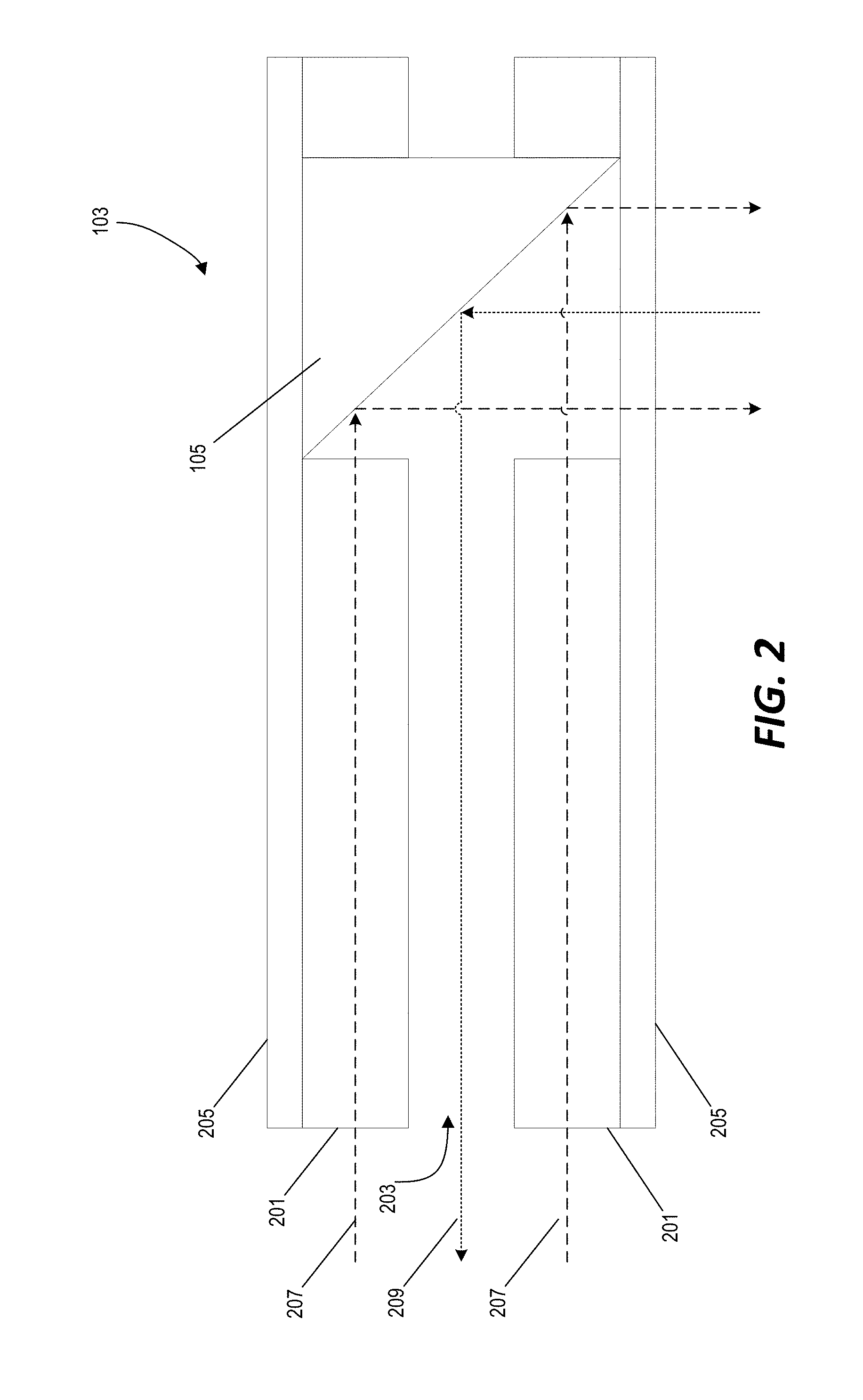
[0012] FIG. 2 is a cross-sectional view of a capillary waveguide for photoacoustic imaging in the system of FIG. 1.
[0013] FIG. 3 is a schematic diagram of light projection and sound detection mechanisms for photoacoustic imaging using the capillary waveguide of FIG. 2 in the system of FIG. 1.
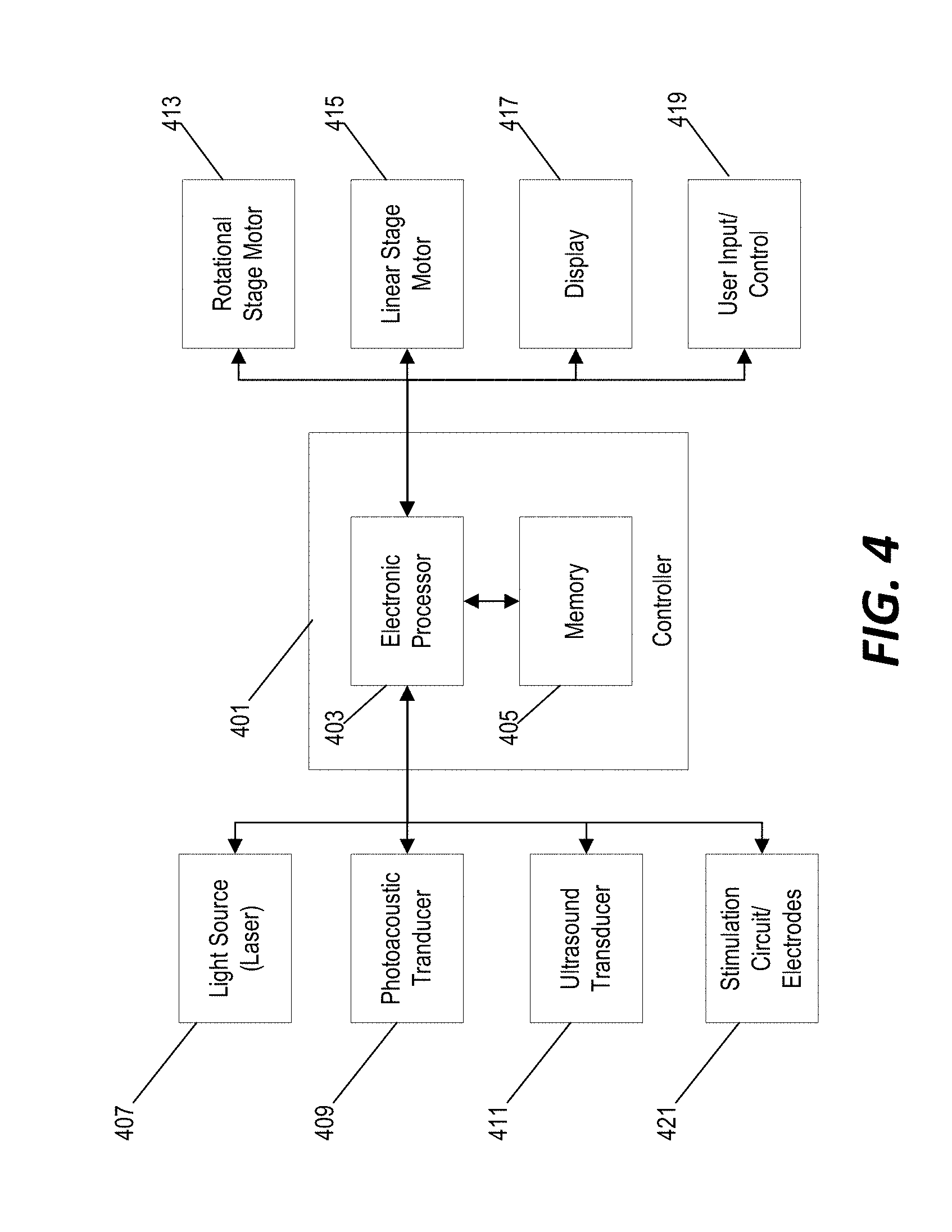
[0014] FIG. 4 is a block diagram of a control system for performing photoacoustic imaging, ultrasound imaging, and deep-brain stimulation using the system of FIG. 1.
[0015] FIG. 5A is a modular configuration of the system of FIG. 1 equipped for placement of the probe using image-based guidance.
[0016] FIG. 5B is the modular configuration of the system of FIG. 1 equipped for deep-brain stimulation after placement of the probe.
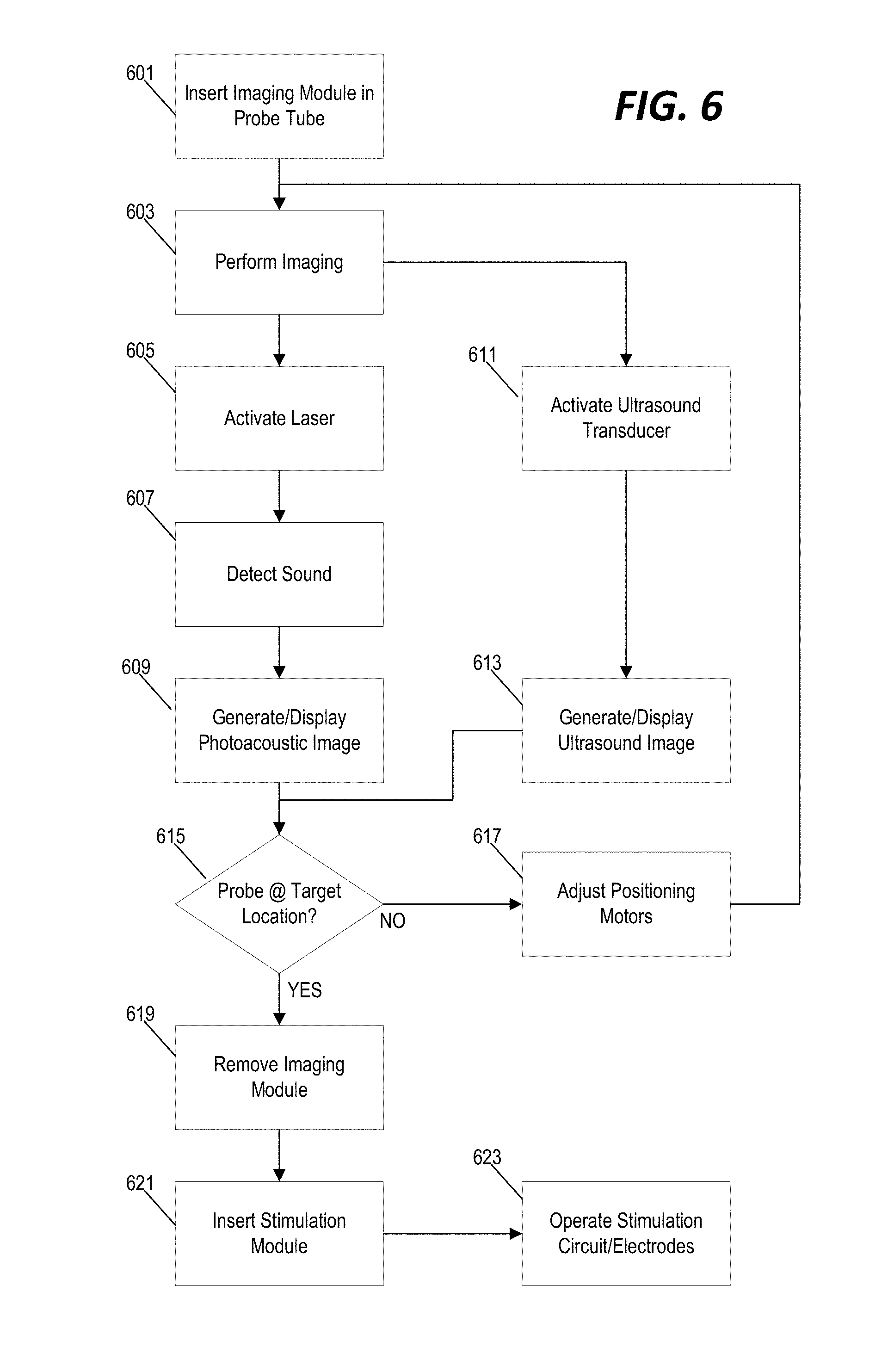
[0017] FIG. 6 is a flowchart of a method for image-based guidance and deep-brain stimulation using the system of FIG. 1 and the modular configurations of FIGS. 5A and 5B.
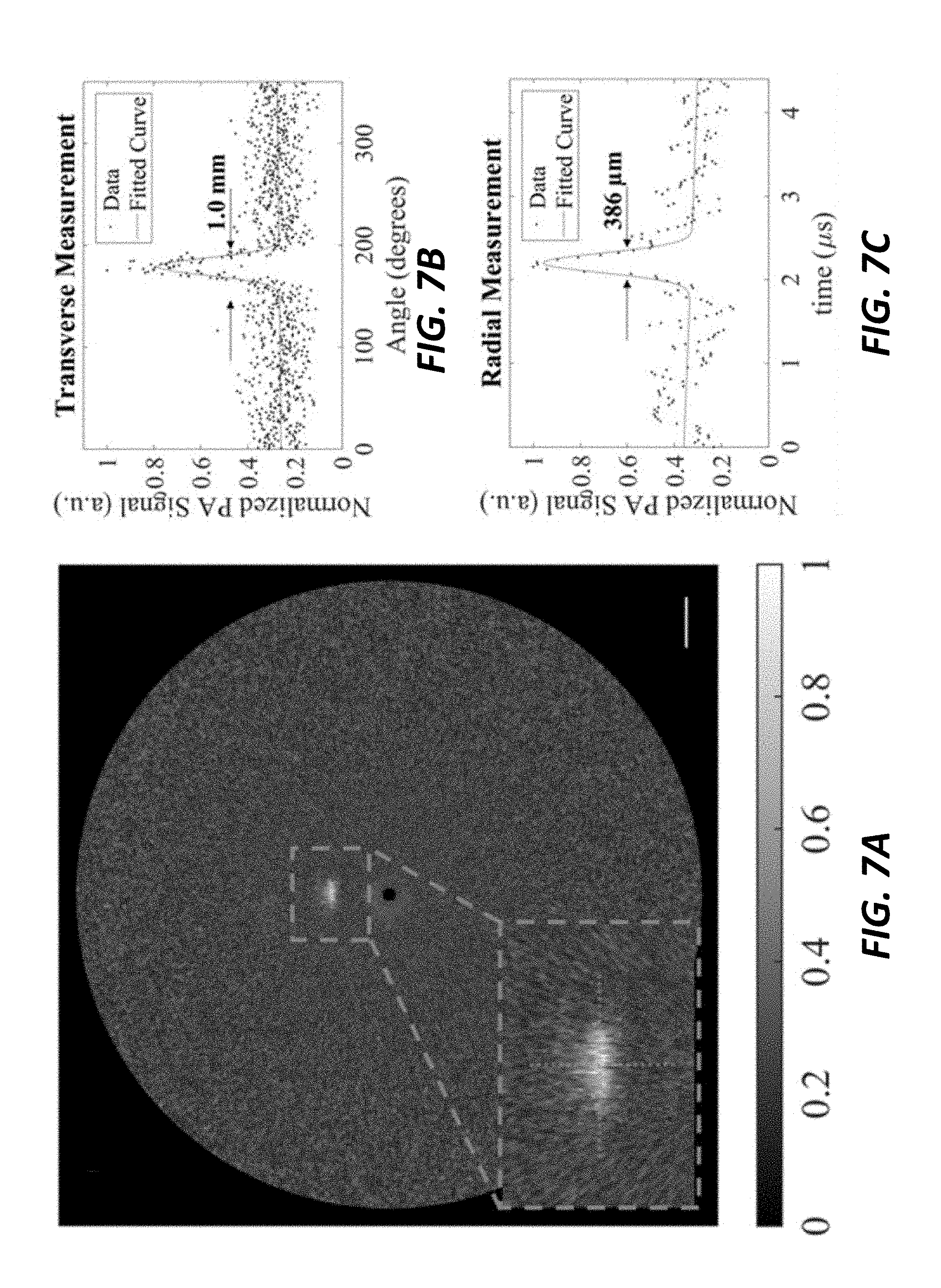
[0018] FIG. 7A is an ultrasound image generated by image data captured by the system of FIG. 1.
[0019] FIG. 7B is a graph of ultrasound image data of FIG. 7A as a function of angular position of the rotating probe demonstrating transverse resolution measurement.
[0020] FIG. 7C is a graph of ultrasound image data of FIG. 7A as a function of time as the probe is rotated demonstrating radial resolution of the peak signal in FIG. 7B.
[0021] FIG. 8A is a photoacoustic image generated by image data captured by the system of FIG. 1.
[0022] FIG. 8B is a graph of the photoacoustic image data of FIG. 8A showing the maximum amplitude at each angular position of the rotating probe.
[0023] FIG. 8C is a graph of the photoacoustic image data of FIG. 8A showing the radial data corresponding to the maximum signals of FIG. 8B.
DETAILED DESCRIPTION
[0024] Before any embodiments of the invention are explained in detail, it is to be understood that the invention is not limited in its application to the details of construction and the arrangement of components set forth in the following description or illustrated in the following drawings. The invention is capable of other embodiments and of being practiced or of being carried out in various ways.
[0025] Photoacoustic endoscopy (PAE) can be useful as a minimally invasive tool for imaging internal organs and tissues. The photoacoustic effect is generated when photons are absorbed by select targets, thus resulting in thermoelastic expansion and the creation of a subsequent acoustic wave. A transducer (often located within the endoscope itself) is used to detect acoustic waves. Previous applications of PAE have successfully provided imaging of the vasculature along the esophagus and intestines, plaque in large arteries, and the lining of the uterus. Due in part to the size of the transducer, these PAE systems typically employ the use of imaging probes with diameters on the order of a few millimeters. For certain applications where the imaging probe is required to be minimally invasive, however, further minimization is necessary. One approach may be to attempt to reduce the size of the transducer. However, because the resulting signal-to-noise ratio of the system is often dependent on the size of the transducer, the approach of reducing the size of the transducer has limitations in in-vivo applications where deep-tissue and/or low frequency transducers are required. Another notable effect of transducer miniaturization is the decreased range of working frequencies. Accordingly, imaging probes may be constrained to shallow imaging depths (e.g., no greater than a few millimeters).
[0026] Various implementations described herein circumvent these issues, in part, by providing PAE architectures that provide light transmission and sound detection on a significantly smaller size scale. For example, in some implementations, hollow optical waveguides are configured to concentrically guide both light and sound on a smaller and less-invasive size scale. Due to their material properties (i.e., borosilicate glass and quartz glass), capillaries can be used as hollow optical waveguides. These capillary tubes can be efficiently coupled to a light source such that the light travels along the glass wall of the capillary tube by total internal reflection. Transducers are coupled to the water-filled center of a hollow optical waveguide thereby enabling sound to travel several centimeters along the length of a capillary with minimal attenuation.
[0027] Furthermore, to combine the benefits of traditional side-viewing PAE with the miniaturization of hollow optical waveguides, some implementations described herein provide side-viewing photoacoustic capillary endoscopes (PCE). This design readily enables miniaturization without the need for highly specialized transducers. The water-filled hollow center of the PCE can be coupled to transducers of virtually any size or frequency. Thus, insertion of the hollow optical waveguide into tissue provides for light delivery and sound detection at distances exceeding the depth of penetration for visible light and high-frequency ultrasound. Rotation of the probe allows for a 360-degree photoacoustic reconstruction with imaging depths approaching a centimeter.
[0028] In some implementations, the PCE architecture described herein also enables integration of light delivery along with acoustic detection without obstructing either. This is accomplished through the use of an optical and acoustic combiner located externally to the PCE and up to several centimeters from the imaging window. Thus, any noise that may be generated as a result of incident light on the transducer occurs well before acquisition of the signals of interest. PAE systems with improper optical and acoustic separation may lead to ultrasound transducers being exposed to excitation light, resulting in bright rings in image reconstructions. This results in poor signal-to-noise ratio for photoacoustic signals acquired near the imaging window. With a relatively inexpensive fabrication, the PCE is an ideal candidate for a myriad of pre-clinical and clinical applications where typical PAE systems are impractical, due to their size. As a result of the efficiency of PCE in transmitting both light and sound, further imaging modalities including fluorescence and pulse-echo ultrasound imaging may still be incorporated into the device.
[0029] FIG. 1 illustrates an example of a system including a photoacoustic capillary endoscope. The system of FIG. 1 include a probe for deep-brain stimulation and is also equipped for both photoacoustic imaging and ultrasound imaging. The system 100 includes a clear plastic housing 101 with the capillary waveguide 103 positioned therein. A right-angle prism or mirror 105 is positioned at the distal end of the capillary waveguide 103 and, as described in further detail below, is configured to project light for photoacoustic imaging in a direction perpendicular to the capillary waveguide 103 and to redirect returning sound waves through the water-filled interior channel of the capillary waveguide 103. The system 100 also includes a 15 MHz ultrasound transducer 107 positioned at the distal end of the probe housing 101 beyond the distal end of the capillary waveguide 103. A signal wire 109 is communicatively coupled to the ultrasound transducer 107 and runs alongside the capillary waveguide 103 to the proximal end of the probe housing 101 where it is coupled to the image processing system (e.g., a computer as described in further detail below).
[0030] In the example of FIG. 1, the probe housing 101 includes a sound aperture 111 that allows sound waves to enter the probe housing 101 for photoacoustic imaging and allows sound waves to enter and exit the probe housing 101 for ultrasound imaging. In the example of FIG. 1, the sound aperture 111 is shown as an opening in the probe housing 101; however, as described in further detail below, in some implementations, the aperture 111 may be covered with another material (e.g., tubing) that is more sound-permeable than the probe housing 101 while also sealing the interior of the probe housing 101.
[0031] The probe housing 101 is coupled to a rotational stage 113. The rotational stage 113 includes a motor for controllably rotating the probe housing about a center axis of the probe housing 101. By controllably rotating the probe housing 101, the rotational stage 113 allows the system to capture ultrasound and photoacoustic image data in 360-degrees about the distal end of the probe housing 101 (e.g., at the sound aperture 111). The system of FIG. 1 also includes a linear stage 115 with a linear motor configured to controllably adjust a linear position of the probe housing 101 in an x and/or y direction. In this way, the linear stage 115 may be controllably operated to insert and retract the probe housing 101 into the anatomy (e.g., into the patient's skull for deep-brain stimulation).
[0032] FIG. 2 illustrates a cross-section of the capillary waveguide 103. The capillary waveguide 103 includes a hollow cylindrical tube 201 formed of borosilicate glass with an interior channel 203. In the example of FIG. 2, the borosilicate glass of the cylindrical tube 201 is 125 .mu.m thick and the diameter of the interior channel 203 is 750 .mu.m. The interior channel 203 is filled with water or another sound-conducting medium. The exterior surface of the hollow cylindrical tube 201 is enclosed in a 6 .mu.m-thick medical tubing 205. A right-angle prism 105 is positioned at the distal end of the hollow cylindrical tube 201 and enclosed in the medical tubing 205.
[0033] In this example, the hollow cylindrical tube 201 is a borosilicate glass capillary tube, B100-75-10, Sutter Instrument, and the medical tubing 205 is medical tubing 103-0552, Vention Medical. The right-angle prism 105 is provided as an aluminum-coated right angle prism (MPCH-1.0, Tower Optical). However, in other implementations, the size and material of these components may be different. Similarly, in the example of FIG. 2, the interior channel 203 of the hollow cylindrical tube 201 is filled with water. However, in other implementations, the interior channel 203 may be filled with another gaseous, liquid, or solid sound-conducting material.
[0034] Light 207 from an external source (e.g., a laser light source as described in detail below) is projected into the glass material of the hollow cylindrical tube 201 and propagates along the length of the hollow cylindrical tube 201 by total internal reflection. At the distal end of the hollow cylindrical tube 201, the light 207 exits the glass material and is reflected by the right-angle prism 105 in a direction perpendicular to the length of the hollow cylindrical tube 201. The projected light 207 causes sound 209 to be returned from the tissue material due to the photoacoustic effect. The sound 209 is also reflected by the right-angle prism 105 and propagates through the interior channel 203 along the length of the hollow cylindrical tube 201.
[0035] FIG. 3 further demonstrates the operation of the capillary waveguide in the photoacoustic imaging operation of the system of FIG. 1. In the example of FIG. 3, a light beam 301 is generated by a light source (e.g., a tunable LS-2134-LT30 Nd:YAG/Ti:Sapphire nansecond pulsed laser, Symphotic TII Corporation, operating at a 532 nm wavelength). The laser provides an excitation light with a full width half maximum (FWHM) of 12-15 ns at a pulse repetition rate of 10 Hz. Light is focused into a multimode optical fiber using a 10.times. objective with a 0.25 NA (LMH-10.times.-532, Thorlabs). In the example of FIG. 3, the optical fiber (not pictured) is coupled to the glass wall layer of the hollow cylindrical tube 201 by refocusing light onto the glass wall using a second 10.times. objective 303 with a 0.25 NA (LMH-10.times.-1064, Thorlabs). Light travels along the glass wall of the hollow cylindrical tube 201 by total internal reflection, where it is ultimately redirected by the right angle prism 105 through optically clear medical tubing 205. Light exits perpendicular to the orientation of the device, where it can induce the photoacoustic effect on a select target 307. Resulting photoacoustic signals travel through the acoustically-clear medical tubing 205 and along the water-filled core of the hollow cylindrical tube 201 to a 10 Mhz transducer 309 with a focal length of 1.27 cm, element diameter of 6 mm, and a -6 dB fractional bandwidth of 99.9% (A312S-SU, Olympus) positioned at the proximal end of the device. The distance the sound travels from the transducer to the top of the capillary tube is equal to the focal length of the transducer. A 1 mm thick glass slide 305 is positioned at a 45-degree angle to the axis of the hollow cylindrical tube 201 and enables both optical and acoustic coupling. The glass slide 305 redirects sound exiting the hollow cylindrical tube 201 toward the center of the transducer 309 while having minimal effects on the excitation light 301 coupled to the glass wall of the hollow cylindrical tube 201.
[0036] Photoacoustic signals detected by the transducer 309 are sent to an ultrasound pulser/receiver (5077PR, Olympus Inc.), where amplification is performed through a 59 dB gain and filtered with a 1 MHz high-pass filter. Data acquisition is performed with a multipurpose reconfigurable oscilloscope (NI PXIe-5170R, National Instruments Corporation) and transferred to a computer for image reconstruction. The multipurpose reconfigurable oscilloscope has built-in programmable function input/output (PFI) lines controlled by a built-in field programmable gate array (FPGA) allowing for custom triggering and synchronization of the system.
[0037] Again, FIG. 3 provides just one example of a configuration for photoacoustic imaging using a capillary waveguide. Other configurations, components, and positionings are possible. Similarly, the specific materials and components described above are only one specific example. Other system components, computing devices, amplifiers, etc. can be incorporated in other implementations.
[0038] FIG. 4 provides a simplified block diagram of a system for performing deep-brain stimulation with photoacoustic and ultrasound imaging-guidance using the system of FIG. 1. The system includes a controller 401 with an electronic processor 403 and a non-transitory computer-readable memory 405. The memory 405 stores data (e.g., image data) and instructions that are executed by the electronic processor 403 to provide certain functionality of the system. The controller 401 is communicative coupled to a light source 407 (e.g., a laser source) and a photoacoustic transducer 409. Accordingly, the controller 401 is able to operate the photoacoustic imaging by controllably operating the light source 407 and monitoring the output of the photoacoustic transducer 409. The controller 401 is also communicatively coupled to an ultrasound transducer 411 for ultrasound imaging.
[0039] The controller 401 is communicatively coupled to a rotational stage motor 413 to controllably rotate the probe housing during 360-degree imaging and is communicatively coupled to a linear stage motor 415 to controllably adjust an insertion depth of the probe housing. The controller 401 receives data from the photoacoustic transducer 409 and the ultrasound transducer 411, generates photoacoustic and/or ultrasound images from the received data, and output the generated image on a display screen 417. The controller 401 may also be coupled to a user input/control 419 through which a user may control the operation of the system. The insertion depth of the probe housing may be adjusted either manually (e.g., through the display 417 and user input control 419) or automatically based on the captured image data and, once the probe is placed at an appropriate depth proximal to a target tissue, the controller 401 regulates the operation of a stimulation circuit/electrodes 421 to provide deep-brain stimulation.
[0040] In the example of FIG. 1, both the ultrasound imaging components and the photoacoustic imaging components are provided in the same probe housing at the same time. As described above, in some implementations, the stimulation circuit and/or electrodes are also incorporated into the same probe housing with the imaging components to provide deep-brain stimulation when the probe housing is positioned at the appropriate target location. In other implementations, the system is provided as a modular configuration such that an imaging module can be selectively removed through the proximal end of the probe housing once the probe housing is positioned at a target location and a stimulation module can be inserted. FIGS. 5A and 5B illustrate one example of such a modular configuration. In the example of FIG. 5A, the photoacoustic/ultrasound module 501 is inserted into the probe housing 101 for real-time image-based guidance for placement of the probe housing 101. In FIG. 5A, the entire stimulation module 503 has been removed from the probe housing 101. Once the probe housing 101 has been placed at the appropriate target location (as confirmed via the image-based guidance), the photoacoustic/ultrasound module 501 is removed from the probe housing 101 and replaced with the stimulation module 503 as shown in FIG. 5B. In the example of FIGS. 5A and 5B, the probe housing 101 is not moved as the modules are interchanged and remains positioned at the target location for deep-brain stimulation. Accordingly, the photoacoustic/ultrasound module 501 can be used for image-based guidance to achieve proper placement of the probe housing 101 and, once, proper placement is achieved & verified, the stimulation module 503 is inserted for deep-brain stimulation at the proper target location.
[0041] FIG. 6 illustrates a method for performing deep-brain stimulation using the modular system of FIGS. 5A and 5B. First, the imaging module 501 is inserted into the probe housing 101 (step 601). As the probe housing 101 is advanced into the brain tissue, imaging is performed (step 603). For photoacoustic imaging, the laser is activated (step 605), sound generated by the photoacoustic effect is detected through the transducer 309, and photoacoustic image data is probe housing 101 is generated/displayed to the user (step 609). For ultrasound imaging, the ultrasound transducer 107 is appropriately controlled & monitored (step 611) and ultrasound images are displayed (step 613). For both imaging modalities, the probe housing is controllably rotated to provide for 360-degree imaging. The generated image data provides real-time image-based guidance for the placement of the probe housing. In some implementations, a user views the generated images and manually determines whether the probe has reached its target location (e.g., target insertion depth) (step 615). In other implementations, the system is configured to analyze the captured image data and to automatically determine whether the probe housing has reached its target location. In still other implementations, the system is configured to provide automatic guidance while prompting the user to make the final determination of whether the probe housing has reached its target location. In some implementations, image data alone is used to determine whether the probe housing has reached its target location. In other implementations, image data is used in combination with other data (e.g., electrical signals from brain electrodes as discussed above) to determine positioning of the probe housing in the anatomy.
[0042] If the probe housing has not yet reached its target location (step 615), the controller continues to operate the linear stage motors (step 617) and continues to perform imaging (step 603) until the target location is reached. Once the probe is positioned at the appropriate target location, the imaging module is removed (step 619) and the stimulation module is inserted into the probe housing (step 621). With the position of the probe housing confirmed, at least in part, by the image data, and the stimulation module in place, the controller then operates the stimulation circuit to provide deep-brain stimulation (step 623).
[0043] The example of FIG. 6 utilizes the modular component configuration of FIGS. 5A and 5B. In some implementations, the system may be configured to output a manual instruction to the user to remove and/or insert a particular system module. In other implementations, the system may be configured to automatically retract and insert individual modules into the probe housing based on a user instruction and/or an operating state of the system. For example, the system may be configured to automatically retract the imaging module and to automatically insert the stimulation module in response to automatically determining (based at least in part on the imaging data) that the probe housing has reached its target location.
[0044] Furthermore, certain functionality as illustrated in FIG. 6 may be adapted to implementations that do not include modular construction. For example, if the system is provided with the imaging components and stimulation components permanently positioned in the probe housing, the system may be configured to perform imaging, adjust the positioning of the probe, and perform the deep-brain stimulation as illustrated in the example of FIG. 6 without the instruction or automated steps for removing and/or inserting the various modules.
[0045] To demonstrate the imaging capabilities of the system described above, the imaging device is introduced into the hollow center of a cylindrical polyvinyl chloride plastisol (PVCP, M-F Manufacturing) phantom tissue and scanned from within. Line targets, embedded in the PVCP phantom tissues, are radially scanned using the methods described above. The PVCP phantom tissues are fabricated according to methods demonstrated previousl, with minor adjustments. In brief, 90 mL of PVCP is poured into a round bottom flask, submerged in an oil bath at 220 C. The mixture is allowed to heat for approximately 9 minutes while stirring under vacuum. PVCP is transferred to a glass cylinder mold with a protruding center and parallel line targets. The PVCP is allowed to remain in the mold until it reaches room temperature and solidifies. The cylindrical phantom tissue has an outer diameter of 3.8 cm, inner diameter of 3 mm, and line targets embedded. The embedded target lines consist of either carbon fiber threads with a 7.2 mm diameter are positioned approximately 1 mm from the center of the mold, or carbon fiber rods with a 254 mm diameter are positioned approximately 6.5 to 8 mm from the center. The probe housing of FIG. 1 is submerged in distilled water inside a custom built tank. A small hole, located at the bottom of the tank allows the imaging end of the capillary to be inserted into the water-filled hollow center of the phantom, which sits on the motorized stage. After each photoacoustic data acquisition the stage rotates 0.45 degrees, enabling a 360 degree 2D scan of the phantom tissue.
[0046] FIGS. 7A, 7B, and 7C illustrates photoacoustic image data acquired using the capillary waveguide of FIG. 2 with an external illumination source positioned on an opposite side of the carbon fiber thread from the capillary waveguide. The optical fiber is oriented perpendicularly to the imaging probe, aligned with the imaging window of the capillary waveguide, and positioned roughly 1 mm from the outer surface of the phantom tissue. A portion of the sound generated from the photoacoustic effect travels toward the capillary waveguide, through the acoustically clear medical tubing, where it is then redirected by the right angle prism. Sound is able to travel along the roughly 5.5 cm length of the capillary tube such that the sound exits into the water tank toward the combiner, where it is ultimately redirected toward the transducer, resulting in an A-line acquisition. This is done at 800 angular positions spanning a total of 360 degrees. A Hilbert Transform is applied to each A-line acquisition and the complex magnitude is subsequently calculated, normalized, and converted into a series of pixel values. Each processed A-line is compressed to a total of 500 representative data points by averaging clusters of numbers together, thus resulting in representative A-lines with fewer data points. Using a look-up table format, each data point is assigned a group of pixels using a weighted average, resulting in an image reconstruction, as shown in FIG. 7A. Measurements of the 7.2 mm diameter line target are performed in both the transverse and radial direction. A maximum signal is identified at each angular step, normalized, and plotted, as shown in FIG. 7B. The transverse FWHM is measured to be 1.0 mm using a Gaussian fit and a radial distance of 3 mm from the PCE. Radial resolution measurements were performed on the A-line acquired at the angular step that provided the maximum signal, as shown in FIG. 7C. Using a Gaussian fit, the radial resolution measurement shows a FWHM of 386 mm using a speed of sound in the phantom of 1400 m/s.
[0047] FIGS. 8A, 8B, and 8C illustrate photoacoustic reconstruction using internal illumination (as illustrated in FIGS. 2 and 3). In this example, a phantom was constructed with three 254 .mu.m diameter carbon fiber rods. FIG. 8A illustrates the image data captured by the photoacoustic imaging. Due to a drop in coupling efficiency between the optical fiber and the glass wall of the hollow cylindrical tube, less light is able to illuminate the targets using internal illumination. However, the carbon fiber rods are still detectable in the resulting photoacoustic image data. The reconstruction also shows an echo artifact of the carbon fiber rods. This echo emerges as a result of the 3 mm inner diameter chamber of the phantom. At each angular step of the 360 degree scan, the maximum value is calculated and plotted, as shown in FIG. 8B. In order to avoid artificial widening of the FWHM, the aforementioned echo artifacts were not included in these calculations.
[0048] The mean photoacoustic transverse FWHM is calculated to be 1.8 mm when using external illumination. Distances from the hollow cylindrical tube for each of the rods varied between 6.5 to 8.0 mm from the imaging probe. For internal illumination, the transverse FWHM is calculated to be 1.2 mm. The drop in the FWHM is likely due to the drop in excitatory light that occurred as a result of the drop in laser coupling efficiency to the glass wall of the hollow cylindrical tube. Measurements in the radial direction are performed using the singular angular position corresponding to the maximum peaks from each of the carbon fiber rods. For internal illumination, the mean FWHM in the radial direction is calculated to be 849 .mu.m. A representative signal using internal illumination is shown in FIG. 8C, which corresponds to the largest peak in FIG. 8B.
[0049] Thus, the invention provides, among other things, systems and methods for real-time in-vivo photoacoustic imaging using a capillary waveguide and a photoacoustic transducer positioned outside of the probe housing. In some implementations, the invention provides systems and methods of image-based guidance for deep-brain stimulation. Various features and advantages of the invention are set forth in the following claims.
* * * * *
D00000
D00001
D00002
D00003
D00004
D00005
D00006
D00007
D00008
XML
uspto.report is an independent third-party trademark research tool that is not affiliated, endorsed, or sponsored by the United States Patent and Trademark Office (USPTO) or any other governmental organization. The information provided by uspto.report is based on publicly available data at the time of writing and is intended for informational purposes only.
While we strive to provide accurate and up-to-date information, we do not guarantee the accuracy, completeness, reliability, or suitability of the information displayed on this site. The use of this site is at your own risk. Any reliance you place on such information is therefore strictly at your own risk.
All official trademark data, including owner information, should be verified by visiting the official USPTO website at www.uspto.gov. This site is not intended to replace professional legal advice and should not be used as a substitute for consulting with a legal professional who is knowledgeable about trademark law.