Rolling Drum For A Tobacco Industry Product Manufacturing Apparatus And Method Of Assembling Tobacco Industry Products
BRAY; Andrew Jonathan ; et al.
U.S. patent application number 16/301546 was filed with the patent office on 2019-09-19 for rolling drum for a tobacco industry product manufacturing apparatus and method of assembling tobacco industry products. The applicant listed for this patent is British American Tobacco (Investments) Limited. Invention is credited to Andrew Jonathan BRAY, Sam WHIFFEN.
| Application Number | 20190281885 16/301546 |
| Document ID | / |
| Family ID | 56369622 |
| Filed Date | 2019-09-19 |

| United States Patent Application | 20190281885 |
| Kind Code | A1 |
| BRAY; Andrew Jonathan ; et al. | September 19, 2019 |
ROLLING DRUM FOR A TOBACCO INDUSTRY PRODUCT MANUFACTURING APPARATUS AND METHOD OF ASSEMBLING TOBACCO INDUSTRY PRODUCTS
Abstract
Embodiments disclosed herein relate to a rolling drum (59 for use in a tobacco industry product manufacturing apparatus. The rolling drum has a peripheral surface (6) configured to carry a collation of rod-shaped articles. The rolling drum comprises a plurality of ridges (7) on the peripheral surface, each ridge comprising a trailing face (8) and a leading face (9). The rolling drum comprises a plurality of suction holes for retaining the collation of rod-shaped articles. The plurality of suction holes are disposed at the trailing face and the leading face of each of the ridges. Also disclosed is a rolling apparatus comprising such a rolling drum, and a machine for assembling tobacco industry products comprising such an apparatus. Also disclosed is a method of assembling tobacco industry products using such a rolling apparatus or machine.
| Inventors: | BRAY; Andrew Jonathan; (London, GB) ; WHIFFEN; Sam; (London, GB) | ||||||||||
| Applicant: |
|
||||||||||
|---|---|---|---|---|---|---|---|---|---|---|---|
| Family ID: | 56369622 | ||||||||||
| Appl. No.: | 16/301546 | ||||||||||
| Filed: | April 27, 2017 | ||||||||||
| PCT Filed: | April 27, 2017 | ||||||||||
| PCT NO: | PCT/GB2017/051177 | ||||||||||
| 371 Date: | November 14, 2018 |
| Current U.S. Class: | 1/1 |
| Current CPC Class: | A24C 5/471 20130101; A24C 5/327 20130101 |
| International Class: | A24C 5/32 20060101 A24C005/32; A24C 5/47 20060101 A24C005/47 |
Foreign Application Data
| Date | Code | Application Number |
|---|---|---|
| May 19, 2016 | GB | 1608812.2 |
Claims
1. A rolling drum for use in a tobacco industry product manufacturing apparatus, the rolling drum having a peripheral surface configured to carry a collation of rod-shaped articles, the rolling drum comprising a plurality of ridges on the peripheral surface, each ridge comprising a trailing face and a leading face, the rolling drum comprising a plurality of suction holes for retaining the collation of rod-shaped articles, wherein the plurality of suction holes are disposed at the trailing face and the leading face of each of the ridges.
2. A rolling drum according to claim 1, wherein the ridges are integral with the rolling drum.
3. A rolling drum according to claim 1, wherein the ridges are regularly distributed on the peripheral surface of the rolling drum.
4. A rolling drum according to claim 1, wherein the ridges extend along an axis parallel to a rotation axis of the rolling drum.
5. A rolling drum according to claim 1, wherein the rolling drum comprises a friction-enhancing surface on the peripheral surface between each of the ridges.
6. A rolling drum according to claim 5 wherein the friction-enhancing surface comprises a plurality of striae on the peripheral surface.
7. A rolling drum according to claim 6, wherein the plurality of striae extend along an axis parallel to a rotation axis of the rolling drum.
8. A rolling drum according to claim 5 wherein the friction-enhancing surface comprises a coating on the peripheral surface.
9. A rolling drum according to claim 5 wherein the friction-enhancing surface comprises a hard particulate matter on the peripheral surface.
10. A rolling drum according to claim 5 wherein the friction-enhancing surface comprises a sprayed coating on the peripheral surface.
11. A rolling drum according to claim 1 wherein an elongate depression is formed in the peripheral surface where the peripheral surface meets each of the trailing face and the leading face of each of the ridges.
12. A rolling drum according to claim 11 wherein the suctions holes are disposed in each of the elongate depressions.
13. A rolling drum according to claim 1 wherein a length of the peripheral surface between the ridges in a rotational direction of the rolling drum is greater than a width of the ridges in a rotational direction of the rolling drum.
14. A rolling apparatus for rolling a tipping paper around a collation of rod-shaped articles, the rolling apparatus comprising a rolling drum according to claim 1 and a roll hand configured to roll the collation of rod-shaped articles between the peripheral surface of the rolling drum and the roll hand such that a tipping paper is wrapped around the rod-shaped articles to form tobacco industry products.
15. A rolling apparatus according to claim 14, wherein the trailing faces are configured to receive a collation of rod-shaped articles upstream of the roll hand, and the leading faces are configured to receive a collation of wrapped rod-shaped articles downstream of the roll hand.
16. A rolling apparatus according to claim 14, wherein the peripheral surface of the rolling drum comprises tipping paper suction holes adapted to retain the tipping paper on the peripheral surface upstream of the roll hand.
17. A rolling apparatus according to claim 14, wherein the roll hand comprises a rolling surface over which the collation of rod-shaped articles may be rolled.
18. A rolling apparatus according to claim 17 wherein a length of the rolling surface in a rotational direction of the rolling drum is a whole number of multiples of a length of the peripheral surface between the ridges.
19. A rolling apparatus according to claim 18 wherein the length of the rolling surface in a rotational direction of the rolling drum is the same as the length of the surface between the ridges.
20. A machine for assembling tobacco industry products comprising the rolling apparatus of claim 14.
21. A method of assembling tobacco industry products using the machine of claim 20, the method comprising receiving a collation of rod-shaped articles and tipping paper on the peripheral surface of the rolling drum against a trailing face of a ridge of the rolling drum and retaining the collation of rod-shaped articles by suction through the suction holes at the trailing face, rotating the rolling drum until the roll hand contacts and pushes the collation of rod-shaped articles out of contact with the trailing edge, rolling the collation of rod-shaped articles between the peripheral surface and the roll hand such that the tipping paper is wrapped around the rod-shaped articles, and receiving the wrapped rod-shaped articles against the leading face of an adjacent ridge and retaining the wrapped rod-shaped articles by suction through the suction holes at the leading face.
22. A method according to claim 21, wherein suction is applied to retain the tipping paper on the peripheral surface of the rolling drum for a time after the collation of rod-shaped articles starts to be rolled between the peripheral surface of the rolling drum and the roll hand.
23. A tobacco industry product assembled using the machine of claim 20.
24.-26. (canceled)
Description
TECHNICAL FIELD
[0001] Embodiments of the invention relate to a drum for use in an apparatus for manufacturing tobacco industry products. Embodiments of the invention also relate to a rolling drum and a rolling apparatus for use in manufacture of tobacco industry products, in particular a rolling apparatus that rolls tipping paper around a collation of rod-shaped articles.
BACKGROUND
[0002] In the manufacture of tobacco industry products, such as cigarettes, tipping paper patches are provided with adhesive and then anchored to rod-shaped articles, such as tobacco and filter rods. The tobacco and filter rods are then rolled so that the tipping paper patch is wrapped around the tobacco and filter rods, thereby joining them together.
SUMMARY
[0003] In accordance with some embodiments described herein, there is provided a rolling drum for use in a tobacco industry product manufacturing apparatus, the rolling drum having a peripheral surface configured to carry a collation of rod-shaped articles, the rolling drum comprising a plurality of ridges on the peripheral surface, each ridge comprising a trailing face and a leading face, the rolling drum comprising a plurality of suction holes for retaining the collation of rod-shaped articles, wherein the plurality of suction holes are disposed at the trailing face and the leading face of each of the ridges.
[0004] The trailing face and leading face of each of the ridges respectively face towards and away from a direction of rotation of the rolling drum.
[0005] The ridges may be integral with the rolling drum, and may be regularly distributed on the peripheral surface of the rolling drum. The ridges may extend along an axis parallel to the rotation axis of the rolling drum.
[0006] The rolling drum may comprise a friction-enhancing surface on the peripheral surface between each of the ridges. The friction-enhancing surface may comprise a plurality of striae on the peripheral surface. The plurality of striae may extend along an axis parallel to the rotation axis of the rolling drum.
[0007] The friction-enhancing surface may comprise a coating on the peripheral surface. The friction-enhancing surface may comprise a hard particulate matter on the peripheral surface. The friction-enhancing surface may comprise a sprayed coating on the peripheral surface.
[0008] An elongate depression may be formed in the peripheral surface where the peripheral surface meets each of the trailing face and the leading face of each of the ridges.
[0009] The suctions holes may be disposed in each of the elongate depressions.
[0010] The suction holes may be provided on the trailing face and/or the leading face of each of the ridges. The suction holes may be provided where the trailing face and/or leading face of each of the ridges meets the peripheral surface of the rolling drum. The suction holes may be provided at or proximate to the point where the trailing face and/or the leading face of each of the ridges meets the peripheral surface the rolling drum. The suction holes may extend from the curved peripheral surface of the rolling drum to the trailing face and/or the leading face respectively of the ridges. In some embodiments, the curved peripheral surface of the rolling drum may meet the trailing and/or leading face of each of the ridges as defined angled junctions. Alternatively the curved peripheral surface of the rolling drum may transition smoothly in a curved manner with the trailing and/or leading face of each of the ridges. The suction holes may be provided on the curved transition between peripheral surface of the rolling drum and the trailing and/or leading face of each of the ridges. The suction holes may extend from the curved transition to the peripheral surface of the rolling drum and/or to the trailing and/or leading face of each of the ridges.
[0011] The length of the peripheral surface between the ridges in a rotational direction of the rolling drum may be greater than the width of the ridges in a rotational direction of the rolling drum.
[0012] In accordance with some embodiments described herein, there is also provided a rolling apparatus for rolling a tipping paper around a collation of rod-shaped articles, the rolling apparatus comprising a rolling drum as described above and a roll hand configured to roll the collation of rod-shaped articles between the peripheral surface of the rolling drum and the roll hand such that a tipping paper is wrapped around the rod-shaped articles to form tobacco industry products.
[0013] The trailing faces may be configured to receive a collation of rod-shaped articles upstream of the roll hand, and the leading faces may be configured to receive a collation of wrapped rod-shaped articles downstream of the roll hand.
[0014] The peripheral surface of the rolling drum may comprise tipping paper suction holes adapted to retain the tipping paper on the peripheral surface upstream of the roll hand.
[0015] The roll hand may comprise a rolling surface over which the collation of rod-shaped articles may be rolled.
[0016] The length of the rolling surface in a rotational direction of the rolling drum maybe a whole number of multiples of the length of the peripheral surface between the ridges.
[0017] The length of the rolling surface in a rotational direction of the rolling drum may be the same as the length of the surface between the ridges.
[0018] In accordance with some embodiments described herein, there is also provided a machine for assembling tobacco industry products comprising the rolling apparatus described above.
[0019] In accordance with some embodiments described herein, there is also provided a method of assembling tobacco industry products using the rolling apparatus or the machine as described above, the method comprising receiving a collation of rod-shaped articles and tipping paper on the peripheral surface of the rolling drum against a trailing face of a ridge of the rolling drum and retaining the collation of rod-shaped articles by suction through the suction holes at the trailing face, rotating the rolling drum until the roll hand contacts and pushes the collation of rod-shaped articles out of contact with the trailing edge, rolling the collation of rod-shaped articles between the peripheral surface and the roll hand such that the tipping paper is wrapped around the rod-shaped articles, and receiving the wrapped rod-shaped articles against the leading face of an adjacent ridge and retaining the wrapped rod-shaped articles by suction through the suction holes at the leading face.
[0020] Suction may be applied to retain the tipping paper on the peripheral surface of the rolling drum for a time after the collation of rod-shaped articles starts to be rolled between the peripheral surface of the rolling drum and the roll hand.
[0021] In accordance with some embodiments described herein, there is also provided a tobacco industry product assembled using the machine or the method described above.
BRIEF DESCRIPTION OF THE DRAWINGS
[0022] Embodiments of the invention will now be described, by way of example only, with reference to the accompanying drawings, in which:
[0023] FIG. 1 shows a side view of a collation of rod-shaped articles, and a tipping paper patch;
[0024] FIG. 2 shows an end view of a collation of rod-shaped articles, and a tipping paper patch, all received in the trailing edge of a ridge of a rolling drum according to an embodiment of the invention;
[0025] FIG. 3 shows an end view of the rolling apparatus according to an embodiment of the invention;
[0026] FIG. 4 shows a side view of the rolling drum according to an embodiment of the invention;
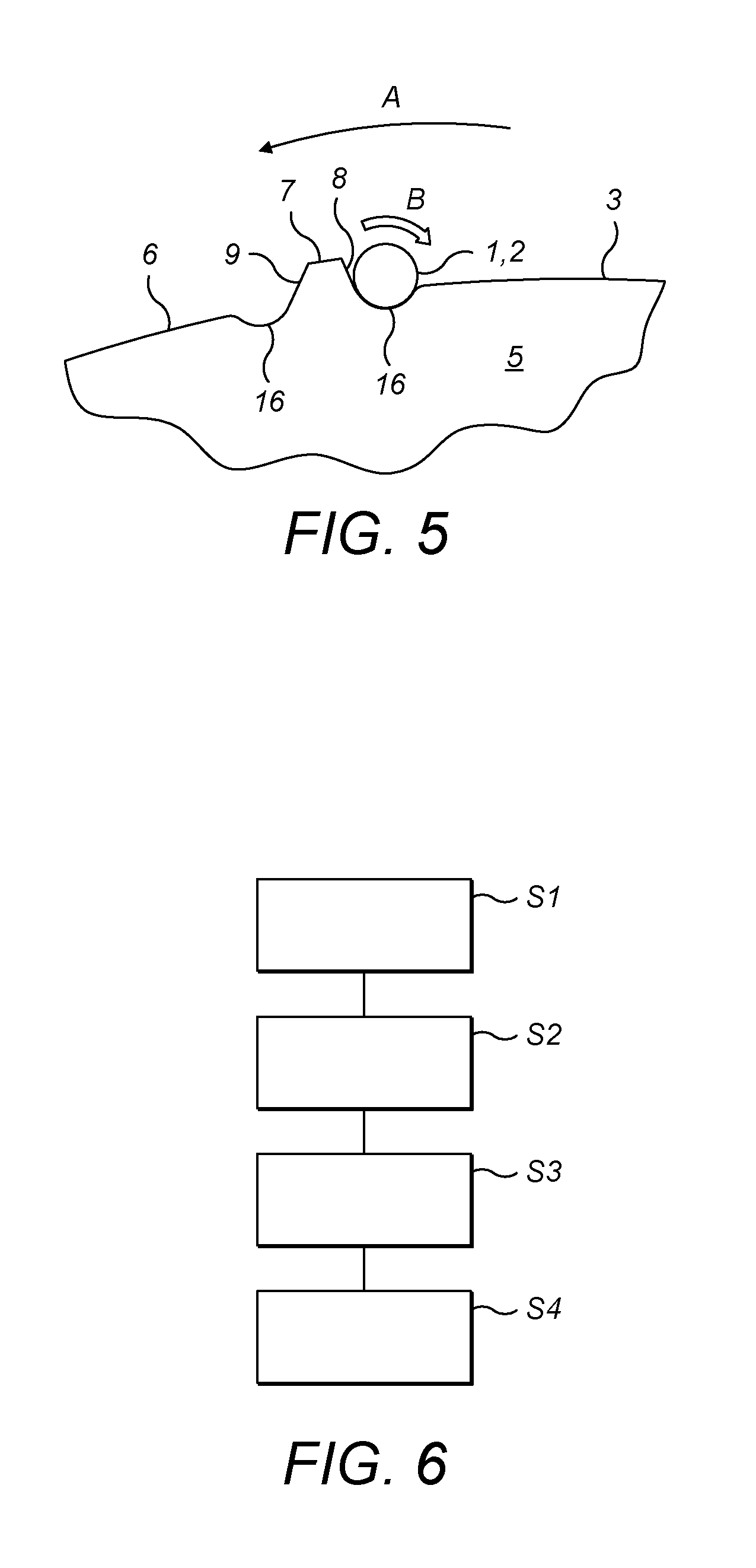
[0027] FIG. 5 shows a view similar to FIG. 2, of an end view of a collation of rod-shaped articles, and a tipping paper patch, all received in the trailing edge of a ridge of a rolling drum according to another embodiment of the invention; and
[0028] FIG. 6 shows a flow chart schematically illustrating a method of operation of a rolling apparatus comprising a rolling drum of an embodiment of the invention.
DETAILED DESCRIPTION
[0029] Referring to FIG. 1, during assembly of tobacco industry products, such as smoking article, two joined smoking articles are manufactured together by arranging two rods of smokeable material 1 at each end of a double-length rod-shaped filter component 2 to form a collation. Many such types of rods are envisaged within the scope of the invention, as explained hereafter. However, for the purpose of illustration and brevity of description, the description hereafter will discuss such rods with reference to "tobacco rods", although it should be appreciated that the invention is not limited to rods of tobacco, and may encompass any other rods for use in tobacco industry products, or smoking articles, in accordance with the definition of these terms hereafter. The tobacco rods 1 and filter component 2 are joined together by wrapping a tipping paper patch 3 about them, and then cutting through the filter component 2 to separate the two smoking articles.
[0030] Each tobacco rod 1 comprises tobacco material wrapped in a wrapper, for example a paper wrapper. In the exemplary embodiment shown, the filter component 2 comprises two filter elements each including first, second and third segments 2a, 2b, 2c. The first filter segment 2a is made of plasticized cellulose acetate through which smoke or vapour can pass. The second segment 2b comprises a tubular member made from plastic and having passages therethrough to allow smoke or vapour to pass through the filter segment 2b. The third filter segment 2c comprises a tubular member made of paper. In the collation, the filter component 2 is disposed between the two tobacco rods 1. The collation is joined using a tipping paper patch 3 that is wrapped around the filter component 2 and a part of each tobacco rod 1. FIG. 1 shows the filter component 2 disposed between the two tobacco rods 1.
[0031] Tipping paper patches 3 are provided by an apparatus (not shown) that applies adhesive to one side of a web of tipping paper and cuts the web to form patches 3. Each tipping paper patch 3 is pressed onto the collation of rods 1, 2 so that the tipping paper patch 3 is anchored to the collation of rods 1, 2 by the adhesive. In this way, when the collation of rods 1, 2 is rolled, the tipping paper patch 3 will be adhered around the circumference of the rods 1, 2, joining them together to form a smoking article assembly. The smoking article assembly can then be cut through the centre to form two smoking articles.
[0032] To wrap the tipping paper patch 3 around the collation of rods 1, 2, the collation of rods 1, 2 and the tipping paper patch 3 are rolled by a rolling apparatus 4. The rolling apparatus 4 comprises a rolling drum 5 having a peripheral surface 6 adapted to carry the collation of rods 1, 2. The peripheral surface 6 has a plurality of ridges 7. Each ridge 7 comprises a trailing face or edge 8 and a leading face or edge 9. That is, the rolling drum 5 is intended to rotate in a rotational direction (as indicated by arrow A in FIG. 2) and the leading face or edge 9 faces the direction of rotation and the trailing edge or face 8 faces away from the direction of rotation.
[0033] FIG. 2 shows the collation of rods 1, 2 and the tipping paper patch 3 when they are received in the trailing edge 8 of a ridge 7, after the tipping paper patch 3 has been anchored to the collation of rods 1, 2. Although a single ridge 7 is shown in FIG. 2, a plurality of ridges 7 are formed on the peripheral surface 6 of the rolling drum 4. Each ridge 7 extends in an axial direction across the peripheral surface 6, parallel to the rotation axis of the rolling drum 4, such that the collations of rods 1, 2 move in a direction transverse to their length when the rolling drum 4 rotates.
[0034] As shown, the anchorage between the tipping paper patch 3 and the collation of rods 1, 2 is created by a partial wrapping of the tipping paper patch 3 around the collation of rods 1, 2. The tipping paper patch 3 extends over the peripheral surface 6 of the rolling drum 5 in a trailing direction. That is, the rolling drum 5 rotates in the direction indicated by arrow A and the tipping paper patch 3 extends in the opposite direction, so that the tipping paper trails behind the collation of rods 1, 2.
[0035] As will be explained in more detail hereinafter, as the rolling drum 5 rotates in the direction of arrow A, the collation of rods 1, 2 is caused to roll from the trailing face or edge 8 and along the peripheral surface 6 of the rolling drum 5 in the direction of the arrow B shown in FIG. 2. As the collation of rods 1, 2 is rolled, the tipping paper patch 3 is wrapped around the collation of rods 1, 2, thereby joining them together. The wrapped collation is then received at the leading face or edge 9 of an adjacent ridge 7 located upstream of the initial ridge 7, and can be transferred to further apparatus.
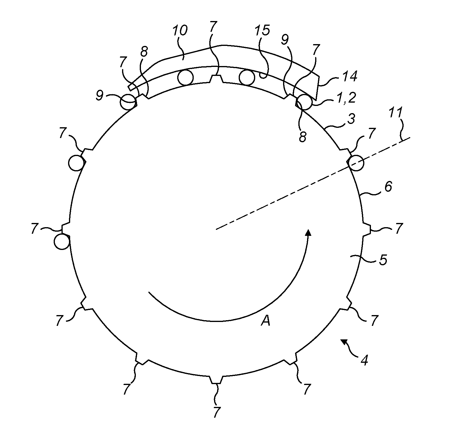
[0036] FIG. 3 shows the rolling apparatus 4 of a machine for assembling smoking articles. The rolling apparatus 4 is adapted to roll the collation of rods 1, 2 such that the tipping paper patch 3 is wrapped around the rods 1, 2 to form smoking articles. The rolling apparatus 4 comprises the rolling drum 5 and a roll hand 10. The rolling drum 5 has a plurality of ridges 7 to against which are received collations of rods 1, 2 with tipping paper patches 3 anchored thereto, as described with reference to FIG. 2. The ridges 7 are regularly distributed on the peripheral surface 6 of the rolling drum 5. The ridges 7 may be integrally formed with the rolling drum 5. The trailing face or edge 8 of each ridge 7 is adapted to receive a collation of rods 1, 2 upstream of the roll hand 10. The leading face or edge 9 of each ridge 7 is adapted to receive a collation of wrapped rods 1, 2 downstream of the roll hand 10.
[0037] The rolling drum 5 rotates in the direction of arrow A and the roll hand 10 remains stationary to cause the rolling action previously described with reference to FIG. 2. That is, the roll hand 10 causes the collation of rods 1, 2 to roll from the trailing edge 8 and along the peripheral surface 6 and towards the leading edge 9 of an upstream ridge 7, thereby wrapping the collation of rods 1, 2 with the tipping paper patch 3.
[0038] The rolling drum 4 has a receiving position, indicated by line 11. As a ridge 7 passes this receiving position 11, a collation of rods 1, 2 is transferred to the trailing edge 8 of that ridge 7 together with a tipping paper patch 3. In this example, the collation of rods 1, 2 and tipping paper patch 3 can be transferred onto the rolling drum 5 from an upstream supply drum (not shown). In other examples, the tobacco rods 1, the filter component 2 and tipping paper patch 3 may be supplied by different drums (not shown). In the exemplary embodiment, the trailing edge 8 of a ridge 7 of the rolling drum 5 receives two tobacco rods 1, the filter component 2, and a tipping paper patch 3.
[0039] The collation of rods 1, 2 is received in the trailing edge 8 of a ridge 7 in the manner described with reference to FIG. 2, that is, with the tipping paper patch 3 trailing over the peripheral surface 6 of the rolling drum 4. The rolling drum 5 includes a plurality of rod suction holes 12a, 12b and tipping paper suction holes 13 through which a suction force may be applied to hold the collation of rods 1, 2 and the tipping paper patch 3 respectively at a desired position on the rolling drum 5, as described in more detailed with reference to FIG. 4.
[0040] As the rolling drum 5 rotates, the collation of rods 1, 2 and tipping paper patch 3 are carried towards the roll hand 10. The roll hand 10 comprises a first end 14 that contacts the collation of rods 1, 2 and pushes the collation of rods 1, 2 away from the trailing edge 8 as the rolling drum 5 rotates. The roll hand 10 also comprises a rolling surface 15 over which the collation of rods 1, 2 is rolled. The rolling surface 15 of the roll hand 10 is parallel to and spaced from the peripheral surface 6 of the rolling drum 5. In other words, the rolling surface 15 is curved, with a larger radius than the peripheral surface 6 of the rolling drum 5 and centred on the axis of rotation of the rolling drum 5.
[0041] The roll hand 10 is positioned relative to the rolling drum 5 so that, once the collation of rods 1, 2 is pushed away from the trailing edge 8 and is disposed between the peripheral surface 6 of the rolling drum 5 and the rolling surface 15 of the roll hand 10, the collation of rods 1, 2 is securely held between the peripheral surface 6 and the roll hand 10. This ensures that the tipping paper patch 3 is sufficiently tightly wrapped around the collation of rods 1, 2.
[0042] The rolling apparatus 4 also includes a suction system (not shown) configured to apply suction to the suction holes 12a, 12b, 13 in the rolling drum 5 during rotation of the rolling drum 5. A suction manifold (not shown) can be used to provide the suction to the suction holes 12a, 12b during pre-defined portions of the rotation of the rolling drum 5, and to switch off the suction to the suction holes 12a, 12b in other pre-defined portions of the rotation of the rolling drum 5.
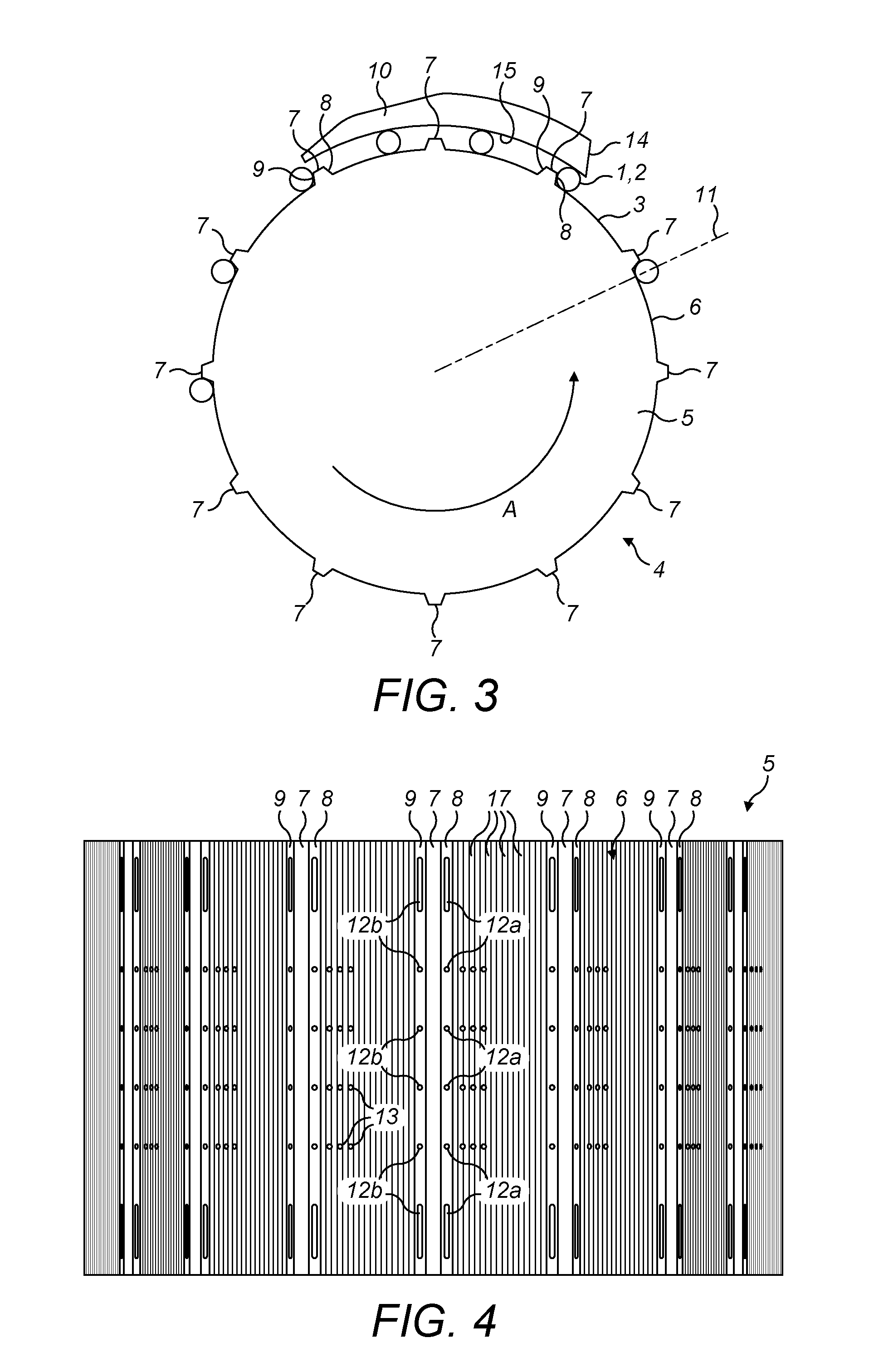
[0043] As shown in FIG. 4, the rolling drum 5 comprises a plurality of first rod suction holes 12a and a plurality of second rod suction holes 12b for retaining the collation of rods 1, 2. The first and second rod suction holes 12a, 12b are located respectively at the trailing face or edge 8 and at the leading face or edge 9 of the ridges 7. The first rod suction holes 12a are arranged in rows of suction holes 12a extending in the trailing edge 8 of each ridge 7. These rows of suction holes 12a are aligned along the peripheral surface 6 of the rolling drum 4, parallel to the rotation axis of the rolling drum 5. The second rod suction holes 12b are arranged in rows of suction holes 12b extending in the leading edge 9 of each ridge 7. These rows of suction holes 12b are aligned along the peripheral surface 6 of the rolling drum 4, parallel to the rotation axis of the rolling drum 5.
[0044] Also shown in FIG. 4, the peripheral surface 6 of the rolling drum 5 has also groups of tipping paper suction holes 13. The groups of tipping paper suction holes 13 are adapted to retain the tipping paper patches 3 on the peripheral surface 6 upstream of the roll hand 10. Each group of tipping paper suction holes 13 comprises a plurality of suction holes 13 arranged in an array on an upstream side of each trailing edge 8, so that a tipping paper patch 3 covers the tipping paper suction holes 13 upstream of each trailing edge 8.
[0045] As shown in FIG. 4, the rolling drum 5 also comprises a friction-enhancing surface configured to increase the friction between the rolling drum 5 and the collation of rods 1, 2. In the exemplary embodiment shown, the friction-enhancing surface is provided on the peripheral surface 6 between the ridges 7. In the exemplary embodiment shown, the friction-enhancing surface comprises a plurality of striae 17 formed on the peripheral surface 6. The plurality of striae 17 are arranged around the circumference of the rolling drum 5, between two consecutive ridges 7. In the exemplary embodiment, the plurality of striae 17 extend along an axis parallel to the rotation axis of the rolling drum 5. However, it will be appreciated that the invention is not intended to be limited to this configuration, as explained below. The plurality of striae 17 are provided on the peripheral surface 6 to increase the friction between the rolling drum 5 and the collation of rods 1, 2.
[0046] The operation of the rolling apparatus according to an embodiment of the invention will now be described with reference to FIGS. 1 to 4, as well as the flow-chart of FIG. 6.
[0047] As the rolling drum 5 rotates in the direction of arrow A, a ridge 7 passes the receiving position 11 and, at step S1, a collation of rods 1, 2 is transferred to the trailing edge 8 of that ridge 7 together with a tipping paper patch 3, for example from an upstream supply drum. As the rolling drum 5 rotates in the direction of arrow A, the collation of rods 1, 2 is carried in the trailing edge 8 and the tipping paper patch 3 extends from the collation of rods 1, 2 on the peripheral surface 6 of the rolling drum 5. The collation of rods 1, 2 along with the tipping paper patch 3 is carried in the trailing edge 8 towards the roll hand 10. The collation of rods 1, 2 is retained by the first rod suction holes 12a of the trailing edge 8 and the tipping paper patch 3 is retained by the tipping paper suction holes 13.
[0048] Then, at step S2, the rolling drum 5 rotates until the first end 14 of the roll hand 10 contacts the collation of rods 1, 2 and pushes the collation of rods 1, 2 out of contact with the trailing edge 8. The roll hand 10 rolls the collation of rods 1, 2 between the peripheral surface 6 of the rolling drum 5 and the roll hand 10 such that the tipping paper patch 3 is wrapped around the collation of rods 1, 2. As the collation of rods 1, 2 passes over the roll hand 10, at step S3 the collation 1, 2 is rolled over the peripheral surface 6 towards the leading edge 9 of the adjacent upstream ridge 7. At step S4, the wrapped collation of rods 1, 2 is retained by vacuum provided by the second rod suction holes 12b of the leading edge 9 downstream of the roll hand 10.
[0049] Rolling drums used in the manufacture of conventional cigarettes typically comprises a curved outer surface with flutes in the form of elongate curved recesses in which the collation of rods and tipping paper patches are received and retained. These conventional rolling drums may not be suitable for the manufacture of smoking articles such as heat-not-burn products, in which filter components may comprise rigid plastic parts. Such rigid parts may be difficult to move out from conventional flutes, or may break using conventional manufacturing apparatus which pushes the smoking article components out of the flutes. Furthermore, such conventional manufacturing apparatus which pushes the smoking article components out of the flutes may be dislodged out of alignment by such rigid parts.
[0050] The rolling drum of embodiments of the invention comprises projecting ridges provided on the peripheral surface of the rolling drum against which the collation of rods 1, 2 are retained, instead of only having recessed flutes to retain the collation of rods 1, 2 as in conventional rolling drums. That is, the ridges 7 are spaced from each other and the collation of rods 1, 2 are rolled between the ridges 7. The suction holes 12a, 12b on both the trailing and leading faces or edges 8, 9 of the ridges help ensure correct alignment and positioning of these components on the rolling drum 5.
[0051] It will be appreciated that the distance of the surface 6 of the rolling drum 5 between the ridges 7 is greater than the width of the ridges 7 in a rotational direction A of the rolling drum 5. This provides greater rolling surface on the rolling drum 5 to accommodate collations of rods 1, 2 to be rolled.
[0052] It will be appreciated that substantially the entire distance of the surface 6 of the rolling drum 5 between the ridges 7 is formed as a curve with a centre point corresponding to the axis of rotation of the rolling drum 5.
[0053] The length of the rolling surface 15 of the roll hand 10 in a rotational direction A of the rolling drum 5 may be a whole number of multiples of the length of the distance of the surface 6 of the rolling drum 5 between the ridges 7. Although not as shown in FIG. 3, the length of the rolling surface 15 of the roll hand 10 in a rotational direction A of the rolling drum 5 may be the same as the length of the distance of the surface 6 of the rolling drum 5 between the ridges 7.
[0054] It will be appreciated that the suction holes 12a are provided at the trailing faces 8 of the ridges 7, that is, the suction holes 12a may be provided, on, adjacent to or proximate the trailing faces 8 of the ridges 7. Within the scope of the invention therefore, it is intended that the suction holes 12a may be provided on the trailing faces 8 of the ridges 7, or where the trailing faces 8 of the ridges 7 meet the curved peripheral surface 6 of the rolling drum 5. Yet further, the suction holes 12a may be provided on the curved peripheral surface 6 of the rolling drum 5 where the trailing faces 8 meet the curved peripheral surface 6 of the rolling drum 5--that is, at or proximate to the point where the trailing faces 8 of the ridges 7 meet the curved peripheral surface 6 of the rolling drum 5. Yet further, the suction holes 12a may extend from the curved peripheral surface 6 of the rolling drum 5 to the trailing faces 8 of the ridges 7. In some embodiments, the curved peripheral surface 6 of the rolling drum 5 may meet the trailing faces of the ridges 7 as defined angled junctions, or alternatively may transition smoothly in a curved manner. In the latter embodiment, the suction holes 12a may be provided on the curved transition between peripheral surface 6 of the rolling drum 5 and the trailing faces 8 of the ridges 7. Also in such embodiments, the suction holes 12a may extend from the curved transition region to the peripheral surface 6 of the rolling drum 5 and/or to the trailing faces 8 of the ridges 7. All such variations are intended to comprise embodiments within the scope of the invention, in which the suction holes 12a are provided at the trailing edge or face 8 of the ridges 7. Similarly, such various configurations of suction holes 12b with respect to the leading faces or edges 9 of the ridges 7 are intended to fall within the scope of the invention.
[0055] In some embodiments, an elongate depression may be formed in the curved peripheral surface 6 of the rolling drum 5 where the curved surface 6 meets the trailing and/or leading faces 8, 9 of the ridges 7. Such an embodiment is shown in FIG. 5, illustrating such elongate depressions 16. Such elongate depressions may assist the collation of rods 1, 2 in locating against the respective trailing and/or leading faces 8, 9 of the ridges 7. The suction holes 12a, 12b may be provided in such elongate depressions 16.
[0056] It is intended within the scope of the invention that the friction-enhancing surface of the rolling drum 5 that increases friction between the rolling drum 5 and the collation of rods 1, 2 is not limited to the plurality of striae 17 of the exemplary embodiment. Other configurations of surface formations or treatment are envisaged which may be formed in or on the surface 6 of the rolling drum 5. Also, friction-enhancing surface may be applied to the surface 6 of the rolling drum 5, for example a film adhered to surface 6, or a coating sprayed onto the surface 6. Such film or coating may include grit, diamond or other hard particulates to increase friction.
[0057] As used herein, the term "upstream" will be understood to mean in opposite direction to the rotation of the rolling drum. In particular, referring to FIGS. 2 and 3, the rolling drum 5 rotates in the direction of arrow A and the term "upstream" will be understood to mean in a direction opposite to arrow A. Similarly, the term "downstream" will be understood to mean in direction of rotation of the rolling drum 5. In particular, referring to FIGS. 2 and 3, the rolling drum 5 rotates in the direction of arrow A and the term "downstream" will be understood to mean in the direction of arrow A.
[0058] As used herein, the term "tobacco industry product" is intended to include smoking articles comprising combustible smoking articles such as cigarettes, cigarillos, cigars, tobacco for pipes or for roll-your-own cigarettes, (whether based on tobacco, tobacco derivatives, expanded tobacco, reconstituted tobacco, tobacco substitutes or other smokable material), electronic smoking articles such as e-cigarettes, heating devices that release compounds from substrate materials without burning such as tobacco heating products, hybrid systems to generate aerosol from a combination of substrate materials, for example hybrid systems containing a liquid or gel or solid substrate; and aerosol-free nicotine delivery articles such as lozenges, gums, patches, articles comprising breathable powders and smokeless tobacco products such as snus and snuff.
[0059] In some embodiments, the tobacco industry product is a non-combustible smoking article. In some embodiment the tobacco industry product is a heating device which releases compounds by heating, but not burning, a substrate material. The material may be for example tobacco or other non-tobacco products, which may or may not contain nicotine. In some embodiments the heating device is a tobacco heating device.
[0060] In other embodiments the tobacco industry product is a hybrid system to generate aerosol by heating, but not burning, a combination of substrate materials. The substrate materials may comprise for example solid, liquid or gel which may or may not contain nicotine. In some embodiments, the hybrid system comprises a liquid or gel substrate and a solid substrate. The solid substrate may be for example tobacco or other non-tobacco products, which may or may not contain nicotine. In some embodiments the hybrid system comprises a liquid or gel substrate and tobacco.
[0061] The present invention is intended to encompass an apparatus and method for the manufacture of any tobacco industry product.
[0062] As used herein, the term "tipping paper" includes and material suitable for attaching the filter components to a rod of smokeable material and therefore includes any suitable type of paper, metallic foil, or other sheet material.
[0063] The drawings accompanying the various embodiments of the invention described herein are not necessarily illustrated to scale and the dimensions of certain features may be exaggerated for ease and clarity of illustration.
[0064] In order to address various issues and advance the art, the entirety of this disclosure shows by way of illustration various embodiments in which the claimed invention(s) may be practiced and provide for a superior rolling apparatus for assembling smoking articles. The advantages and features of the disclosure are of a representative sample of embodiments only, and are not exhaustive and/or exclusive. They are presented only to assist in understanding and teach the claimed features. It is to be understood that advantages, embodiments, examples, functions, features, structures, and/or other aspects of the disclosure are not to be considered limitations on the disclosure as defined by the claims or limitations on equivalents to the claims, and that other embodiments may be utilised and modifications may be made without departing from the scope and/or spirit of the disclosure. Various embodiments may suitably comprise, consist of, or consist essentially of, various combinations of the disclosed elements, components, features, parts, steps, means, etc. In addition, the disclosure includes other inventions not presently claimed, but which may be claimed in future.
* * * * *
D00000
D00001
D00002
D00003
XML
uspto.report is an independent third-party trademark research tool that is not affiliated, endorsed, or sponsored by the United States Patent and Trademark Office (USPTO) or any other governmental organization. The information provided by uspto.report is based on publicly available data at the time of writing and is intended for informational purposes only.
While we strive to provide accurate and up-to-date information, we do not guarantee the accuracy, completeness, reliability, or suitability of the information displayed on this site. The use of this site is at your own risk. Any reliance you place on such information is therefore strictly at your own risk.
All official trademark data, including owner information, should be verified by visiting the official USPTO website at www.uspto.gov. This site is not intended to replace professional legal advice and should not be used as a substitute for consulting with a legal professional who is knowledgeable about trademark law.