Real-time Face And Object Manipulation
Yuan; Hang ; et al.
U.S. patent application number 15/917441 was filed with the patent office on 2019-09-12 for real-time face and object manipulation. The applicant listed for this patent is Apple Inc.. Invention is credited to Ming Chen, Chris Y. Chung, Jae Hoon Kim, Hsi-Jung Wu, Hang Yuan, Jiefu Zhai, Dazhong Zhang, Xiaosong Zhou.
| Application Number | 20190279681 15/917441 |
| Document ID | / |
| Family ID | 67843343 |
| Filed Date | 2019-09-12 |


| United States Patent Application | 20190279681 |
| Kind Code | A1 |
| Yuan; Hang ; et al. | September 12, 2019 |
REAL-TIME FACE AND OBJECT MANIPULATION
Abstract
Techniques are presented for modifying images of an object in video, for example to correct for lens distortion, or to beautify a face. These techniques include extracting and validating features of an object from a source video frame, tracking those features over time, estimating a pose of the object, modifying a 3D model of the object based on the features, and rendering a modified video frame based on the modified 3D model and modified intrinsic and extrinsic matrices. These techniques may be applied in real-time to an object in a sequence of video frames.
| Inventors: | Yuan; Hang; (San Jose, CA) ; Zhai; Jiefu; (San Jose, CA) ; Chen; Ming; (Cupertino, CA) ; Kim; Jae Hoon; (San Jose, CA) ; Zhang; Dazhong; (Milpitas, CA) ; Zhou; Xiaosong; (Campbell, CA) ; Chung; Chris Y.; (Sunnyvale, CA) ; Wu; Hsi-Jung; (San Jose, CA) | ||||||||||
| Applicant: |
|
||||||||||
|---|---|---|---|---|---|---|---|---|---|---|---|
| Family ID: | 67843343 | ||||||||||
| Appl. No.: | 15/917441 | ||||||||||
| Filed: | March 9, 2018 |
| Current U.S. Class: | 1/1 |
| Current CPC Class: | G11B 27/031 20130101; G06K 9/00255 20130101; G06K 9/00281 20130101; G06T 19/20 20130101; G06K 9/00201 20130101; G06T 2207/10016 20130101; G06K 9/00288 20130101; G06T 2219/2021 20130101; G06T 2207/30201 20130101; G06T 5/006 20130101; G06T 7/74 20170101 |
| International Class: | G11B 27/031 20060101 G11B027/031; G06T 5/00 20060101 G06T005/00; G06T 7/73 20060101 G06T007/73; G06T 19/20 20060101 G06T019/20; G06K 9/00 20060101 G06K009/00 |
Claims
1. An image processing method, comprising: for a frame of a video source: estimating a pose of an object of a selected type from the source video frame; modifying an estimated 3D model of the selected type of object; deriving a first matrix based on a desired focal length; deriving a second matrix based on the pose and the desired focal length; and rendering a modified video frame based on the first matrix, the second matrix, and the modified 3D model.
2. The method of claim 1, wherein the first matrix is an modified intrinsic matric, the second matrix is a modified extrinsic matrix, and the rendering comprises rendering a projection of the 3D model based on the modified intrinsic matrix and the modified extrinsic matrix.
3. The method of claim 1, further comprising: extracting features of the object from the source video frame; and estimating the 3D model of the selected type of the object based on the extracted features.
4. The method of claim 1, further comprising: deriving a source intrinsic matrix from an estimated source focal length; and deriving a source extrinsic matrix from the pose.
5. The method of claim 1, wherein the object is a face and the 3D model is a face model, and further comprising for the frame of source video: adjusting the 3D model according to user input.
6. The method of claim 1, wherein features are extracted and a pose is estimated from at least one previous frame of the video source, and further comprising for the frame of the video source: filtering the extracted features for temporal consistency; and filtering the estimated pose for temporal consistency.
7. The method of claim 6, further comprising: filtering the estimated 3D model for temporal consistency, and filtering a background of the source video frame for temporal consistency.
8. The method of claim 1, further comprising for the frame of source video: further modifying the 3D model based on selected model alterations, wherein the selected alterations include a shape modification or pose change.
9. An image processing method comprising: detecting an object of a selected type in a video frame; extracting features of the detected object; matching the detected object to a profile in a database; tracking the features over a plurality of frames; validating the features; and modifying the video frame based on a selected object alteration associated with the profile.
10. The method of claim 9, further comprising: when there is no match for the detected object in the database, create a new profile, where the new profile includes a 3D model of the object, and includes object alterations specified by user input.
11. The method of claim 10, further comprising: recognizing the object in images from a photo or video library; and generating the 3D model of the object based in part on the images from the photo or video library.
12. The method of claim 9, wherein the profile includes a 3D model of the object, and further comprising modifying the 3D model to produce the selected object alteration.
13. The method of claim 9, wherein the selected type of object is a face, and matching the detected object includes face recognition.
14. The method of claim 9, wherein the validating the features includes filtering the tracked features for temporal consistency.
15. The method of claim 9, wherein the selected object alteration includes a shape modification or a pose change.
16. The method of claim 9, further comprising: recognizing the detected object as the same object detected in a previous video frame; and wherein the tracking tracks features of detected objects recognized as the same object detected in the previous video frame.
17. An image processing system, comprising: a memory; and a controller that, for a frame of a video source: estimates a pose of an object of a selected type from the source video frame; modifies an estimated 3D model of the selected type of object; derives a first matrix based on a desired focal length; derives a second matrix based on the pose and the desired focal length; and renders a modified video frame based on the first matrix, the second matrix, and the modified 3D model.
18. The system of claim 17, wherein the first matrix is an modified intrinsic matric, the second matrix is a modified extrinsic matrix, and the rendering comprises rendering a projection of the 3D model based on the modified intrinsic matrix and the modified extrinsic matrix.
19. The system of claim 17, wherein, for the frame of source video, the controller further: extracts features of the object from the source video frame; and estimates the 3D model of the selected type of the object based on the extracted features.
20. The system of claim 17, wherein the controller further: deriving a source intrinsic matrix from an estimated source focal length; and deriving a source extrinsic matrix from the pose.
21. The system of claim 17, wherein the object is a face and the 3D model is a face model, and wherein, for the frame of source video, the controller further: adjusts the 3D model according to user input.
22. The system of claim 17, wherein features are extracted and a pose is estimated from at least one previous frame of the video source, and wherein, for the frame of the video source, the controller further: filters the extracted features for temporal consistency; and filters the estimated pose for temporal consistency.
23. The system of claim 17, wherein, for the frame of source video, the controller further: filtering the estimated 3D model for temporal consistency, and filtering a background of the source video frame for temporal consistency.
24. The system of claim 17, wherein, for the frame of source video, the controller further: further modifying the 3D model based on selected model alterations, wherein the selected alterations include a shape modification or pose change.
25. A computer readable memory comprising instructions that, when executed by a processor, cause, for a frame of a video source: estimating a pose of an object of a selected type from the source video frame; modifying an estimated 3D model of the selected type of object; deriving a first matrix based on a desired focal length; deriving a second matrix based on the pose and the desired focal length; and rendering a modified video frame based on the first matrix, the second matrix, and the modified 3D model.
Description
BACKGROUND
[0001] Cameras have become small, lightweight, and almost ubiquitous. These small cameras often have a short focal length, and are often used to capture images of objects close to the camera, such as selfie images. The combination of short focal length and small distance between an object and a camera can create a projection of the object in captured images that may seem distorted, especially in comparison to images of the object captured with longer focal lengths and longer distances to the camera. The short focal length of a wide-angle lens may create a type of lens distortion called barrel distortion. The short distance to the center of an object relative to the differences in distance to different points on an object may seem to distort the projection as portions of the object closer to the camera appear larger than portions of the object further from the camera.
[0002] For example, a selfie photo or video is a self-portrait of the person holding the camera. The object in a selfie image is typically the face of the person who is holding the camera in their hand at arm's length, or less, from their face. Furthermore, selfie images are typically taken with a camera on the front face of a smartphone so that the selfie taker can see their own image on the smartphone camera while they take the selfie. Cameras on the front face of a smartphone typically have a shorter focal length than the higher-quality cameras on the back face of a smartphone. This combination of a short focal length of a front-face camera with short arm's length distance between camera and face produce images with a projection that may appear distorted, particularly in comparison to non-selfie images of the same face taken at a longer distance by the back-face camera on the same smartphone. With a nose of a face centered and close to a camera, the nose will appear large relative to the ears of the same face because the nose will be closer to the camera, and also because barrel distortion will enlarge items in the center of the image while shrinking items toward the edges of an image.
BRIEF DESCRIPTION OF THE DRAWINGS
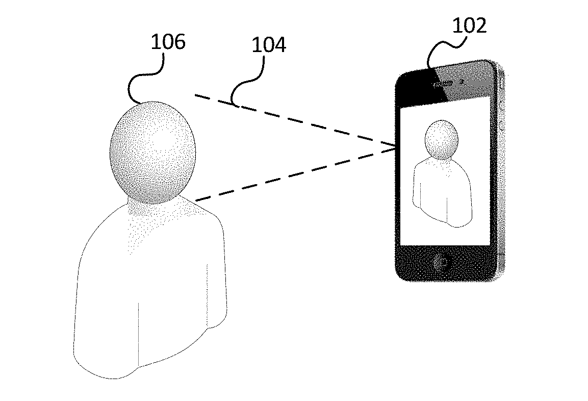
[0003] FIG. 1A depicts an example of an object being captured by an image capture system.
[0004] FIG. 1B depicts an example image capture system.
[0005] FIG. 2 depicts example projections of an object onto an image plane.
[0006] FIG. 3A is an example flowchart for modifying video images.
[0007] FIG. 3B is an example flowchart for modifying video images.
[0008] FIG. 4 is an example flowchart for modifying video images.
DETAILED DESCRIPTION
[0009] This application describes techniques for editing images, including real-time editing of three-dimensional (3D) objects, such as faces, in captured video. The techniques include extracting features of an object, of a predetermined type, such as a face, from a source video frame, and estimating a pose of the object. A 3D model of the predetermined type may be modified based on the extracted features. Intrinsic and extrinsic matrices may be derived from a desired camera focal length and the pose of the object. A modified video frame can then be generated by rendering a modified version of the object based on the intrinsic and extrinsic matrices, and the modified 3D model of the object. In some aspects, extracted features can be filtered for temporal consistency, and areas of the source image frame that do not include the object may be extended or otherwise modified to accommodate the modification of the object. In some aspects, the source video frame is modified by two-dimensional (2D) morphing based on projections of feature point locations of the modified 3D model.
[0010] In some aspects, an object detected in video can modified for aesthetic reasons, such as alteration of shape or pose, and may be based on user input. For example, an object that is a face may be perceived as more beautiful if eyes are enlarged or the nose is reduced in size. Such aesthetic modifications may be applied to captured video automatically according to a pre-determined profile when a particular object is recognized in a frame of video. Such techniques may include detecting an object of a predetermined type in a video frame; extracting features of the detected object; matching the detected object to a profile in a database; tracking the features over a plurality of frames; validating the features; and modifying the video frame based on a predetermined object alteration associated with the profile.
[0011] FIG. 1A and depicts an example of an object being captured by an image capture system. As depicted, camera system 102 may capture images of object 106 that are within the field of view 104 of the camera system 102. In the example of FIG. 1A, the camera system 102 is on the front face of a smartphone with a wide-angle lens, and an object captured is the face of a person, resulting in selfie-style images.
[0012] FIG. 1B depicts an example image capture system. Camera system 102 comprises a lens system 122 with field of view 104 and image sensor 124, as well as computer memory 130, controller 132, storage 126, and network connection 128, all interconnected via computer bus 134. Images captured by sensor 124 may be stored in storage 126 and analyzed and modified by controller 132 while in memory 130. Modified images may be stored for later use in storage 126 or transmitted real-time to a viewer via network 128. Controller 132 may control lens system 122 and sensor 124. In some aspects, and a focal length of lens system 122 may be estimated or set 132. Persons skilled in the art appreciate that while storage 126 and memory 130 are depicted as separate components in FIG.1B, in other aspects, functionalities of storage 126 and memory 130 may be in a single component.
[0013] FIG. 2 depicts example projections of an object onto an image plane. An object in an original position 202 is depicted at a first distance from image plane 208 along the z-axis. A projection of the object onto the image plane 208 with focal length 210 results in projection 206 of the object on image plan 208. A camera with focal length 210 would result in a captured image of the object in the original position 202 as projection 206. Such a captured image may be modified according to a desirable focal length 212, by moving the object from the original position 202 to the compensated position 204 at a longer distance from image plane 208 along the z-axis. Moving the object from position 202 to position 204 may result in a projection of the object onto image plan 208 with desirable focal length 212 that is the same or similar size as the projection 206 of from the object in the original position 202. In alternate aspects (not depicted), the projection of an object moved from the original position 202 may result in a projection on the image plane 208 that is either larger or smaller than projection 206 from the original position. An intrinsic matrix and extrinsic matrix can be used to create a projection of the 3D model onto the image plane. An intrinsic matrix may be determined based on camera parameters, while an extrinsic matrix may be based on a pose (orientation) and position of the 3D object.
[0014] For example, if an image of the object in position 202 is captured with a wide-angle camera having focal length 210, some lens distortion can be removed from the captured image by modifying the projection 206 to appear as if the object were captured at compensated position 204 with a camera having desirable focal length 212. In order to modify the captured image, a pre-existing 3D model of the object can be fit to match the captured projection 206. An intrinsic matrix can be created using the desirable focal length, and an extrinsic matrix can be created using the compensated position 204 of the object. The 3D model can then be projected onto the image plan to generate a projection to replace the projection of the object in the original image. In one aspect, portions of the original image that do not include the object remain the same. In another aspect, portions of the original image outside the object may also be modified, for example, when altering the shape of the object reveals or obscures a portion of the image that was not revealed or obscured in the unmodified original image.
[0015] FIG. 3A is an example flowchart for modifying video images. For each captured frame i (box 350), a model of an object in frame i is built (box 360). For example, a new model is created or pre-existing model may be modified. In some cases, a preexisting generic model, such as a model of a generic human face or other object, may be customized to match features detected in the captured frame i. In other cases, a preexisting model that is already tailored to the specific object, for example based on data in one or more frames other than frame i, may be further tailored to current frame i using, for example, features extracted from current frame i. The model of the object is then modified to improve visual effects, for example by reducing lens distortion, or altering the same of the object according to improve a perceived beauty of the object, such as may be specified by user input (box 364). The modified model is then used to render a modified frame i, for example by creating a new rendering of the object, and replacing the captured rendering of the object in captured frame i with the new rendering of the object while leaving substantially intact the background of the object in captured frame i.
[0016] FIG. 3B is an example flowchart for modifying video images. Process 300 may be repeated for each captured frame i of a video sequence. Dashed boxes are optional, such as boxes 302, 308, 310, 312, and 314. In optional box 302, a focal length of the camera capturing the video may be estimated. In some aspects this may vary per frame as the camera lens system is zoomed or focused, and the estimate may be based on data obtained directly from the lens systems or based on control signals sent to the lens system. In other aspects, a camera's focal length may be fixed and known, and hence not estimated per frame. A source intrinsic matrix may be determined based on an estimated focal length.
[0017] Boxes 304-312 build or modify a model of an object in captured frame i. In box 304, features of an object in the captured frame i are extracted. Features may include 2D locations in the captured frame i of visually distinct features. For example, if the object is a face, extracted features may include locations of facial features, such as the locations of the tip of the nose, the corners of the eyes, and the corners of the mouth. In box 306, a 3D shape and a pose of the object may be estimated. If a pose or 3D shape for a previous frame exists, box 306 may estimate the pose and/or 3D shape for frame i based in part of the pose and/or 3D shape of the previous frame. A pose may include the 3D angular position of the object. The pose estimated from captured frame i may be used to derive a source extrinsic matrix in optional box 308. The 3D shape estimated in box 306 may be, for example, a 3D wireframe model. If a pose or 3D shape estimate already exist for a previous captured frame and stored in, for example, storage 126 and/or memory 130, a current pose or 3D shape may be estimated based on the pre-existing pose or shape estimates.
[0018] In box 310, the extracted features may be validated and adjusted for temporal consistency with features extracted in other frames (before or after frame i). For example, the same features may be tracked from frame to frame, and the location of corresponding features may be filtered to smooth the motion of the extracted features. Additionally, in box 310, the 3D shape, such as a 3D wireframe model, may also be validated and adjusted for temporal consistency. Adjustments for temporal consistency may reduce noise in the estimates of features and 3D model for a current frame, and such adjustments may also reduce the effect of noise in prior estimates of the features and 3D models. Consequently, over time, new extracted features may appear, and previous extracted features may disappear. Adjustments in optional box 310 may address new and disappearing features. Validation of features and 3D model in box 310 may include validation techniques of box 422 of FIG. 4, described below. For example, if the features or 3D model for the current frame is not validated, various techniques may be used to mitigate the visual effects of invalid features or model. For example, the current frame may be dropped (e.g., not adjusted, not used in future processing, and/or not displayed), or a new set of features or new 3D model may be estimated using alternative means. In the situations where no object is detected in the current frame, pixel-level techniques maybe used without estimates of features or a 3D model to modify the current frame to prevent sudden visual temporal changes without dropping the frame.
[0019] Areas of a current frame outside the object may also be modified, for example, when altering the shape of the object reveals or obscures a portion of the current frame that was not revealed or obscured in the unmodified current frame. Pixel-level modification techniques may be provided to solve this problem of revealed or obscured background. In another aspect, a background of the object may also be independently tracked over time such that the background hidden behind the object in the current frame may be constructed from the background of other frames where the object does not obscure the same background area, for example because the object tin the other frames may be at a different location in the frame or a smaller size.
[0020] In box 312, a preexisting model of an object of known type may be modified based on the extracted features. For example, the extracted features of an object believed to be a face may be mapped to a generic 2D or 3D wireframe model of a face, and then the corners of the generic wireframe model may be altered based on the extracted features. For example, the modification of a generic face may include widening the space between the eyes or enlarging the nose to match extracted features determined to correspond to corners of the eyes or tip of the nose. If a pre-existing model of the particular object in captured frame i exists, for example as a result of modifying a generic model based on previous frames, then in box 312 the pre-existing model of the particular object in captured frame i may be modified to account for changes to the object (for example, changes since a previous frame).
[0021] In some aspects, the model may include attributes of an object other than feature locations. For example, a face model may include expression attributes, which can include a degree of smile attribute that relates to the width between corners of the mouth. Alternatively or additionally, persons skilled in the art will appreciate that the estimated 3D model may include any other suitable attributes. One or more of these attributes can be adjusted in real time as the video images are being captured and processed.
[0022] Boxes 314-316 modify the previously built model of the object to render a more desirable image in box 320. In optional box 314, the 3D model may be further modified according to user input either in real-time or as previously stored options (as further described in box 430 of FIG. 4). In other words, the 3D model may be modified by changing elements that do not necessarily correspond to estimated 2D features. For example, eyes in a face model may be enlarged by moving feature locations corresponding to the corners of the eyes. As another example, the degree of smile may be increased. In some cases, such user-specified modifications may enhance or exaggerate certain facial features or characteristics.
[0023] In box 316 a modified intrinsic and extrinsic matrix may be derived. For example, a modified intrinsic matrix may be based on a desired focal length, and a modified extrinsic matrix may be derived corresponding to the desired focal length. For example, as explained above regarding FIG. 2, a modified extrinsic matrix may be based on a compensated location along the z-imaging axis that accounts for the change in focal length, such that the compensated location will produce a projection of the object in the image plane having a size in the image plane similar to the projection size of the object at the original location captured with the original focal length.
[0024] Finally, in box 320, a modified frame i may be rendered based on projecting the modified object model onto the image plane using the modified intrinsic matrix and modified extrinsic matrix. Rendering may be done in various ways, such as by ray-tracing a 3D model, or 2D morphing of the original object image. In 3D ray-tracing, the modified 3D model is ray-traced onto the image plan with the modified intrinsic and extrinsic matrices, and then pixels in the captured image containing the object are replaced with the newly ray-traced rendering of the object. In 2D morphing, the original image of the object may be tessellated according to 2D locations of extracted features. The modified 3D model and modified intrinsic and extrinsic matrices may be used to determine new locations for the extracted 2D features. The tessellated original 2D image of the object can be then be morphed to match the new 2D feature locations.
[0025] FIG. 4 is an example flowchart for modifying video images. Real-time modification of a rigid 3D object such as a face, including, for example, modification for beautification or other special visual effects, may be realized through a combination of object recognition, object detection, object feature extraction and tracking, 3D object modeling, optimization and morphing/rendering. If the object is a face, modification may include face recognition, face detection, facial feature extraction and tracking, and 3D face modeling. FIG. 4 depicts a flowchart for modifying a face.
[0026] In FIG. 4, a camera system such as camera system 102 of FIGS. 1A and 1B may capture a frame (box 402). If the system has not been initialized (box 404), an initialization process may begin at box 412. Prior to modifying images of the object, an initialization process will invoke an object detector (box 412). If an object is detected (box 414), features of the object will be detected (box 416), for example for tracking features across future frames, and a search may be performed for the detected object in an object database (420).
[0027] If it is a new object that does not exist in the database (box 424), an initialization process may be conducted to establish a new object profile (boxes 426, 428) that may include a 3D object model for the new object and modification preferences (430) such as beautification parameters or other desired effects desired. In some aspects, modification preferences may be specified by a user of the modification system. For example, each instance of an object (such as each face) may be assigned a unique ID using feature detection (box 416) to determine object features (box 418) and face or object recognition technology. In other aspects, object recognition techniques may identify or assign a unique object ID without reference to the features detected in box 416. At the same time, a 3D model can be quickly obtained for the object. In some aspects, existing images and videos stored in system 102 or found on an external server may be used instead of or in addition to the incoming frames to obtain the 3D model for the object.
[0028] A user can then provide a few options as to how she or he wants to modify her or his face or other object (box 430). Modification options may include, for example, shape manipulation or perspective change. The initialization process may be completed by saving the modification options as morphing parameters (box 428).
[0029] Later, when an object with an existing profile appears in an incoming frame (box 402) after initialization, the corresponding unique object ID may be retrieved from the database by an object or face recognition process (box 406) together with the saved object model and user-specified morphing parameters. If the same object is found as in a previous frame, the features of the face or other object are tracked over time in frames containing the same face (box 410) to obtain temporally consistent facial features.
[0030] On the other hand, if the recognized object cannot be tracked in the current incoming frame or is not the same as a previous frame (box 408), the initialization process described above is started at box 412. The object detector (box 412) may be called and, if an object is found (box 414), the feature detector (box 416) may provide a new set of object features for subsequent operations and frames, and object database initialization may continue as described above from box 420.
[0031] Object or facial features (box 418) are validated (box 422). Validation may involve any number of suitable metrics. Validation may include, for example verifying that the amount of change (the amount of motion) of a feature tracked in 2D pixel space of the incoming images is smooth. Alternately, or in addition, the features tracked in the incoming 2D images may be mapped to features of a 3D model. For example, 2D feature locations in 2D space may be mapped to 3D vertex locations of a 3D wireframe model of the object or face. Validation may ensure, alternately or in addition to 2D smoothing, that motion or other change of 3D model features is smooth. As another example, in addition to smoothness, validation may determine whether the derived features may result in a shape that looks like the tracked object. Typically, machine learning techniques may be used, for example, to gauge the likelihood that the detected features are reliable. As yet another example, the validation process may address features that appear or disappear.
[0032] If the validation process fails for an incoming frame, the frame may be dropped and not modified, and the process continues with the next incoming frame (box 402). If the tracked features are validated, the object may be modified based on retrieved user-specified morphing parameters (box 432) to produce a modified frame (box 434) comprising the modified object. In an aspect, the portions of the incoming frame that did not include the recognized object may not be substantially changed. The object modification process may, for example comprise the object model modification of FIG. 3B box 314, and modified frame (box 434) may be produced using rendering process FIG. 3B box 320, which are described above.
[0033] In an alternate aspect, pixel-level techniques may be used to construct a modified frame instead of dropping a frame. For example, if validation in box 422 fails, or if an object is not detected in box 414, instead of dropping the frame, pixel-level techniques may be used to construct a modified frame. In cases where a previous frame has already been modified, and either validation or object detection fails for a current frame, presentation (or other use) of the current unmodified frame following previous modified frames may create undesirable visual artifacts. Similarly dropping a frame may create an undesirable visual artifact. In these cases, a pixel-level technique for modification of the current frame may employ parts of the 3D model or other understanding of the current or previous frame content along with pixel-level techniques to render a modified current frame without rendering based on the complete 3D model, as in box 320. Examples of the understanding of a frame that is not the complete 3d model include: an understanding of the separation between, or locations of, the object and the background; an understanding of movement of the object; and an understanding of the 3D shape of the object.
[0034] 3D object models can also be built from photo libraries that are stored locally on the device performing the process of FIG. 4, or in an external server (e.g., the cloud). Face recognition may be used to automatically identify photos of a certain object (or user face) in the photo library. A screening process may select the photos that are most suitable for model building. Then, optimization techniques can be applied to find the optimal 3D face model from these face photos. The system can also be extended to non-face rigid objects. For each object, an object detector and a model builder/estimator can be built. Once the object is detected and its 3D shape estimated, the same techniques can be applied to manipulate the objects and render different effects. In some aspects, multiple objects may be processed and modified within the same incoming frames.
[0035] Some aspects may be implemented, for example, using a non-transitory computer-readable storage medium or article which may store an instruction or a set of instructions that, if executed by a processor, may cause the processor to perform a method in accordance with the disclosed aspects. Controller 132 of FIG. 1B is an example of such as processor. The exemplary methods and computer program instructions may be embodied on a non-transitory machine readable storage medium. In addition, a server or database server may include machine readable media configured to store machine executable program instructions. The features of the aspects of the present invention may be implemented in hardware, software, firmware, or a combination thereof and utilized in systems, subsystems, components or subcomponents thereof. The "machine readable storage media" may include any medium that can store information. Examples of a machine readable storage medium include electronic circuits, semiconductor memory device, ROM, flash memory, erasable ROM (EROM), floppy diskette, CD-ROM, optical disk, hard disk, fiber optic medium, or any electromagnetic or optical storage device.
[0036] While the invention has been described in detail above with reference to some aspects, variations within the scope and spirit of the invention will be apparent to those of ordinary skill in the art. Thus, the invention should be considered as limited only by the scope of the appended claims.
* * * * *
D00000
D00001
D00002
D00003
D00004
D00005
XML
uspto.report is an independent third-party trademark research tool that is not affiliated, endorsed, or sponsored by the United States Patent and Trademark Office (USPTO) or any other governmental organization. The information provided by uspto.report is based on publicly available data at the time of writing and is intended for informational purposes only.
While we strive to provide accurate and up-to-date information, we do not guarantee the accuracy, completeness, reliability, or suitability of the information displayed on this site. The use of this site is at your own risk. Any reliance you place on such information is therefore strictly at your own risk.
All official trademark data, including owner information, should be verified by visiting the official USPTO website at www.uspto.gov. This site is not intended to replace professional legal advice and should not be used as a substitute for consulting with a legal professional who is knowledgeable about trademark law.