Camera Lens
Lin; ChiaCheng ; et al.
U.S. patent application number 16/057933 was filed with the patent office on 2019-09-12 for camera lens. The applicant listed for this patent is AAC ACOUSTIC TECHNOLOGIES (SHENZHEN) CO., LTD. Invention is credited to ChiaCheng Lin, Hiroyuki Teraoka.
| Application Number | 20190278059 16/057933 |
| Document ID | / |
| Family ID | 63708716 |
| Filed Date | 2019-09-12 |


| United States Patent Application | 20190278059 |
| Kind Code | A1 |
| Lin; ChiaCheng ; et al. | September 12, 2019 |
CAMERA LENS
Abstract
The present disclosure provides a small-sized camera lens with good optical properties, and comprises four lenses having a bright F-number. The camera lens includes, from an object side to an image side, a first lens having a positive refractive power, a second lens having a negative refractive power, a third lens having a positive refractive power and a fourth lens having a negative refractive power. The camera lens satisfies specified relational expressions.
| Inventors: | Lin; ChiaCheng; (Shenzhen, CN) ; Teraoka; Hiroyuki; (Shenzhen, CN) | ||||||||||
| Applicant: |
|
||||||||||
|---|---|---|---|---|---|---|---|---|---|---|---|
| Family ID: | 63708716 | ||||||||||
| Appl. No.: | 16/057933 | ||||||||||
| Filed: | August 8, 2018 |
| Current U.S. Class: | 1/1 |
| Current CPC Class: | G02B 9/34 20130101; G02B 13/004 20130101 |
| International Class: | G02B 13/00 20060101 G02B013/00; G02B 9/34 20060101 G02B009/34 |
Foreign Application Data
| Date | Code | Application Number |
|---|---|---|
| Mar 7, 2018 | JP | 2018-041234 |
Claims
1. A camera lens, comprising, from an object side to an image side: a first lens having a positive refractive power, a second lens having a negative refractive power, a third lens having a positive refractive power and a fourth lens having a negative refractive power, the camera lens satisfying following relational expressions (1) to (6): 0.50f1/f0.68 (1) -1.50f2/f-1.30 (2) -0.50f1/f2-0.45 (3) -0.90(R1+R2)/(R1-R2)-0.60 (4) 0.15(R3+R4)/(R3-R4)0.85 (5) 1.10(R7+R8)/(R7-R8)3.00 (6), wherein f denotes an overall focal length of the camera lens, f1 denotes a focal length of the first lens, f2 denotes a focal length of the second lens, R1 denotes a curvature radius of an object side surface of the first lens, R2 denotes a curvature radius of an image side surface of the first lens, R3 denotes a curvature radius of an object side surface of the second lens, R2 denotes a curvature radius of an image side surface of the second lens, R7 denotes a curvature radius of an object side surface of the fourth lens, and R8 denotes a curvature radius of an image side surface of the fourth lens.
2. The camera lens according to claim 1, wherein: the camera lens satisfies following relational expressions (7) and (8): 0.65f3/f1.80 (7) 2.40(R5+R6)/(R5-R6)5.00 (8), wherein f3 denotes a focal length of the third lens, R5 denotes a curvature radius of an object side surface of the third lens, and R6 denotes a curvature radius of an image side surface of the third lens.
3. The camera lens according to claim 1, wherein: the camera lens satisfies following relational expression (9): -1.20f4/f-0.50 (9), wherein f4 denotes a focal length of the fourth lens.
Description
CROSS-REFERENCE TO RELATED APPLICATIONS
[0001] The present application claims priority to Japanese Patent Application No. JP2018-041234, filed on Mar. 7, 2018, the content of which is incorporated herein by reference in its entirety.
TECHNICAL FIELD
[0002] The present disclosure relates to a camera lens, and in particular to a camera lens which is suitable for use in a small camera, an optical sensor, a modular camera for a mobile phone, a WEB camera, or the like using a camera element such as a high-pixel CCD or CMOS, has good optical properties, has a small size, and consists of four lenses having bright F-number (hereinafter referred to as Fno).
BACKGROUND
[0003] In recent years, various types of camera devices equipped with a camera element such as a CCD and CMOS and others have been widely used. Along with the development of miniature and high performance camera elements, the small-sized camera lenses with good optical properties and bright Fno are needed.
[0004] The technology related to the camera lens composed of four small-sized lenses with good optical properties and bright Fno is being developed gradually. The camera lens is composed of four lenses, which are lined up from an object side in an order as follows: a first lens having a positive refractive power, a second lens having a negative refractive power, a third lens having a positive refractive power and a fourth lens having a negative refractive power.
[0005] The camera lens disclosed in the embodiments of Patent Document 1 (as listed below) is the above-described camera lens constituted of four lenses. However, since the shapes of the second and fourth lenses are not sufficient, the brightness of Fno.gtoreq.2.4 is not sufficient.
[0006] The camera lens disclosed in the embodiments of Patent Document 2 (as listed below) is the above-described camera lens constituted of four lenses. However, since the refractive power distribution of the fourth lens is not sufficient, the brightness of Fno is not sufficient.
PRIOR ART DOCUMENTS
Patent Documents
[0007] Patent Document 1: Japanese Patent Application Laid-Open No. 2015-106155;
[0008] Patent Document 2: Japanese Patent Application Laid-Open No. 2015-034940.
BRIEF DESCRIPTION OF DRAWINGS
[0009] Many aspects of the exemplary embodiment can be better understood with reference to the following drawings. The components in the drawings are not necessarily drawn to scale, the emphasis instead being placed upon clearly illustrating the principles of the present disclosure. Moreover, in the drawings, like reference numerals designate corresponding parts throughout the several views.
[0010] FIG. 1 is a structural diagram of a camera lens LA according to an embodiment of the present disclosure.
[0011] FIG. 2 is a structural diagram of the above-described camera lens LA according to Embodiment 1.
[0012] FIG. 3 is a diagram of a spherical aberration of the camera lens LA of Embodiment 1.
[0013] FIG. 4 is a diagram of a magnification chromatic aberration of the camera lens LA of Embodiment 1.
[0014] FIG. 5 is a diagram of field curvature and distortion of the camera lens LA of Embodiment 1.
[0015] FIG. 6 is a structural diagram of the above-described camera lens LA according to Embodiment 2.
[0016] FIG. 7 is a diagram of a spherical aberration of the camera lens LA of Embodiment 2.
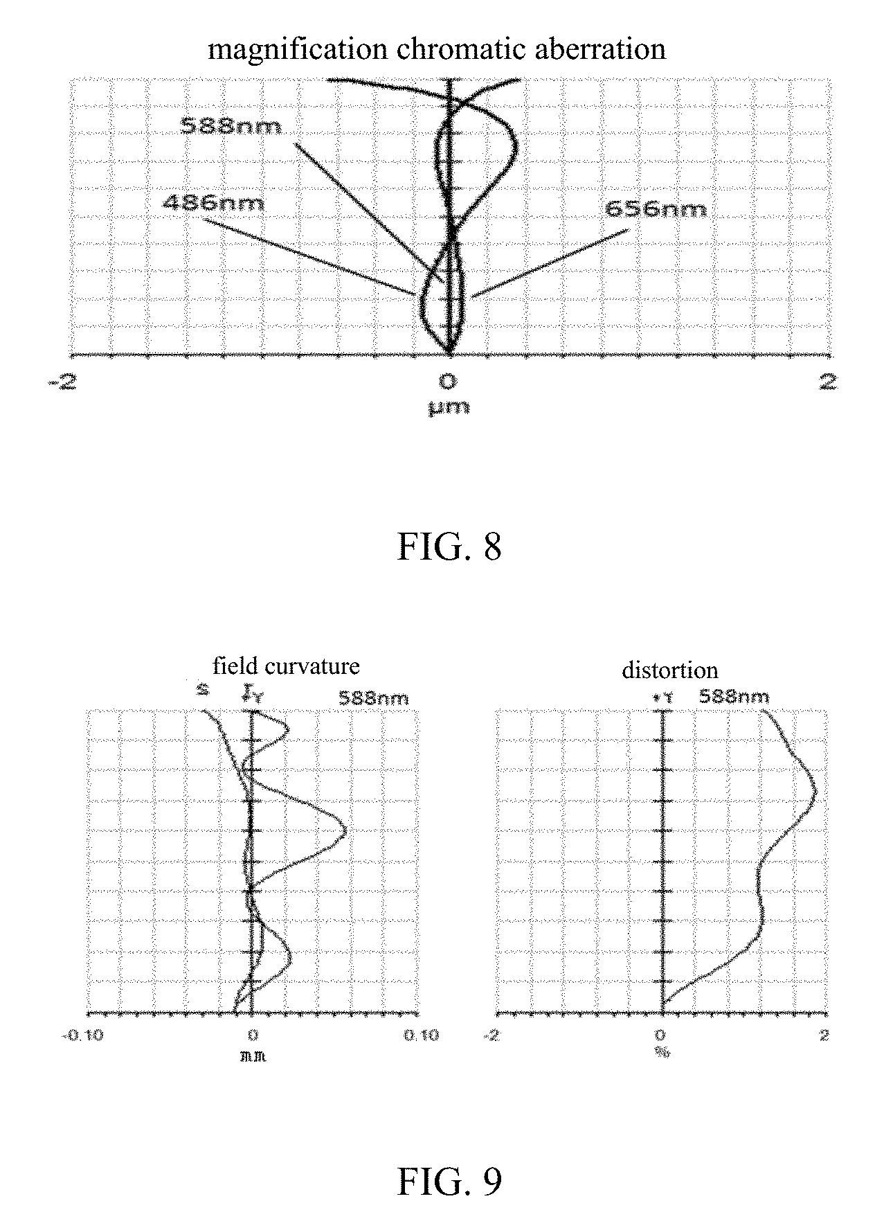
[0017] FIG. 8 is a diagram of a magnification chromatic aberration of the camera lens LA of Embodiment 2.
[0018] FIG. 9 is a diagram of field curvature and distortion of the camera lens LA of Embodiment 2.
DESCRIPTION OF EMBODIMENTS
[0019] An embodiment of a camera lens according to the present disclosure will be described with reference to the drawings. A diagram showing a structure of the camera lens according to the embodiments of the present disclosure is as shown in FIG. 1. The camera lens LA has a four-lens system which includes a first lens L1, a second lens L2, a third lens L3 and a fourth lens L4, which are arranged from an object side toward an image side. A glass plate GF is provided between the fourth lens L4 and an imaging plane. The glass plate GF can be a glass plate using a cover glass or having an IR cut-off filter and other functions. In addition, the glass plate GF may not be provided between the fourth lens L4 and the imaging plane.
[0020] The first lens L1 is a lens having a positive refractive power, the second lens L2 is a lens having a negative refractive power, the third lens L3 is a lens having a positive refractive power, and the fourth lens L4 is a lens having a negative refractive power. With respect to the lens surfaces of these four lenses, it is preferable to make them be aspheric surfaces in order to satisfactorily correct various aberrations.
[0021] The camera lens LA satisfies the following relational expressions (1) to (6):
0.50f1/f0.68 (1)
-1.50f2/f-1.30 (2)
-0.50f1/f2-0.45 (3)
-0.90(R1+R2)/(R1-R2)-0.60 (4)
0.15(R3+R4)/(R3-R4)0.85 (5)
1.10(R7+R8)/(R7-R8)3.00 (6),
in which:
[0022] f denotes an overall focal length of the lens system,
[0023] f1 denotes a focal length of the first lens,
[0024] f2 denotes a focal length of the second lens,
[0025] R1 denotes a curvature radius of an object side surface of the first lens, and
[0026] R2 denotes a curvature radius of an image side surface of the first lens;
[0027] R3 denotes a curvature radius of an object side surface of the second lens, and
[0028] R4 denotes a curvature radius of an image side surface of the second lens;
[0029] R7 denotes a curvature radius of an object side surface of the fourth lens, and
[0030] R8 denotes a curvature radius of an image side surface of the fourth lens.
[0031] The relational expression (1) specifies the positive refractive power of the first lens L1. When it is out of the range of the relational expression (1), it is not preferable because it is difficult to achieve miniaturization with a bright Fno.
[0032] Furthermore, it is further preferable to set the numerical range of the relational expression (1) as the numerical range of the following relational expression (1-A):
0.63f1/f0.66 (1-A),
[0033] The relational expression (2) specifies the negative refractive power of the second lens L2. When it is out of the range of the relational expression (2), it is not preferable because it is difficult to achieve miniaturization with a bright Fno.
[0034] Furthermore, it is further preferable to set the numerical range of the relational expression (2) as the numerical range of the following relational expression (2-A):
-1.38f2/f-1.32 (2-A).
[0035] The relational expression (3) specifies the ratio between the focal length of the first lens L1 and the focal length of the second lens L2. When it is out of the range of the relational expression (3), it is not preferable because it is difficult to achieve miniaturization with a bright Fno.
[0036] Furthermore, it is further preferable to set the numerical range of the relational expression (3) as the numerical range of the following relational expression (3-A):
-0.49f1/f2-0.46 (3-A).
[0037] The relational expression (4) specifies the shape of the first lens L1. When it is out of the range of the relational expression (4), it is not preferable because it is difficult to achieve miniaturization with a bright Fno.
[0038] Furthermore, it is further preferable to set the numerical range of the relational expression (4) as the numerical range of the following relational expression (4-A):
-0.86(R1+R2)/(R1-R2)-0.62 (4-A).
[0039] The relational expression (5) specifies the shape of the second lens L2. When it is out of the range of the relational expression (5), it is not preferable because it is difficult to achieve miniaturization with a bright Fno.
[0040] Furthermore, it is further preferable to set the numerical range of the relational expression (5) as the numerical range of the following relational expression (5-A):
0.16(R3+R4)/(R3-R4)0.80 (5-A).
[0041] The relational expression (6) specifies the shape of the fourth lens L4. When it is out of the range of the relational expression (6), it is not preferable because it is difficult to achieve miniaturization with a bright Fno.
[0042] Furthermore, it is further preferable to set the numerical range of the relational expression (6) as the numerical range of the following relational expression (6-A):
1.15(R7+R8)/(R7-R8)2.80 (6-A).
[0043] The third lens L3 is a lens having a positive refractive power, and satisfies the following relational expressions (7) and (8):
0.65f3/f1.80 (7)
2.40(R5+R6)/(R5-R6)5.00 (8)
[0044] wherein
[0045] f denotes the overall focal length of the lens system,
[0046] f3 denotes the focal length of the third lens,
[0047] R5 denotes the curvature radius of the object side surface of the third lens, and
[0048] R6 denotes the curvature radius of the image side surface of the third lens.
[0049] The relational expression (7) specifies the positive refractive power of the third lens L3. When it is out of the range of the relational expression (7), it is not preferable because it is difficult to achieve miniaturization with a bright Fno.
[0050] Furthermore, it is further preferable to set the numerical range of the relational expression (7) as the numerical range of the following relational expression (7-A):
0.70f3/f1.62 (7-A).
[0051] The relational expression (8) specifies the shape of the third lens L3. When it is out of the range of the relational expression (8), it is not preferable because it is difficult to achieve miniaturization with a bright Fno.
[0052] Furthermore, it is further preferable to set the numerical range of the relational expression (8) as the numerical range of the following relational expression (8-A):
2.50(R5+R6)/(R5-R6)4.80 (8-A).
[0053] The fourth lens L4 is a lens having a negative refractive power, and satisfies the following relational expression (9):
-1.20f4/f-0.50 (9),
[0054] wherein
[0055] f denotes the overall focal length of the lens system, and
[0056] f4 denotes the focal length of the fourth lens.
[0057] The relational expression (9) specifies the positive refractive power of the fourth lens L4. When it is out of the range of the relational expression (9), it is not preferable because it is difficult to achieve miniaturization with a bright Fno.
[0058] Furthermore, it is further preferable to set the numerical range of the relational expression (9) as the numerical range of the following relational expression (9-A):
-1.15f4/f-0.60 (9-A).
[0059] Each of the four lenses constituting the camera lens LA satisfies the structure and relational expression described above, and it is possible to obtain a camera lens which has good optical properties, a small size and a bright Fno.
Embodiments
[0060] In the following, the camera lens LA according to the present disclosure will be explained by using the embodiments. The symbols as used in the embodiments are listed as follows. In addition, the unit for the distance, the radium and the center thickness is mm.
[0061] f: the overall focal length of the camera lens LA;
[0062] f1: the focal length of the first lens L1;
[0063] f2: the focal length of the second lens L2;
[0064] f3: the focal length of the third lens L3;
[0065] f4: the focal length of the fourth lens L4;
[0066] Fno: F-number;
[0067] 2.omega.: full image angle;
[0068] S1: open aperture;
[0069] R: the curvature radius of the optical surface, which is the center curvature radius of the lens;
[0070] R1: the curvature radius of the object side surface of the first lens L1;
[0071] R2: the curvature radius of the image side surface of the first lens L1;
[0072] R3: the curvature radius of the object side surface of the second lens L2;
[0073] R4: the curvature radius of the image side surface of the second lens L2;
[0074] R5: the curvature radius of the object side surface of the third lens L3;
[0075] R6: the curvature radius of the image side surface of the third lens L3;
[0076] R7: the curvature radius of the object side surface of the fourth lens L4;
[0077] R8: the curvature radius of the image side surface of the fourth lens L4;
[0078] R9: the curvature radius of the object side surface of the glass plate GF;
[0079] R10: the curvature radius of the image side surface of the glass plate GF;
[0080] d: the center thickness of the lens or the distance between the lenses;
[0081] d0: the axial distance from the open aperture S1 to the object side surface of the first lens L1;
[0082] d1: the center thickness of the first lens L1;
[0083] d2: the axial distance from the image side surface of the first lens L1 to the object side surface of the second lens L2;
[0084] d3: the center thickness of the second lens L2;
[0085] d4: the axial distance from the image side surface of the second lens L2 to the object side surface of the third lens L3;
[0086] d5: the center thickness of the third lens L3;
[0087] d6: the axial distance from the image side surface of the third lens L3 to the object side surface of the fourth lens L4;
[0088] d7: the center thickness of the fourth lens L4;
[0089] d8: the axial distance from the image side surface of the fourth lens L4 to the object side surface of the glass plate GF;
[0090] d9: the center thickness of the glass plate GF;
[0091] d10: the axial distance from the image side surface of the glass plate GF to the imaging plane;
[0092] nd: the refractive index of line d;
[0093] n1: the refractive index of line d of the first lens L1;
[0094] n2: the refractive index of line d of the second lens L2;
[0095] n3: the refractive index of line d of the third lens L3;
[0096] n4: the refractive index of line d of the fourth lens L4;
[0097] n5: the refractive index of line d of the glass plate GF;
[0098] d: the Abbe number;
[0099] .nu.1: the Abbe number of the first lens L1;
[0100] .nu.2: the Abbe number of the second lens L2;
[0101] .nu.3: the Abbe number of the third lens L3;
[0102] .nu.4: the Abbe number of the fourth lens L4;
[0103] .nu.5: the Abbe number of the glass plate GF;
[0104] TTL: optical length (the axial distance from the object side surface of the first lens L1 to the imaging plane);
[0105] LB: the axial distance from the image side surface of the fourth lens L4 to the imaging plane (including the thickness of the glass plate GF); and
[0106] IH: image height.
y=(x.sup.2/R)/[1+{1-(k+1)(x.sup.2/R.sup.2)}.sup.1/2]
+A4x.sup.4+A6x.sup.6+A8x.sup.8+A10x.sup.10+A12x.sup.12+A14x.sup.14+A16x.- sup.16 (10)
[0107] R is the axial curvature radius, k is the conic coefficient, and A4, A6, A8, A10, A12, A14, and A16 are aspheric coefficients.
[0108] For the sake of convenience, the aspheric surface represented by the relational expression (10) is used as an aspheric surface of each of the lenses. However, the present disclosure is not limited to the aspheric surface represented by the relational expression (10).
Embodiment 1
[0109] FIG. 2 is a structural diagram of the camera lens LA of Embodiment 1. Each of the first lens L1 to the fourth lens L4 constituting the camera lens LA of Embodiment 1 has a curvature radius of R of the object side and image side, a center thickness of the lens or a distance d between the lenses, a refractive index nd, and an Abbe number .nu. d as shown in Table 1, and a conic coefficient k and an aspheric coefficient as shown in Table 2.
TABLE-US-00001 TABLE 1 R d nd .nu.d S1 .infin. d0 = -0.140 R1 1.08768 d1 = 0.491 n1 1.544 .nu.1 56.0 R2 -4.95472 d2 = 0.048 R3 -9.37200 d3 = 0.250 n2 1.661 .nu.2 20.4 R4 3.16985 d4 = 0.400 R5 -1.70699 d5 = 0.633 n3 1.544 .nu.3 56.0 R6 -0.74546 d6 = 0.093 R7 8.83076 d7 = 0.364 n4 1.535 .nu.4 56.1 R8 0.81025 d8 = 0.300 R9 .infin. d9 = 0.210 n5 1.517 .nu.5 64.2 R10 .infin. d10 = 0.366
TABLE-US-00002 TABLE 2 conic coefficient aspheric coefficient k A4 A6 A8 A10 A12 A14 A16 R1 3.65E-01 -7.89E-02 -2.19E-01 7.16E-01 -6.85E+00 2.22E+01 -4.25E+01 2.93E+01 R2 -1.45E+02 2.95E-02 -1.31E+00 4.65E+00 -1.56E+01 3.07E+01 -3.30E+01 1.56E+01 R3 1.19E+01 4.23E-01 -1.39E+00 4.24E+00 -2.06E+01 9.46E+01 -2.18E+02 1.91E+02 R4 -1.82E+01 7.07E-01 -6.72E+00 7.41E+01 -4.60E+02 1.61E+03 -2.98E+03 2.25E+03 R5 -3.91E+01 -8.96E-01 1.88E+00 -5.24E+00 1.25E+01 -3.09E+01 6.27E+01 -6.87E+01 R6 -2.93E+00 -8.29E-02 -2.19E+00 1.16E+01 -2.98E+01 4.26E+01 -3.12E+01 9.10E+00 R7 -2.20E+03 -6.82E-01 1.02E+00 -8.44E-01 4.95E-01 -1.99E-01 4.59E-02 -4.27E-03 R8 -7.15E+00 -3.75E-01 4.24E-01 -3.48E-01 1.78E-01 -5.61E-02 9.88E-03 -7.17E-04
[0110] Table 5 below shows the numerical values defined in Embodiments 1 and 2 and the numerical values corresponding to the parameters specified by the relational expressions (1) to (9).
[0111] The spherical aberration of the camera lens LA of Embodiment 1 is as shown in FIG. 3, the magnification chromatic aberration of magnification thereof is as shown in FIG. 4, and the field curvature and the distortion are as shown in FIG. 5. Furthermore, the field curvature S in FIG. 5 is the field curvature for the sagittal imaging plane, and T is the field curvature for the meridianal imaging plane, and the same applies to Embodiment 2. As can be seen from FIGS. 3 to 5, the camera lens LA of Embodiment 1 has TTL=3.155 mm, Fno=2.05, and thus has a small size, a bright Fno and good optical properties.
Embodiment 2
[0112] FIG. 6 is a structural diagram of the camera lens LA of Embodiment 2. Each of the first lens L1 to the fourth lens L4 constituting the camera lens LA of Embodiment 2 has a curvature radius of R of the object side and image side, a center thickness of the lens or a distance d between the lenses, a refractive index nd, and an Abbe number .nu. d as shown in Table 3, and a conic coefficient k and an aspheric coefficient as shown in Table 4.
TABLE-US-00003 TABLE 3 R d nd .nu.d S1 .infin. d0 = -0.140 R1 1.09554 d1 = 0.494 n1 1.544 .nu.1 56.0 R2 -5.16349 d2 = 0.049 R3 -11.94777 d3 = 0.250 n2 1.661 .nu.2 20.4 R4 2.99620 d4 = 0.407 R5 -1.68265 d5 = 0.671 n3 1.544 .nu.3 56.0 R6 -0.74005 d6 = 0.091 R7 8.66711 d7 = 0.362 n4 1.535 .nu.4 56.1 R8 0.81006 d8 = 0.400 R9 .infin. d9 = 0.210 n5 1.517 .nu.5 64.2 R10 .infin. d10 = 0.276
TABLE-US-00004 TABLE 4 conic coefficient aspheric coefficient k A4 A6 A8 A10 A12 A14 A16 R1 3.54E-01 -8.53E-02 -2.22E-01 7.19E-01 -6.85E+00 2.22E+01 -4.27E+01 2.94E+01 R2 -1.42E+02 1.06E-02 -1.33E+00 4.65E+00 -1.56E+01 3.08E+01 -3.31E+01 1.50E+01 R3 -4.96E+01 4.21E-01 -1.39E+00 4.23E+00 -2.06E+01 9.46E+01 -2.18E+02 1.91E+02 R4 -1.26E+01 7.31E-01 -6.67E+00 7.41E+01 -4.60E+02 1.61E+03 -2.98E+03 2.25E+03 R5 -3.80E+01 -8.99E-01 1.92E+00 -5.21E+00 1.24E+01 -3.07E+01 6.37E+01 -6.61E+01 R6 -2.89E+00 -8.48E-02 -2.19E+00 1.16E+01 -2.98E+01 4.25E+01 -3.12E+01 9.10E+00 R7 -2.09E+03 -6.82E-01 1.02E+00 -8.44E-01 4.95E-01 -1.99E-01 4.58E-02 -4.22E-03 R8 -7.08E+00 -3.75E-01 4.24E-01 -3.47E-01 1.78E-01 -5.61E-02 9.87E-03 -7.14E-04
[0113] As shown in Table 5, Embodiment 2 satisfies the relational expressions (1) to (6).
[0114] The spherical aberration of the camera lens LA of Embodiment 2 is as shown in FIG. 7, the magnification chromatic aberration of magnification thereof is as shown in FIG. 8, and the field curvature and the distortion are as shown in FIG. 9. As can be seen from FIGS. 7 to 9, the camera lens LA of Embodiment 2 has TTL=3.210 mm and Fno=2.05, and thus has a small size, a bright Fno and good optical properties.
[0115] Table 5 shows the numerical values defined in the embodiments and the numerical values corresponding to the parameters specified by the relational expressions (1) to (9).
[0116] Furthermore, the units of the numerical values shown in Table 5 are respectively 2.omega.(.degree.), f(mm), f1(mm), f2(mm), f3(mm), f4(mm), TTL(mm), LB (mm), and IH (mm).
TABLE-US-00005 TABLE 5 Embodiment 1 Embodiment 2 Notes f1/f 0.650 0.649 Exp(1) f2/f -1.369 -1.366 Exp(2) f1/f2 -0.475 -0.475 Exp(3) (R1 + R2)/(R1 - R2) -0.640 -0.650 Exp(4) (R3 + R4)/(R3 - R4) 0.495 0.599 Exp(5) (R7 + R8)/(R7 - R8) 1.202 1.206 Exp(6) f3/f 0.761 0.737 Exp(7) (R5 + R6)/(R5 - R6) 2.551 2.570 Exp(8) f4/f -0.652 -0.644 Exp(9) Fno 2.05 2.05 2 .omega. 68.8 68.3 f 2.596 2.634 f1 1.688 1.709 f2 -3.553 -3.598 f3 1.975 1.942 f4 -1.694 -1.697 TTL 3.155 3.210 LB 0.876 0.886 IH 1.815 1.815
LIST OF REFERENCE SIGNS
[0117] LA: camera lens
[0118] S1: aperture
[0119] L1: the first lens
[0120] L2: the second lens
[0121] L3: the third lens
[0122] L4: the fourth lens
[0123] GF: glass plate
[0124] R: the curvature radius of the optical surface, which is the center curvature radius of the lens
[0125] R1: the curvature radius of the object side surface of the first lens L1
[0126] R2: a curvature radius of the image side surface of the first lens L1
[0127] R3: a curvature radius of the object side surface of the second lens L2
[0128] R4: a curvature radius of the image side surface of the second lens L2
[0129] R5: a curvature radius of the object side surface of the third lens L3
[0130] R6: a curvature radius of the image side surface of the third lens L3
[0131] R7: a curvature radius of the object side surface of the fourth lens L4
[0132] R8: a curvature radius of the image side surface of the fourth lens L4
[0133] R9: a curvature radius of the object side surface of the glass plate GF
[0134] R10: a curvature radius of the image side surface of the glass plate GF
[0135] d: the center thickness of the lens or the distance between the lenses
[0136] d0: the axial distance from the open aperture S1 to the object side surface of the first lens L1
[0137] d1: the center thickness of the first lens L1
[0138] d2: the axial distance from the image side surface of the first lens L1 to the object side surface of the second lens L2
[0139] d3: the center thickness of the second lens L2
[0140] d4: the axial distance from the image side surface of the second lens L2 to the object side surface of the third lens L3
[0141] d5: the center thickness of the third lens L3
[0142] d6: the axial distance from the image side surface of the third lens L3 to the object side surface of the fourth lens L4
[0143] d7: the center thickness of the fourth lens L4
[0144] d8: the axial distance from the image side surface of the fifth lens L5 to the object side surface of the glass plate GF
[0145] d9: the center thickness of the glass plate GF
[0146] d10: the axial distance from the image side surface of the glass plate GF to the imaging plane
* * * * *
D00000
D00001
D00002
D00003
D00004
D00005
P00001
XML
uspto.report is an independent third-party trademark research tool that is not affiliated, endorsed, or sponsored by the United States Patent and Trademark Office (USPTO) or any other governmental organization. The information provided by uspto.report is based on publicly available data at the time of writing and is intended for informational purposes only.
While we strive to provide accurate and up-to-date information, we do not guarantee the accuracy, completeness, reliability, or suitability of the information displayed on this site. The use of this site is at your own risk. Any reliance you place on such information is therefore strictly at your own risk.
All official trademark data, including owner information, should be verified by visiting the official USPTO website at www.uspto.gov. This site is not intended to replace professional legal advice and should not be used as a substitute for consulting with a legal professional who is knowledgeable about trademark law.