High Temperature Plate Fin Heat Exchanger
Disori; Michael A. ; et al.
U.S. patent application number 15/914042 was filed with the patent office on 2019-09-12 for high temperature plate fin heat exchanger. The applicant listed for this patent is United Technologies Corporation. Invention is credited to Alexander Broulidakis, Adam J. Diener, Michael A. Disori, David J. Hyland, William P. Stillman, Jeremy Styborski.
| Application Number | 20190277579 15/914042 |
| Document ID | / |
| Family ID | 65724243 |
| Filed Date | 2019-09-12 |

| United States Patent Application | 20190277579 |
| Kind Code | A1 |
| Disori; Michael A. ; et al. | September 12, 2019 |
HIGH TEMPERATURE PLATE FIN HEAT EXCHANGER
Abstract
A heat exchanger includes a plate portion including a top surface, bottom surface, a leading edge, a trailing edge and a plurality of internal passages extending between an inlet and an outlet. A fin portion extends outward from one of the top surface and the bottom surface. The fin portion and the leading edge of the plate portion define a leading edge contour. A cast plate for a heat exchanger and a method are also disclosed.
| Inventors: | Disori; Michael A.; (Glastonbury, CT) ; Stillman; William P.; (Sturbridge, MA) ; Diener; Adam J.; (Marlborough, CT) ; Broulidakis; Alexander; (Tolland, CT) ; Hyland; David J.; (Portland, CT) ; Styborski; Jeremy; (Manchester, CT) | ||||||||||
| Applicant: |
|
||||||||||
|---|---|---|---|---|---|---|---|---|---|---|---|
| Family ID: | 65724243 | ||||||||||
| Appl. No.: | 15/914042 | ||||||||||
| Filed: | March 7, 2018 |
| Current U.S. Class: | 1/1 |
| Current CPC Class: | F28D 1/05383 20130101; F28F 3/025 20130101; F28F 1/26 20130101; F28F 1/022 20130101; F28F 2210/10 20130101; F28F 2215/06 20130101 |
| International Class: | F28F 3/02 20060101 F28F003/02 |
Claims
1. A heat exchanger comprising: a plate portion including a top surface, bottom surface, a leading edge forming a continuous curvilinear surface between the top surface and the bottom surface, a trailing edge and a plurality of internal passages extending between an inlet and an outlet, the continuous curvilinear surface extending along a width of the plate portion transverse to the plurality of internal passages; a fin portion extending outward from one of the top surface and the bottom surface, wherein the fin portion includes a leading edge that merges into the continuous curvilinear surface formed by the leading edge of the plate portion to define a continuous curvilinear leading edge contour.
2. The heat exchanger as recited in claim 1, wherein the fin portion and trailing edge of the plate portion define a trailing edge contour.
3. The heat exchanger as recited in claim 2, wherein the leading edge contour and the trailing edge contour are disposed within a plane transverse to the plurality of internal passages.
4. The heat exchanger as recited in claim 1, wherein the plurality of internal passages comprise one of an elliptical shape and a rectilinear shape in cross-section.
5. The heat exchanger as recited in claim 1, wherein the fin portion includes a fin thickness in cross-section that varies between the leading edge and the trailing edge.
6. The heat exchanger as recited in claim 5, wherein the fin thickness is largest at the leading edge.
7. The heat exchanger as recited in claim 1, wherein the fin portion comprises a plurality of bottom fin portions extending outward from the bottom surface and a plurality of top fin portions extending outward from the top surface, wherein each of the plurality of top fin portions are offset from the plurality of bottom fin portions.
8. The heat exchanger as recited in claim 1, including an inlet manifold in fluid communication with the inlet and an outlet manifold in fluid communication with the outlet.
9. The heat exchanger as recited in claim 1, wherein the plate portion and the fin portion comprise a single unitary cast item.
10. A cast plate for a heat exchanger comprising: a plate portion including a top surface, bottom surface, a curvilinear leading edge, a trailing edge and a plurality of internal passages extending between an inlet and an outlet; and a plurality of bottom fin portions extending outward from the bottom surface and a plurality of top fin portions extending outward from the top surface, wherein each of the plurality of top fin portions are offset from the plurality of bottom fin portions, wherein at least one of the plurality of top fin portions and the bottom fin portions merge with the curvilinear leading edge to define a continuous curvilinear leading edge contour of the plate portion.
11. The cast plate as recited in claim 10, wherein at least one of the plurality of top fin portions and the bottom fin portions define a continuous curvilinear trailing edge contour common with the trailing edge of the plate portion.
12. The cast plate as recited in claim 11, wherein the leading edge contour and the trailing edge contour are disposed within respective planes transverse to the plurality of internal passages.
13. The heat exchanger as recited in claim 12, wherein the plurality of internal passages comprise one of an elliptical shape and a rectilinear shape in cross-section.
14. The heat exchanger as recited in claim 10, wherein each of the plurality of top fin portions and bottom fin portions includes a fin thickness that is largest at the leading edge.
15-18. (canceled)
Description
BACKGROUND
[0001] A plate fin heat exchanger includes adjacent flow paths that transfer heat from a hot flow to a cooling flow. The flow paths are defined by a combination of plates and fins that are arranged to transfer heat from one flow to another flow. The plates and fins are created from sheet metal material brazed together to define the different flow paths. Thermal gradients present in the sheet material create stresses that can be very high in certain locations. The stresses are typically largest in one corner where the hot side flow first meets the coldest portion of the cooling flow. In an opposite corner where the coldest hot side flow meets the hottest cold side flow the temperature difference is much less resulting in unbalanced stresses across the heat exchanger structure. Increasing temperatures and pressures can result in stresses on the structure that can exceed material and assembly capabilities.
[0002] Turbine engine manufactures utilize heat exchangers throughout the engine to cool and condition airflow for cooling and other operational needs. Improvements to turbine engines have enabled increases in operational temperatures and pressures. The increases in temperatures and pressures improve engine efficiency but also increase demands on all engine components including heat exchangers.
[0003] Turbine engine manufacturers continue to seek further improvements to engine performance including improvements to thermal, transfer and propulsive efficiencies.
SUMMARY
[0004] In a featured embodiment, a heat exchanger includes a plate portion including a top surface, bottom surface, a leading edge, a trailing edge and a plurality of internal passages extending between an inlet and an outlet. A fin portion extends outward from one of the top surface and the bottom surface. The fin portion and the leading edge of the plate portion define a leading edge contour.
[0005] In another embodiment according to the previous embodiment, the fin portion and trailing edge of the plate portion define a trailing edge contour.
[0006] In another embodiment according to any of the previous embodiments, the leading edge contour and the trailing edge contour are disposed within a plane transverse to the plurality of internal passages.
[0007] In another embodiment according to any of the previous embodiments, the plurality of internal passages include one of an elliptical shape and a rectilinear shape in cross-section.
[0008] In another embodiment according to any of the previous embodiments, the fin portion includes a fin thickness in cross-section that varies between the leading edge and the trailing edge.
[0009] In another embodiment according to any of the previous embodiments, the fin thickness is largest at the leading edge.
[0010] In another embodiment according to any of the previous embodiments, the fin portion includes a plurality of bottom fin portions extending outward from the bottom surface and a plurality of top fin portions extending outward from the top surface. Each of the plurality of top fin portions are offset from the plurality of top fin portions.
[0011] In another embodiment according to any of the previous embodiments, an inlet manifold is in fluid communication with the inlet and an outlet manifold is in fluid communication with the outlet.
[0012] In another embodiment according to any of the previous embodiments, the plate portion and the fin portion include a single unitary cast item.
[0013] In another featured embodiment, a cast plate for a heat exchanger includes a plate portion including a top surface, bottom surface, a leading edge, a trailing edge and a plurality of internal passages extending between an inlet and an outlet. A plurality of bottom fin portions extend outward from the bottom surface and a plurality of top fin portions extend outward from the top surface. Each of the plurality of top fin portions are offset from the plurality of top fin portions. At least one of the plurality of top fin portions and the bottom fin portions define a leading edge contour common with the leading edge of the plate portion.
[0014] In another embodiment according to the previous embodiment, at least one of the plurality of top fin portions and the bottom fin portions define a trailing edge contour common with the trailing edge of the plate portion.
[0015] In another embodiment according to any of the previous embodiments, the leading edge contour and the trailing edge contour are disposed within respective planes transverse to the plurality of internal passages.
[0016] In another embodiment according to any of the previous embodiments, the plurality of internal passages include one of an elliptical shape and a rectilinear shape in cross-section.
[0017] In another embodiment according to any of the previous embodiments, each of the plurality of top fin portions and bottom fin portions includes a fin thickness that is largest at the leading edge.
[0018] In another featured embodiment, a method of building a heat exchanger includes forming a core defining a plurality of internal passages through a plate portion. The core is inserted within a mold cavity that defines outer surfaces of the plate portion to include a top surface, bottom surface, a leading edge, a trailing edge and plurality of fin portions extending outward from one of the top surface and the bottom surface. The plurality of fin portions and the leading edge of the plate portion are defined to form a leading edge contour. Cast material is introduced into the mold to form a single unitary heat exchanger plate without a joint between the plate portion and the plurality of fin portions. The heat exchanger plate is removed from the mold and removes the core from the plate portion.
[0019] In another embodiment according to the previous embodiment, the plurality of fin portions and the trailing edge of the plate are defined to form a trailing edge contour.
[0020] In another embodiment according to any of the previous embodiments, the mold cavity includes features for defining fin portions on both the top surface and the bottom surface that are offset relative to each other.
[0021] In another embodiment according to any of the previous embodiments, the plurality of fins are cast to include a fin thickness that is largest at the leading edge.
[0022] Although the different examples have the specific components shown in the illustrations, embodiments of this disclosure are not limited to those particular combinations. It is possible to use some of the components or features from one of the examples in combination with features or components from another one of the examples.
[0023] These and other features disclosed herein can be best understood from the following specification and drawings, the following of which is a brief description.
BRIEF DESCRIPTION OF THE DRAWINGS
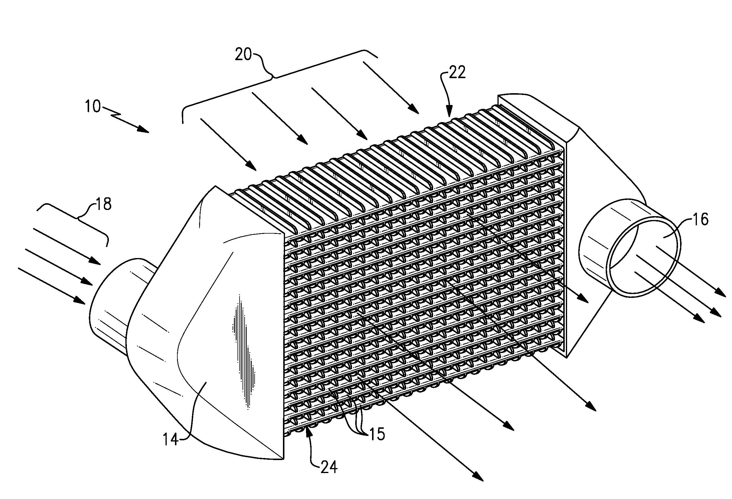
[0024] FIG. 1 is a perspective view of an example heat exchanger.
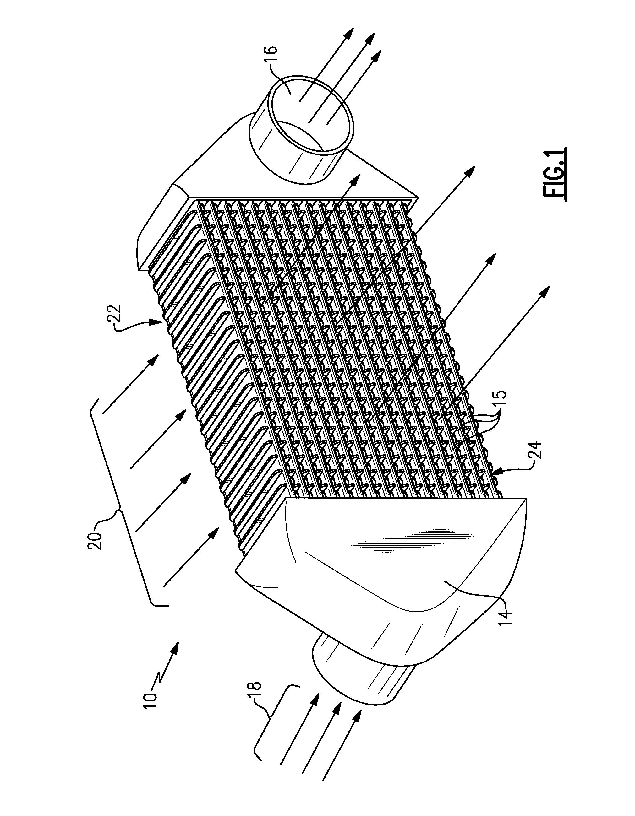
[0025] FIG. 2 is a perspective view of an example plate according to an example embodiment.
[0026] FIG. 3 is an enlarged view of the leading edge of the example plate embodiment.
[0027] FIG. 4 is a cross-sectional view of a portion of the example plate embodiment.
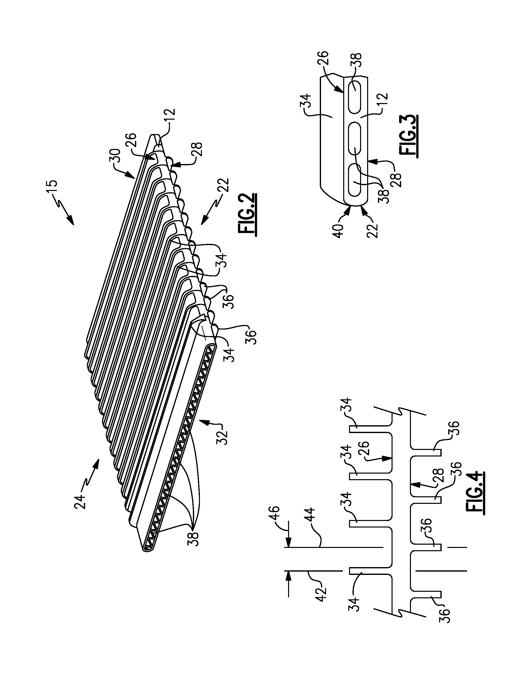
[0028] FIG. 5 is a sectional view of a trailing edge of the example plate embodiment.
[0029] FIG. 6 is another example view of a leading edge of the example plate embodiment.
[0030] FIG. 7 is a partial sectional view of a trailing edge of the example plate embodiment.
[0031] FIG. 8 is an enlarged view of a portion of another example plate embodiment.
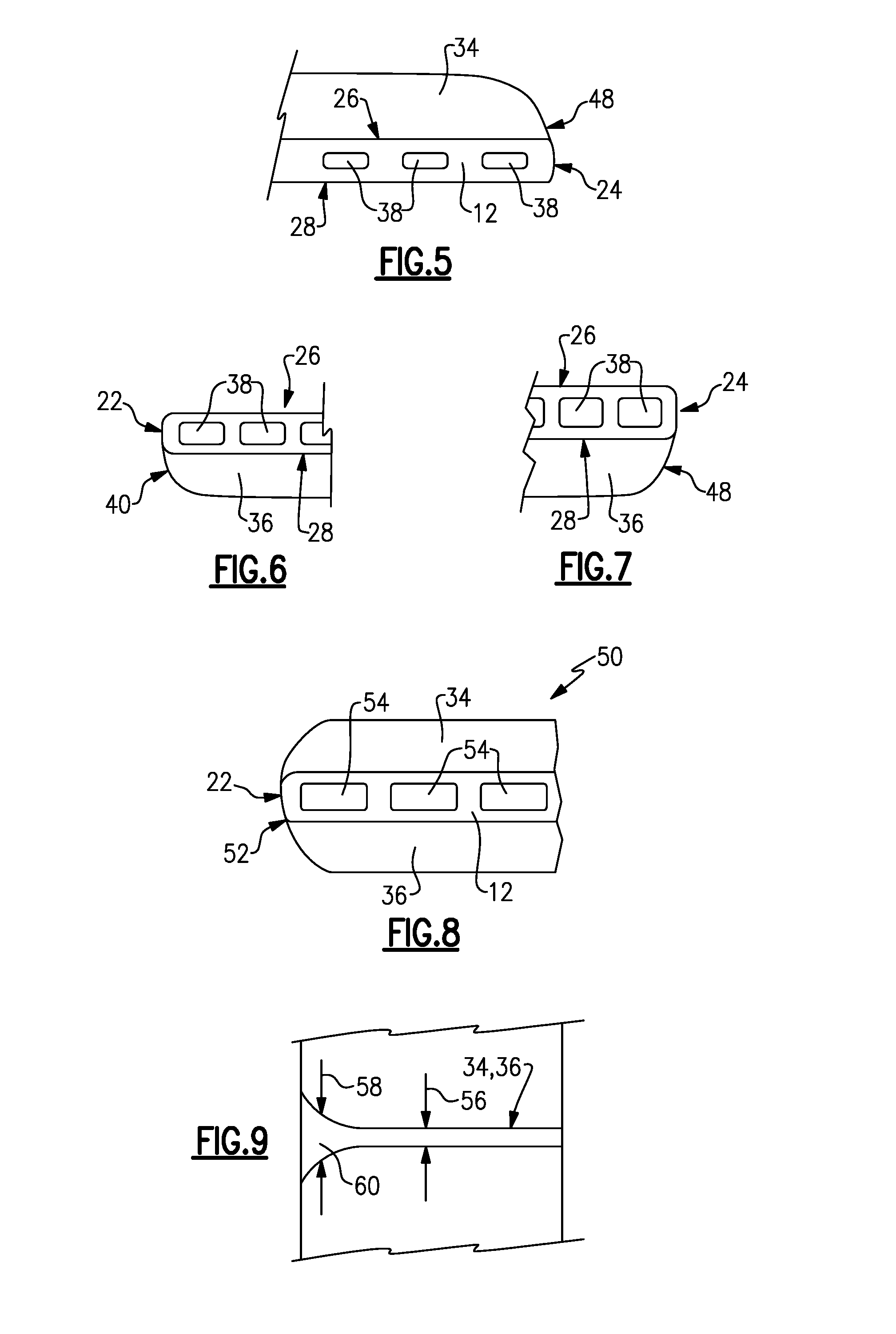
[0032] FIG. 9 is a top view of a fin for the example plate embodiments.
[0033] FIG. 10 is a schematic representation of a method of fabricating an example plate.
DETAILED DESCRIPTION
[0034] Referring to FIG. 1, a heat exchanger 10 is shown and includes a plurality of plates 15 stacked between an inlet manifold 14 and an outlet manifold 16. The plurality of plates 15 define passages for a hot flow schematically shown at 18 that flows through the plates 15 and is cooled by an external cooling flow 20 that flows along an outer surface of each of the plurality of plates 15. Each of the plates 15 includes a leading edge 22 that first encounters the initial incoming cooling airflow 20 and a trailing edge 24 where the cooling airflow 24 is exhausted. It should be understood that although a plurality of plates 15 are shown, it is within the contemplation of this disclosure that any number of plates 15 including a single plate 15 could be utilized for the heat exchanger 10.
[0035] Referring to FIG. 2 with continued reference to FIG. 1, each of the example plate 15 is an integrally formed structure that includes a plate portion 12 and a plurality of upper fins 34 extending from a top surface 26 of the plate portion 12. The plate portion 12 includes a bottom surface 28 from which a plurality of bottom fins 36 extend. The plate portion 12 defines a plurality of internal passages 38 that extends from an inlet 30 to an outlet 32. The passages 38 are for a fluid flow that is cooled and are provided transverse to the plurality of upper fins 34 and bottom fins 36. The fins 34, 36 are integral portions of the plate 15 and extend from the top surface 26 and bottom surface 28. Each of the fins 34, 36 extend longitudinally from the leading edge 22 to the trailing edge 24.
[0036] Referring to FIG. 3 with continued reference to FIG. 2, each of the fins 34, 36 extends to the leading edge 22 and defines a portion of a leading edge contour 40 that corresponds with the leading edge 22 of the plate portion 12. In the embodiment illustrated in FIG. 3, the top fin 34 extends along the top surface 26 between the leading edge 22 and the trailing edge 24. At the leading edge 22 of the plate portion 12, the fin 34 forms the leading edge contour 40 that includes the leading edge 22 of the plate portion 12 along with the leading edge of the top fin 34. The contoured leading edge 40 is an integrated shape that improves aerodynamic performance and fluid flow to improve heat transfer efficiency. Additionally, because the fins 34 extend all the way to the leading edge 22 of the plate portion 12, the leading edge 22 has increased ability to survive debris impact.
[0037] Referring to FIG. 4 with continued reference to FIGS. 2 and 3, the plate 15 is shown in a cross-sectional side view showing that the top fins 34 are disposed within a first plane 42 and the bottom fins 36 are disposed in a separate second plane 44 that is spaced a distance 46 from the first plane 42 of the top fins 34. Accordingly, the top fins 34 are offset relative to the bottom fins 36 to enable stacking of the plates 15 to scale the heat exchanger 10 to application specific requirements.
[0038] Referring to FIG. 5 with continued reference to FIGS. 2 and 3, a trailing edge contour 48 is shown at a trailing edge 24 of the plate portion 12. The trailing edge contour 48 includes the trailing edge 24 of the plate portion 12 that is disposed along the common contour surface 48 with the upper fin 34 at the trailing edge 24.
[0039] Referring to FIGS. 6 and 7, the leading edge contour 40 and trailing edge contour 48 are also applicable to the bottom fins 36 that are interspersed and spaced along the bottom surface of the plate portion 12.
[0040] Referring to FIG. 8, another plate embodiment is schematically shown at 50 and includes an upper fin 34 and lower fin 36 that merge to provide a common contour 52 at the leading edge 22. In this example embodiment, the upper fin 34 and the lower fin 36 are disposed in a common plane such that they both form a portion of the common leading edge contour 52 with a leading edge portion of the plate portion 12. In this example embodiment, the upper fin 34 extends to the leading edge 22 just as the lower fin 36 does and both form a portion of the continuous contour 52 that extends from the top fin 34 to the top of the bottom fin 36.
[0041] In the previous figures, the passages 38 are disclosed by way of example as elongated elliptical shapes. In the example disclosed in FIG. 8, the passages 54 are shown as rectangular shaped. The shape of the passages 38, 54 could be different than those shown and described within the contemplation of this disclosure. Non-circular shaped passages can generate high stress locations, particularly in those areas that are exposed to the highest thermal differences between the incoming hot flow and the cooling air flow. The leading edge counter 40 and the trailing edge contour 48 provide increased thicknesses within the highest stress regions of the plate 15. The increased thickness reduce the stresses encountered as well as preventing potential deflections. Moreover, the integral structure of the plate portions 12 and fin portions 34, 36 enable a shifting and spreading of stresses into the fins 34, 36. The spreading of stresses over additional area and features of each plate 15 improves durability and capabilities to operation at higher temperatures and pressures.
[0042] Referring to FIG. 9, one of the fins 34 and 36 is shown schematically from a top down perspective to illustrate a fin thickness 56 in a direction parallel to the internal passages 38. The thickness 56 varies along the length of each of the fins 34, 36 and is at its greatest portion at a fillet 60 near a leading edge 22 of the plate portion 12. The increased thickness 58 at the leading edge 22 of the plate portion 12 provides increased survivability of the heat exchanger to survive potential debris impact. The increased thickness 58 at the fillet 60 also provides increased protection against cracks and other stresses generated due to thermal gradients encountered during operation.
[0043] Referring to FIG. 10, an example method of fabricating a plate 15 is schematically illustrated and shown at 62 and includes the initial step of forming a core 64. The core 64 is formed to include structures 70 to define the internal passages of a completed cast plate 15. The core 64 is formed from a material that is compatible with the cast material 68 and that can be removed. The core 64 is inserted into a mold 66 that includes cavity surfaces 72 that define the outer surfaces of a completed plate 15. The mold 66 may include several cavities to hold several cores 64 as is understood by those skilled in molding arts. The molten cast material 68 utilized to fabricate the plate 15 is schematically shown and introduced into the mold 66 to form the completed plate 15. Once the material 68 has fully cured, the plate 15 is removed from the mold 66 and the core 64 removed by known removal process. It should be understood that although a method of fabricating the example cast plate 15 is described by way of example, other molding and casting methods and processes could be utilized and are within the contemplation of this disclosure.
[0044] The resulting plate 15 is an integral single unitary part that includes the plate portion 12 that defines the internal passages 38 and a plurality of integrally formed cooling fins 34, 36 extending from the top and bottom surfaces 26, 28. Moreover, each of the fins 34, 36 includes features that provide increased survivability at the leading and trailing edges 22, 24 of the plate 15 to improve impact survivability and also to accommodate thermal stresses caused by thermal gradients encountered during operation.
[0045] Although an example embodiment has been disclosed, a worker of ordinary skill in this art would recognize that certain modifications would come within the scope of this disclosure. For that reason, the following claims should be studied to determine the scope and content of this disclosure.
* * * * *
D00000
D00001
D00002
D00003
D00004
XML
uspto.report is an independent third-party trademark research tool that is not affiliated, endorsed, or sponsored by the United States Patent and Trademark Office (USPTO) or any other governmental organization. The information provided by uspto.report is based on publicly available data at the time of writing and is intended for informational purposes only.
While we strive to provide accurate and up-to-date information, we do not guarantee the accuracy, completeness, reliability, or suitability of the information displayed on this site. The use of this site is at your own risk. Any reliance you place on such information is therefore strictly at your own risk.
All official trademark data, including owner information, should be verified by visiting the official USPTO website at www.uspto.gov. This site is not intended to replace professional legal advice and should not be used as a substitute for consulting with a legal professional who is knowledgeable about trademark law.