Pump reservoir, rectification system and process for low-temperature rectification
Baus; Michael ; et al.
U.S. patent application number 16/345038 was filed with the patent office on 2019-09-12 for pump reservoir, rectification system and process for low-temperature rectification. This patent application is currently assigned to Linde AG. The applicant listed for this patent is LINDE AKTIENGESELLSCHAFT. Invention is credited to Michael Baus, Felix Flegiel, Daniela Lauchner, Christian Matten.
| Application Number | 20190277564 16/345038 |
| Document ID | / |
| Family ID | 57218663 |
| Filed Date | 2019-09-12 |
| United States Patent Application | 20190277564 |
| Kind Code | A1 |
| Baus; Michael ; et al. | September 12, 2019 |
Pump reservoir, rectification system and process for low-temperature rectification
Abstract
The invention provides a cryogenic pump reservoir (100), for a cryogenic liquid to be fed to a pump (208), with an interior reservoir space (103) extending between a reservoir bottom (101) and a reservoir top (102) and comprising a liquid feeding region (104), which is positioned at a first distance from the reservoir bottom (101) in the direction of the reservoir top (102), and a liquid removing region (105), which is positioned at a second distance from the reservoir bottom (101) in the direction of the reservoir top (102), the second distance being greater than the first distance. It is provided that in the liquid feeding region (104) there is formed a liquid feeding opening (106), that the interior reservoir space (103) is at least partially divided in the liquid feeding region (104) by means of a dividing wall (106), which is arranged in such a way that one of its surfaces (107) is aligned in the direction of the liquid feeding opening (106. A corresponding rectification system (200) and a process for low-temperature rectification are likewise the subject of the present invention.
| Inventors: | Baus; Michael; (Grafelfing, DE) ; Flegiel; Felix; (Munich, DE) ; Lauchner; Daniela; (Meitingen, DE) ; Matten; Christian; (Pullach, DE) | ||||||||||
| Applicant: |
|
||||||||||
|---|---|---|---|---|---|---|---|---|---|---|---|
| Assignee: | Linde AG Munich DE |
||||||||||
| Family ID: | 57218663 | ||||||||||
| Appl. No.: | 16/345038 | ||||||||||
| Filed: | October 25, 2017 | ||||||||||
| PCT Filed: | October 25, 2017 | ||||||||||
| PCT NO: | PCT/EP2017/077304 | ||||||||||
| 371 Date: | April 25, 2019 |
| Current U.S. Class: | 1/1 |
| Current CPC Class: | C10G 5/06 20130101; B01D 3/141 20130101; C10G 2300/1025 20130101; C10L 3/101 20130101; C10L 2290/543 20130101; F04B 23/02 20130101; F25J 3/0295 20130101; B01D 3/20 20130101; F25J 2200/02 20130101; F25J 3/0209 20130101; C10L 2290/54 20130101; F25J 2210/12 20130101; F25J 2235/80 20130101; F25J 2290/62 20130101; F25J 2235/60 20130101; F25J 3/0238 20130101; F25J 2280/02 20130101; F25J 2200/72 20130101; C10G 31/06 20130101; F25J 3/0219 20130101; F25J 3/0233 20130101 |
| International Class: | F25J 3/02 20060101 F25J003/02; F04B 23/02 20060101 F04B023/02; C10G 5/06 20060101 C10G005/06; C10L 3/10 20060101 C10L003/10; C10G 31/06 20060101 C10G031/06 |
Foreign Application Data
| Date | Code | Application Number |
|---|---|---|
| Oct 25, 2016 | EP | 16020414.5 |
Claims
1. A cryogenic pump reservoir (100), for a cryogenic liquid to be fed to a pump (208), the pump reservoir (100) comprising an interior reservoir space (103) extending between a reservoir bottom (101) and a reservoir top (102); a liquid feeding region (104), which is positioned at a first distance from the reservoir bottom (101) in the direction of the reservoir top (102); and a liquid removing region (105), which is positioned at a second distance from the reservoir bottom (101) in the direction of the reservoir top (102), the second distance being greater than the first distance, characterized in that in the liquid feeding region (104) there is provided a liquid feeding opening (106), and the interior reservoir space (103) is at least partially divided in the liquid feeding region (104) by a dividing wall (107) having at least one surface, wherein the dividing wall is arranged such that the at least one of its surfaces (108) is aligned in the direction of the liquid feeding opening (106).
2. The cryogenic pump reservoir (100) according to claim 1, in which the reservoir bottom (101) is tapered in a direction away from the interior reservoir space (103), and has a solids outlet (109).
3. The cryogenic pump reservoir (100) according to claim 1 or 2, in which a liquid feeding line is attached to the liquid feeding opening (106) and the liquid feeding line has a line axis in its end region, wherein the dividing wall (107) is arranged in such a way that its surface (108) that is aligned in the direction of the liquid feeding opening (106) and is arranged at an angle of 80 to 100.degree. to the line axis.
4. The cryogenic pump reservoir (100) according to one of the preceding claims, in which the interior reservoir space (103) has in the liquid feeding region (104) a cross section that is divided into two parts by the dividing wall (107), whereby the area of the two parts differs by no more than 20%.
5. The cryogenic pump reservoir (100) according to one of the preceding claims, in which the interior reservoir space (103) between the liquid feeding region (104) and the liquid removing region (105) comprises a gas collecting region (110) that has gas collecting trays (111), and wherein the gas collecting trays (111) comprise gas collecting structures (112) aligned in the direction of the reservoir bottom (101), and wherein attached to one or each of the gas collecting trays (111) are provided gas lines (113) that extend towards of the reservoir top (102).
6. The cryogenic pump reservoir (100) according to claim 5, in which the gas collecting structures (112) are formed as well structures having an opening in the direction of the reservoir bottom (101).
7. The cryogenic pump reservoir (100) according to claim 5, in which the gas collecting structures (112) take the form of a number of grooves in the gas collecting trays (111).
8. The cryogenic pump reservoir (100) according to one of claims 5 to 7, in which at least two gas collecting trays (111) are provided in the gas collecting region (110), and each gas collecting tray (111) partially covers a cross section of the interior reservoir space (103), and the at least two gas collecting trays are arranged offset in relation to one another.
9. The cryogenic pump reservoir (100) according to one of the preceding claims, in which a liquid removing opening (114) is provided in the liquid removing region (105), the liquid removing opening (114) having a vortex breaker (115) which is led out from the interior reservoir space (103).
10. Rectification system (200) comprising: a rectification column (201) having a column top (202), a cooling device (203) and a condensate separator (206) having a liquid removing opening (207), wherein the column top (202) is connected by means of a first line (203) to the cooling device (204); and the cooling device (204) is connected by means of a second line (205) to the condensate separator (206); the system further comprising a cryogenic pump reservoir (100) according to one of the preceding claims, wherein the liquid feeding opening (106) of the pump reservoir (100) is fluidically coupled to the liquid removing opening (207).
11. Rectification system (200) according to claim 10, also comprising a pump (208), which is configured to return the cryogenic liquid from the liquid removing region (105) of the pump reservoir (100) to the column top (202) of the rectification column (201).
12. Rectification system (200) according to claim 10 or 11, in which the pump reservoir (100) has a gas outlet (116), which is connected to a gas inlet (209) of the condensate separator (206).
13. Process for low-temperature rectification, wherein the method comprises using a pump reservoir (100) according to one of claims 1 to 9 or using a rectification system (200) according to one of claims 10 to 12.
14. Process according to claim 13, comprising providing a supply of the cryogenic liquid having a temperature of -90 to -110.degree. C.; and operating the pump reservoir (100) at a pressure level of 19 to 25 bar (abs.).
Description
BACKGROUND TO THE INVENTION
[0001] The invention relates to a pump reservoir, to a rectification system with a pump reservoir and to a process for low-temperature rectification according to the preambles of the independent patent claims.
[0002] Low-temperature rectification processes are used in a series of different technical areas. One example of this is the processing of mixtures of substances from steam cracking processes, as known in principle from the prior art and explained for example in the article "Ethylene" in Ullmann's Encyclopedia of Industrial Chemistry.
[0003] If corresponding mixtures of substances contain methane, and possibly components that boil at a temperature lower than methane, such as hydrogen and carbon monoxide, processing them for the purposes of separation may involve the use of so-called demethanizers, in which the methane and, possibly, the lighter components of components that boil at a temperature higher than methane, in particular of heavier hydrocarbons, are separated. A corresponding input mixture may already be obtained for its part from a processing operation, for example in a so-called deethanizer. In this specific case, the input mixture only contains as heavier hydrocarbons hydrocarbons with two carbon atoms.
[0004] In a demethanizer, a low-temperature rectification column is used, a column that is designed and operated in such a way that at its top there forms a top gas which predominantly or exclusively contains the methane and possibly the components that boil more readily than methane. In the bottom of the low temperature rectification column, on the other hand, there is deposited a bottom liquid which predominantly or exclusively contains the components that boil at a higher temperature than methane.
[0005] To be able to operate such a low-temperature rectification column, it is typically necessary to give off a liquid, methane-rich reflux in its top region. This is usually formed by at least a fraction of the top gas of the low-temperature rectification column being liquefied in a top condenser and pumped back to the low-temperature rectification column by means of a pump.
[0006] For separating the liquefied fraction of the top gas, a condensate separator is used, from which the pump for pumping back the liquefied fraction of the top gas is fed. While doing so, it is important to avoid feeding to the pump any appreciable amount of gas that could otherwise damage it. It is likewise disadvantageous if solid components are fed to the pump, for example residual carbon dioxide, which is contained in a corresponding top gas and may be deposited from the latter as solid matter during the liquefaction. The pump is therefore typically not fed directly from the separating tank, but by way of an interposed pump reservoir, which is also referred to as a "pump chamber".
[0007] Even though reference has been made above to a steam cracking process and to the processing of a gas mixture thereby produced, the present invention is suitable in the same way for other processes, in particular those in which the demethanizers mentioned are used, for example also for processing natural gas. The invention can always be used and be appropriate whenever a corresponding low-temperature rectification is performed and/or cryogenic liquids are transported by means of pumps.
[0008] The present invention addresses the problem of being able to feed a correspondingly cryogenic liquid to a pump preferably without gaseous components and solids, or with only very small fractions of gaseous components and solids.
SUMMARY OF THE INVENTION
[0009] Against this background, the present invention proposes a cryogenic pump reservoir, a rectification system with a cryogenic pump reservoir and a process for low-temperature rectification with the features of the independent patent claims. Preferred refinements are respectively the subject of the dependent patent claims and of the description that follows.
[0010] The present invention is based on the realization that it is particularly advantageous to use a cryogenic pump reservoir which is intended to temporarily store a cryogenic liquid that is to be fed to a pump and to feed it to the pump in a suitable state. The pump reservoir is provided with a dividing wall in a liquid feeding region. Advantageously, the pump reservoir also has a tapering reservoir bottom, so that solids collecting in the reservoir bottom can be drawn off out of the reservoir bottom by way of a solids outlet that is likewise provided.
[0011] In this respect, the present invention proposes in detail a cryogenic pump reservoir for a cryogenic liquid to be fed to a pump that has an interior reservoir space extending between a reservoir bottom and a reservoir top. The interior reservoir space has a liquid feeding region, which is positioned at a first distance from the reservoir bottom in the direction of the reservoir top, and a liquid removing region, which is positioned at a second distance from the reservoir bottom in the direction of the reservoir top. If such a pump reservoir is used in the way that is conventional in the art, the reservoir bottom is located at the lowest point of a corresponding pump reservoir, the reservoir top at the highest point. Typically, the reservoir space is surrounded by a cylindrical reservoir wall, but other geometrical configurations may also be provided.
[0012] In particular, a geometrical axis, about which the reservoir shell and consequently the interior reservoir space are centered, may extend between the reservoir top and the reservoir bottom. A pump reservoir of the type discussed here may typically be an elongate, column-like apparatus, which however, by contrast with rectification or absorption columns, is not used primarily for separating substances but for storing liquids.
[0013] The first distance, i.e. the distance between the reservoir bottom and the liquid feeding region, is less than the second distance, i.e. the distance between the reservoir bottom and the liquid removing region. In other words, when a corresponding pump reservoir is used in a way that is conventional in the art, the liquid removing region is arranged above the liquid feeding region.
[0014] A liquid feeding region or a liquid removing region is in this case defined on the one hand as a region around a liquid feeding opening or the mouth of a liquid feeding line into the interior reservoir space and on the other hand as a region around a liquid removing opening or the outlet of a liquid removing line from the interior reservoir space. A liquid feeding region is the region that is influenced directly by the liquid feed, for example a region of increased turbulences or flows. A corresponding statement applies analogously to the liquid removing region. Further regions, in particular mere storage regions, but also the gas collecting regions explained below, may be provided between the liquid feeding region and the liquid removing region. Under the liquid feeding region there is the reservoir bottom, above the liquid removing region there is a further region of the interior reservoir space, which depending on the filling level of the pump reservoir is filled for example with liquid or evaporated gas.
[0015] It is thus provided within the scope of the present invention that in the liquid feeding region there is a liquid feeding opening, and that the reservoir space is at least partially divided in the liquid feeding region by means of a dividing wall, which is arranged in such a way that one of its surfaces is aligned in the direction of the liquid feeding opening. Advantageously, the reservoir bottom also tapers in a direction away from the interior reservoir space and has a solids outlet.
[0016] When it says here that "one of the surfaces of the separating wall is aligned in the direction of the liquid feeding opening", this should be understood as meaning an arrangement in which a corresponding dividing wall or the surface of the dividing wall that is facing the liquid feeding opening acts as a backing-up device or weir, which the cryogenic liquid fed in by way of the liquid feeding opening hits, and therefore undergoes a change in the direction of movement. Within the scope of the present invention, the dividing wall has the effect that the liquid fed in by way of the liquid feeding opening is deflected partly upward and partly downward, so that part of this liquid passes the dividing wall by flowing under it and another part rises up above the dividing wall into the interior reservoir space in the direction of the reservoir top. It can be ensured by these measures that dead zones in the reservoir bottom are avoided. This is particularly advantageous because a precipitation of carbon dioxide caused by evaporation of the methane can be minimized in this way.
[0017] One of the factors to which the advantageous effects of the dividing wall according to the invention can be attributed is that the downwardly flowing part of the cryogenic liquid that is fed by way of the liquid feeding opening brings about an equalization of the concentration in the reservoir bottom. For this purpose, the reservoir bottom is preferably not divided by means of the dividing wall. The region above the liquid feeding region is also preferably not divided by the dividing wall.
[0018] The advantageously provided tapering reservoir bottom, which can in particular also be attached in a dividable manner to a remaining part of the reservoir by means of a flange, tapers in particular conically in the direction of the solids outlet. In this way, solids that are nevertheless deposited, such as for example carbon dioxide deposited as solid matter, can be drawn off out of the pump reservoir. A corresponding pump reservoir may for example have a diameter of one meter and a height of seven meters.
[0019] It is particularly advantageous for achieving the effects explained if a liquid feeding line attached to the liquid feeding opening has a line axis in its end region and if the dividing wall is arranged in such a way that its surface that is arranged or aligned in the direction of the liquid feeding opening is arranged at an angle of 80 to 100.degree. to this line axis. A "line axis" is understood here as meaning not a mechanical axis, but the geometrical axis about which a line, in particular a cylindrical line, is centered. If the line axis is oriented at the angle mentioned, in particular also at the angle of substantially 90.degree., i.e. at right angles, to the surface that is aligned in the direction of the liquid feeding opening, fluid flowing in hits the dividing wall and is taken away here in suitable proportions upward and downward. However, other angular positions are also possible, and the dividing wall need not be formed as a planar surface but may in particular also have liquid directing structures.
[0020] Advantageously, the interior reservoir space has in the liquid feeding region a cross section that is divided by the dividing wall into two parts. Therefore, in a way corresponding to the conventional arrangement in the art of a corresponding pump reservoir, the division is divided perpendicularly or substantially perpendicularly. This preferably comprises the formation of two parts that are substantially the same, i.e. the area content of the two parts of the cross section differs from one another by no more than 20%. In particular, the two parts of the cross section are identical.
[0021] It is particularly advantageous if the interior reservoir space between the liquid feeding region and the liquid removing region comprises a gas collecting region that has gas collecting trays. The gas collecting trays in this case have gas collecting structures aligned in the direction of the reservoir bottom, and there are respectively attached to the gas collecting trays gas lines that run in the direction of the reservoir top. A "gas collecting structure" is understood here as meaning a structure that is attached to a corresponding collecting tray or is formed in it and has the effect that gas bubbles rising up in the interior reservoir space are held back at the gas collecting tray. The gas collecting trays may run substantially perpendicular to the side walls of the reservoir. The gas collecting trays may run substantially parallel to an upper surface of the reservoir top.
[0022] In the simplest case, the gas collecting structures may be formed as well structures opening in the direction of the reservoir bottom. If, for example, a shallow gas collecting tray is used, having a lug that extends in the direction of the reservoir bottom, a corresponding structure holds back gas bubbles rising up. These gas bubbles can be collected at the gas collecting structures or at a corresponding gas collecting tray and be diverted upward by way of a corresponding line. Corresponding gas collecting trays are also described for example in DE 102 012 014 103 A1. Instead of well-shaped structures, corresponding gas collecting trays may also have in particular rib structures, in which gas bubbles collect and can subsequently be carried away by way of the gas lines.
[0023] It is particularly advantageous if in a corresponding pump reservoir at least two gas collecting trays are provided in the gas collecting region, in each case partially covering a cross section of the interior reservoir space and being arranged offset in relation to one another. In a view vertically from above, in this case each region of the vertical projection of the interior reservoir space is advantageously covered by one or more gas collecting trays. As long as there is no lateral deflection and they rise up substantially perpendicularly, gas bubbles rising up in a corresponding interior reservoir space in this case inevitably meet a gas collecting tray, and are therefore carried away by way of the gas collecting lines.
[0024] For example, corresponding gas collecting trays may in each case cover about 80% of the cross-sectional area of a corresponding pump reservoir. At each of the gas collecting trays, the cryogenic liquid rising up in the pump reservoir is deflected by substantially 90.degree.. The distance between the gas collecting trays is in this case preferably chosen such that, as a result of a low lateral velocity, only the smallest gas bubbles, which are no longer harmful to the downstream pump, can be upwardly entrained. Larger gas bubbles always rise up substantially perpendicularly to the direction of flow of the liquid, are caught in the gas collecting trays and are channeled past the liquid outlet, i.e. a liquid removing opening in a liquid removing region, by means of the gas lines provided. The "last" gas collecting tray, arranged under the liquid removing opening, may therefore have in particular a gas line which ends above the liquid removing opening or the mouth thereof into the interior reservoir space.
[0025] As already mentioned, advantageously formed in the liquid removing region is a liquid removing opening, which may in particular have a vortex breaker, and which can in this way carry liquid out from the interior reservoir space. A vortex breaker is of particular advantage within the scope of the present invention, in order that on the one hand no gas bubbles are deflected away by turbulences and on the other hand no additional outgassing is provoked.
[0026] The present invention also extends to a rectification system with a rectification column, which has a column top, the column top being connected by means of a first line to a cooling device and the cooling device being connected by means of a second line to a condensate separator, which has a liquid removing opening. To this extent, a corresponding rectification system resembles known rectification systems with so-called top condensers or top condensation devices. A corresponding cooling device is typically cooled by using a coolant, which is selected according to the composition and the pressure of the top gas drawn off from the top of the column. In the case of methane to be condensed, the corresponding coolant is in particular methane expanded by a turboexpander, which by means of which a partial condensation of a corresponding top gas can be brought about. The cooling device may in particular comprise a heat exchanger or other known cooling devices. When it says here that the condensate separator has a liquid removing opening, this does not rule out the possibility of providing further fluid removing openings, which may be provided in particular for the removal of a fraction of the top condensate that is not used as reflux to the rectification column, or the removal of a fraction of the top gas that remains gaseous.
[0027] The proposed rectification system is distinguished by a pump reservoir as explained above, the liquid feeding opening of the pump reservoir being attached to the liquid removing opening of the condensate separator. For features and advantages of a corresponding pump reservoir, the advantages of which also relate to the rectification system according to the invention, reference is expressly made to the explanations given above.
[0028] Advantageously, the pump used in a corresponding rectification system is designed for returning the cryogenic liquid from the fluid removing region of the pump reservoir to the column top of the rectification column. A corresponding pump reservoir in such a rectification system may have in particular a gas outlet, which is connected to a gas inlet of the condensate separator. In this way, evaporated fractions of a corresponding cryogenic fluid can be returned once again into the condensate separator, and therefore drawn off there, for example in a gaseous form.
[0029] The present invention also relates to a process for low-temperature rectification that is distinguished by using a pump reservoir as explained above or a rectification system as explained above. The explanations of the advantages explained above also apply thereto in a corresponding way.
[0030] Advantageously, in such a process the cryogenic liquid is fed into the pump reservoir by way of the liquid feeding opening, the cryogenic liquid comprising methane and partially evaporating in the pump reservoir, one or more solids from the cryogenic liquid being deposited and the under the solids being drawn off out of the reservoir bottom by way of the solids outlet. As mentioned, a corresponding pump reservoir is suitable in particular for use in a rectification system, and consequently also in a corresponding process in which a so-called demethanizer is used.
[0031] Advantageously, the cryogenic liquid has a temperature of -90 to -110.degree. C. and the pump reservoir is operated at a pressure level of 19 to 25 bar (abs.)
[0032] The invention is explained in greater detail below with reference to the appended drawings, which illustrate embodiments of the present invention.
BRIEF DESCRIPTION OF THE DRAWINGS
[0033] FIG. 1 shows a rectification system according to one embodiment of the invention in a schematic representation.
[0034] FIG. 2 shows a pump reservoir according to one embodiment of the invention in a schematic representation.
[0035] FIG. 3 shows parts of a rectification system according to one embodiment of the invention in a schematic representation.
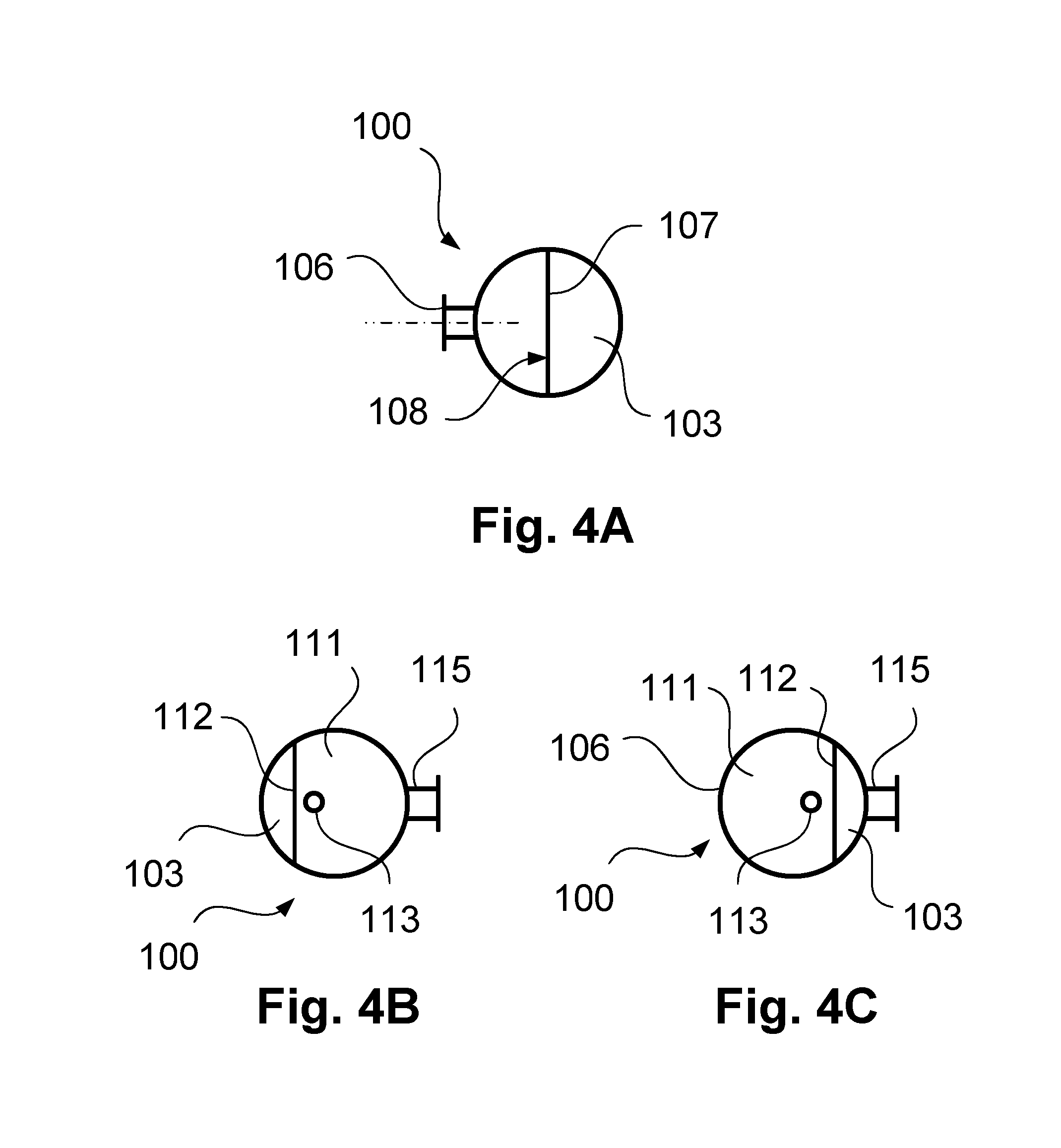
[0036] FIGS. 4a-4c show details of a pump reservoir according to one embodiment of the invention.
[0037] In the figures, corresponding elements bear identical reference signs and, for the sake of clarity, are not explained more than once.
DETAILED DESCRIPTION OF THE INVENTION
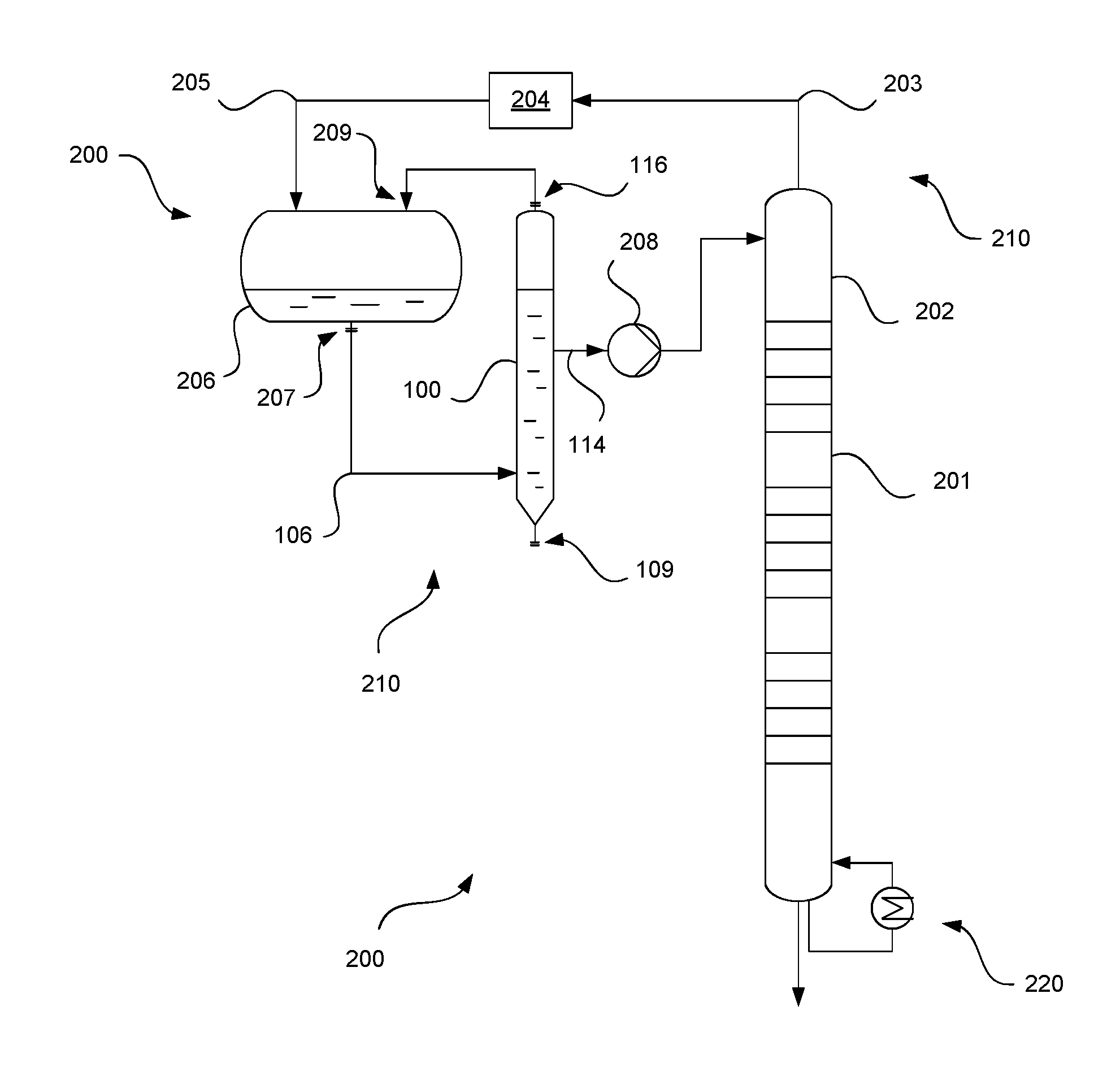
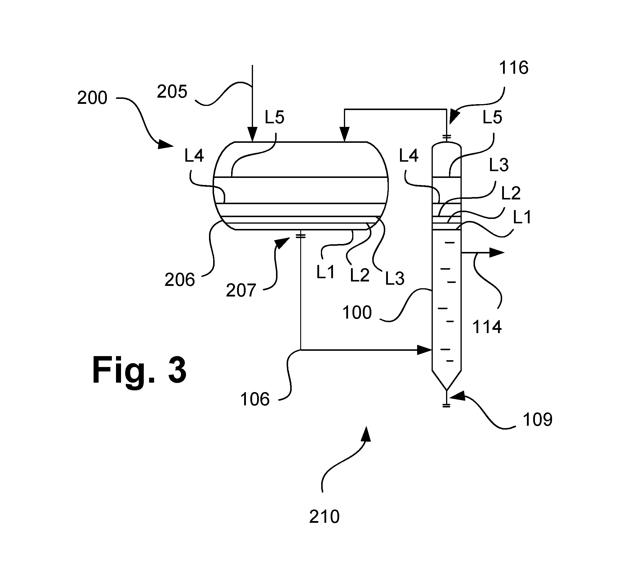
[0038] FIG. 1 schematically illustrates a rectification system according to a particularly preferred embodiment of the present invention and is denoted overall by 200.
[0039] The rectification system 200 comprises a rectification column 201, which is illustrated in a greatly simplified form. As explained, this serves the purpose of separating methane or a methane-containing gas mixture from an input mixture. For this purpose, the rectification column 201 has a top condenser of a type that is known in principle, which is denoted here overall by 210.
[0040] In the top condenser 210, a column top, denoted here by 202, of the rectification column 201 is connected by means of a line 203, which has also been referred to above as the "first line", to a suitable cooling device 204. The cooling device 204 may in particular comprise one or more heat exchangers, which are operated with a suitable coolant, for example expanded methane. The rectification column 201 may have a bottom evaporator 220, which however may be formed in a known way and is therefore not explained in detail for the sake of clarity.
[0041] In or downstream of the cooling device 204 there forms from a top gas rectification column 201 passed through the first line 203 a two-phase mixture, which is fed to a condensate separator 206 by way of a line 205, which has also been referred to above as the "second line". In the condensate separator 206, a condensate is separated and can be drawn off out of the condensate separator by way of a liquid removing opening 207.
[0042] The aim of the condensate separation is in particular to provide a liquid reflux, which can be returned by means of a pump 208 to the column top 202 of the rectification column 201. As explained above, it may happen here however that a corresponding condensate outgases and/or that solids are deposited. To avoid this, a pump reservoir 100 is used, shown here in a greatly simplified form and denoted overall by 100. A pump reservoir 100 that can be used according to one embodiment of the invention is explained in greater detail with reference to FIG. 2.
[0043] At least part of the condensate from the condensate separator 206 is in this case fed to the pump reservoir 100 by way of a liquid feeding opening 106, which is likewise illustrated more specifically in FIG. 2. In particular, one or more further liquid or gaseous streams may be removed from the condensate separator 206 by way of corresponding lines, in a way not illustrated here in detail. A fraction of the condensate that has evaporated in the pump reservoir 100 can be returned by way of a gas outlet 116 into the condensate separator 206 by way of a gas inlet 209. Depositing solids can be drawn off out of the pump reservoir 100 by way of a solids outlet 109. In this way it can be ensured that the pump is only fed a cryogenic liquid, without gaseous and solid fractions. This takes place by way of a liquid removing opening 114.
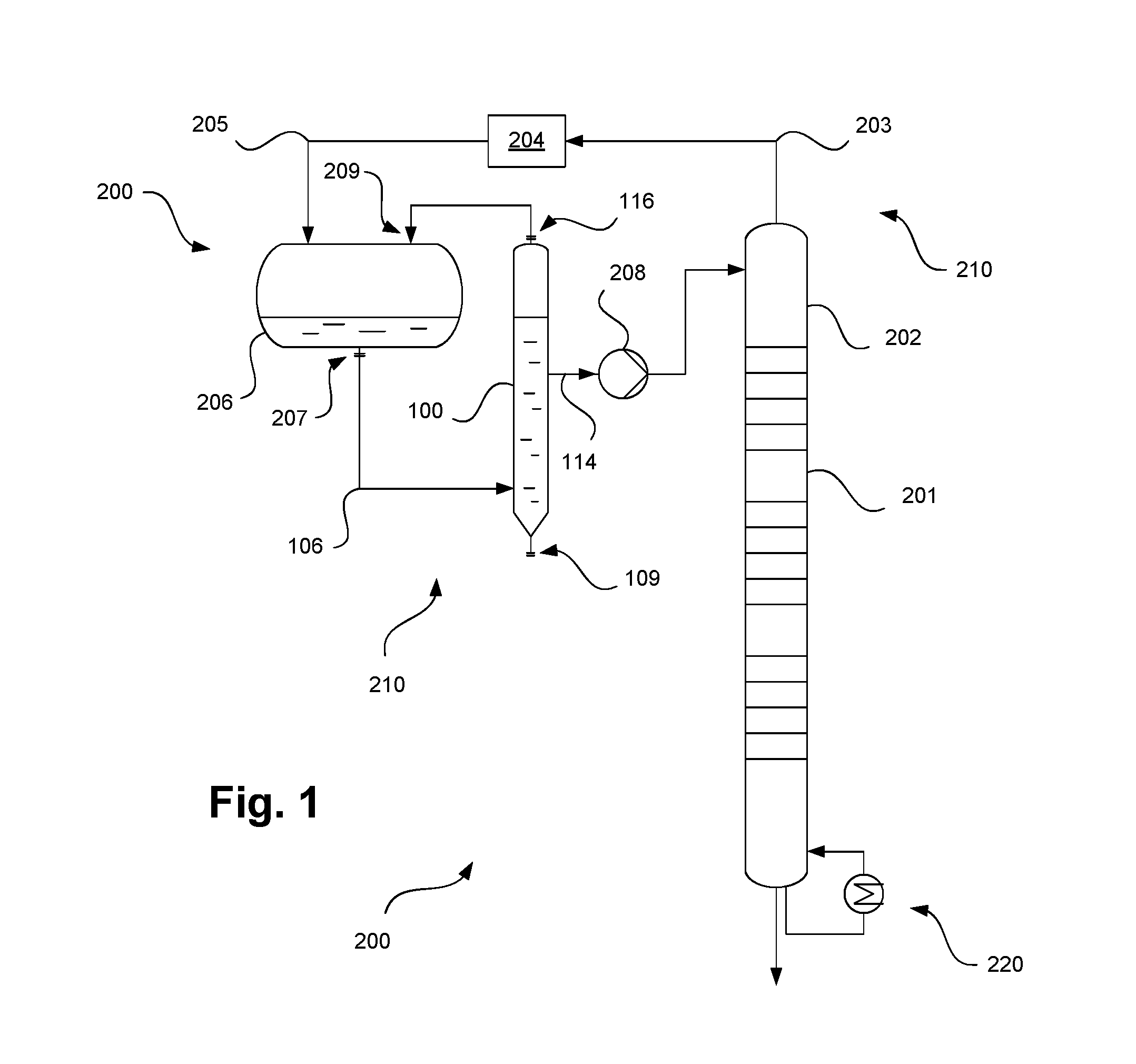
[0044] As already mentioned, a corresponding pump reservoir according to one embodiment of the invention is schematically illustrated in greater detail in FIG. 2 and is denoted overall by 100.
[0045] The pump reservoir 100 comprises an interior reservoir space 103, extending between a reservoir bottom 101 and a reservoir top 102. As illustrated by a dashed line, in particular the reservoir bottom 101 may be releasably attached by way of a suitable flange releasably to a shell that defines the interior reservoir space and is not separately denoted here. The interior reservoir space comprises a liquid feeding region 104, which is positioned at a first distance from the reservoir bottom 101 in the direction of the reservoir top 102, and a liquid removing region 105, which is positioned at a second distance from the reservoir bottom in the direction of the reservoir top. The second distance is in this case greater than the first distance, i.e. the liquid removing region 105 lies above the liquid feeding region 104 during the operation of the pump reservoir 100. Arranged in the liquid feeding region 104 is the liquid feeding opening 106, which has already been mentioned with reference to FIG. 1.
[0046] In the liquid feeding region 104, the interior reservoir space 103 is at least partially divided by means of a dividing wall 107, which is arranged in such a way that one of its surfaces, denoted here by 108, is aligned in the direction of the liquid feeding opening 106. Furthermore, in the example presented, the reservoir bottom 101 tapers in a direction away from the interior reservoir space 103 and has a solids outlet 109, which has likewise already been mentioned and shown in FIG. 1.
[0047] As illustrated in the form of a dotted liquid flow, liquid fed in by way of the liquid feeding opening 106 is backed up at the surface 108 of the dividing wall 107 that is aligned in the direction of the liquid feeding opening 106. Part of the liquid flows under the dividing wall 108 back in the direction of the reservoir bottom 101, and from there into the interior reservoir space 103. Another part flows directly in the direction of the reservoir top into the interior reservoir space 103. In this way, as mentioned, dead volumes in the reservoir bottom 101 can be avoided. As mentioned, the avoidance of corresponding dead volumes or dead zones is advantageous in particular because a precipitation of carbon dioxide caused by evaporating methane can be reduced in this way. Nevertheless, carbon dioxide precipitating in a solid state collects in the reservoir bottom 101, which is in particular conically formed, and can be drawn off out of it by way of the solids outlet 109. It goes without saying here that the reservoir bottom is at least partially not divided by means of the dividing wall 107.
[0048] As likewise mentioned, attached to the liquid feeding opening 106 is a liquid feeding line with a line axis, which is illustrated here in a dash-dotted manner. As likewise already mentioned, the term "line axis" should be understood here in the geometrical sense, not in the mechanical sense. The line axis runs in particular through the center point of the cross section of the line, which is typically of a circular form. The dividing wall 107 is in this case aligned in particular perpendicularly to line axis of the liquid feeding line, or the part thereof that opens out into the pump reservoir, i.e. the surface 108 of the dividing wall 107 that is oriented in the direction of the liquid feeding opening 106 is arranged in particular at an angle of 80 to 100.degree., in particular perpendicularly, to the line axis. In other words, the surface 108 of the dividing wall 107 faces the liquid feeding opening 106. As likewise mentioned, the dividing wall 107 is in particular arranged centrally in the interior reservoir space, in the liquid feeding region, i.e. the interior reservoir space, which has a specific cross section in the liquid region, for example a circular cross section, is divided into two halves, the area content of which is preferably identical, but in particular differs by no more than 20%.
[0049] Between the liquid feeding region 104 and the liquid removing region 105 there is formed in the pump reservoir 100 or its interior reservoir space 103 a gas collecting region 110, which serves in particular for allowing liquid to be removed without gas from the liquid removing region. For this purpose, the interior reservoir space 103 has in the gas collecting region 110 gas collecting trays 111. These gas collecting trays are respectively provided with gas collecting structures 112, which are aligned in the direction of the reservoir bottom 101. The gas collecting trays 111 also respectively bear gas lines 113, which run in the direction of the reservoir top. In the example shown, the gas collecting structures 112 that are attached to the gas collecting trays 111 take the form of noses, whereby the gas collecting trays together with these gas collecting structures are formed in the manner of wells that open in the direction of the reservoir bottom 101.
[0050] Gas bubbles rising up in the liquid in the interior reservoir space 103 collect in these wells and can in each case be carried away upward by way of the gas lines 113. As also further explained below, the arrangement of the gas collecting trays 111 with the gas collecting structures 112 and the gas lines 113 is in this case in particular such that corresponding gas bubbles can be passed through the liquid removing region 105 without it being possible for them to be drawn off by way of the liquid removing opening 114 and thereby damage the pump 218.
[0051] The mentioned liquid removing opening 114, which may in particular have a vortex breaker 115 in its mouth, opens out in the liquid removing region 105.
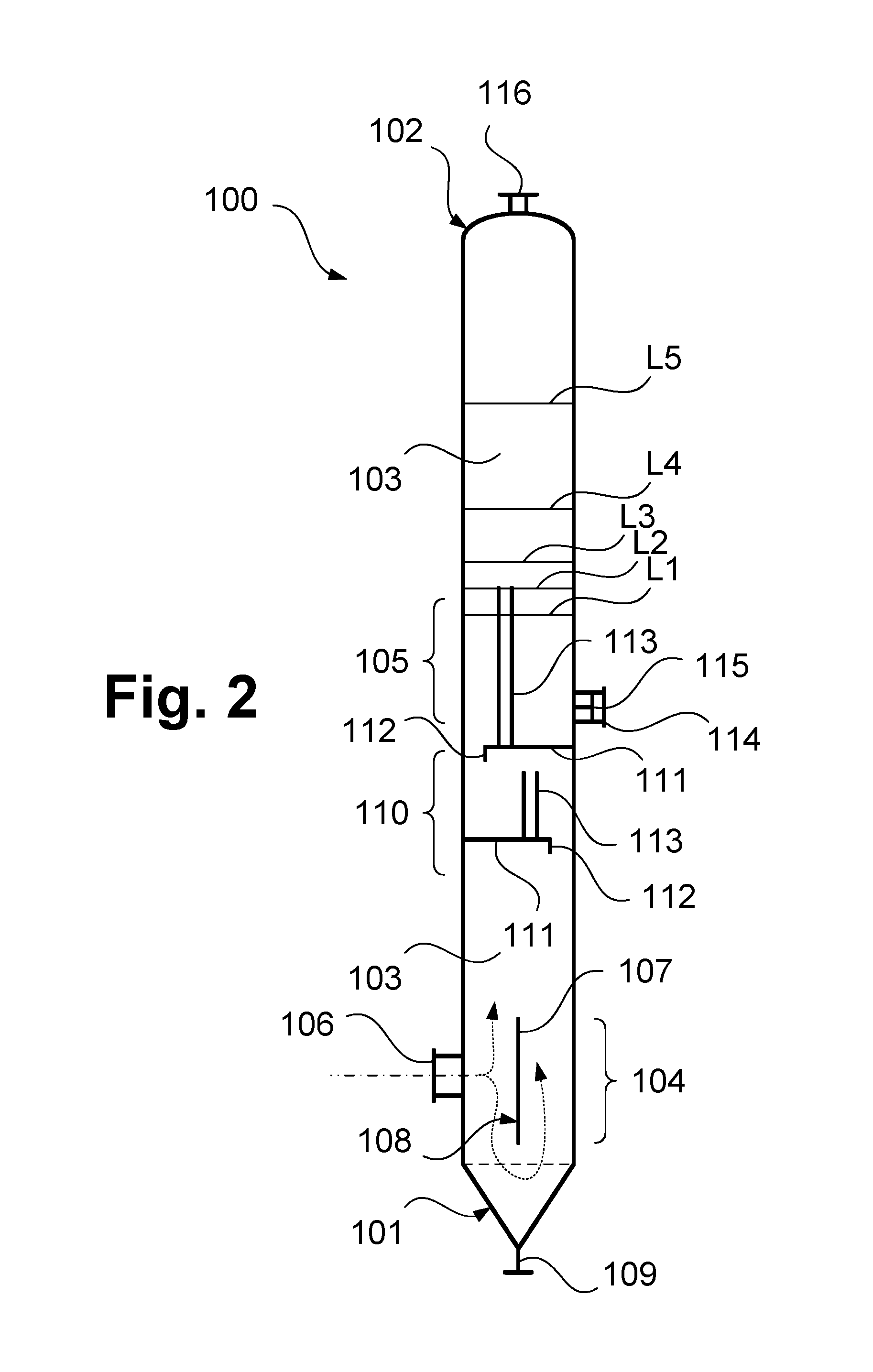
[0052] As illustrated by various liquid levels L1-L5, the liquid may be at different heights in the interior liquid space. These depend on a corresponding filling level in the condensate separator 206. The minimum filling level is denoted by L1, the maximum by L5. The gas lines of the gas collecting trays in this case open out above the liquid removing region 105, which lies below the minimum liquid level L1, and below or above corresponding liquid levels. Gas can be removed from a gas space above the liquid levels L1-L5 by way of the mentioned gas outlet 116.
[0053] In FIG. 3, the matter just mentioned of different liquid levels is illustrated once again. FIG. 3 shows here a partial view of FIG. 1; the explanations given there apply correspondingly.
[0054] FIGS. 4A-4C illustrate the column internals already shown in FIG. 2 once again in the form of cross-sectional views through the liquid feeding region 104 (FIG. 4A) and the gas collecting region 110 (FIGS. 4B and 4C).
[0055] As can be seen from FIG. 4A, a cross section of the interior reservoir space 103 in the liquid feeding region 104 is substantially circular. The interior reservoir space is in this case divided into two halves by the dividing wall and the dividing wall 107 is arranged in such a way that its surface 108 that is oriented in the direction of the liquid feeding opening 106 is arranged at an angle perpendicularly to the line axis of the liquid feeding opening 106. Even though a circular cross section of the interior reservoir space 103 is shown in the example presented, it goes without saying that this cross section can also deviate from a circular cross section to the extent claimed. Of course, the same also applies correspondingly to the orientation of the dividing wall 107.
[0056] In the cross-sectional representations of FIGS. 4B and 4C, cross sections through the gas collecting region 110 are respectively illustrated above a gas collecting tray 111 in each case. As can be seen, the gas collecting trays 111 in this case cover the cross section of the reservoir by over half in each case, and the gas collecting trays 111 are arranged at different positions offset in relation to one another. In this way it is ensured that, over the entire cross section of the pump reservoir 111, gas bubbles rising up can be collected and taken past the liquid removing region 105 by way of the corresponding gas lines 113.
* * * * *
D00000
D00001
D00002
D00003
D00004
XML
uspto.report is an independent third-party trademark research tool that is not affiliated, endorsed, or sponsored by the United States Patent and Trademark Office (USPTO) or any other governmental organization. The information provided by uspto.report is based on publicly available data at the time of writing and is intended for informational purposes only.
While we strive to provide accurate and up-to-date information, we do not guarantee the accuracy, completeness, reliability, or suitability of the information displayed on this site. The use of this site is at your own risk. Any reliance you place on such information is therefore strictly at your own risk.
All official trademark data, including owner information, should be verified by visiting the official USPTO website at www.uspto.gov. This site is not intended to replace professional legal advice and should not be used as a substitute for consulting with a legal professional who is knowledgeable about trademark law.