Heat Exchange Cell For A Heating Boiler
GIANNONI; Rocco ; et al.
U.S. patent application number 16/283005 was filed with the patent office on 2019-09-12 for heat exchange cell for a heating boiler. This patent application is currently assigned to CONDEVO S.P.A.. The applicant listed for this patent is CONDEVO S.P.A.. Invention is credited to Remo CASTELLI, Rocco GIANNONI.
| Application Number | 20190277536 16/283005 |
| Document ID | / |
| Family ID | 62386847 |
| Filed Date | 2019-09-12 |


View All Diagrams
| United States Patent Application | 20190277536 |
| Kind Code | A1 |
| GIANNONI; Rocco ; et al. | September 12, 2019 |
HEAT EXCHANGE CELL FOR A HEATING BOILER
Abstract
A heat exchange cell for a heating boiler includes a casing with a sidewall enclosing an internal space, the sidewall having an open front end surrounded by an annular edge of the casing front end. A sheet metal annular closing flange has an opening and radially internal, intermediate and external flange edges. The radially external flange edge connects to the casing sidewall along the annular edge. The radially internal edge defines radially internal and external surfaces. A front edge surface connects the radially internal surface and radially external surface. The front edge surface defines a lying plane on which the front edge surface lies, the lying plane defining an axial direction orthogonal to the lying plane and passing through the opening, and a radial direction orthogonal to the axial direction. The radially internal surface extends parallel to the axial direction protruding towards an outside of the cell.
| Inventors: | GIANNONI; Rocco; (Milano, IT) ; CASTELLI; Remo; (Milano, IT) | ||||||||||
| Applicant: |
|
||||||||||
|---|---|---|---|---|---|---|---|---|---|---|---|
| Assignee: | CONDEVO S.P.A. Milano IT |
||||||||||
| Family ID: | 62386847 | ||||||||||
| Appl. No.: | 16/283005 | ||||||||||
| Filed: | February 22, 2019 |
| Current U.S. Class: | 1/1 |
| Current CPC Class: | F28F 2230/00 20130101; F28D 2021/0024 20130101; F24H 9/02 20130101; F24H 1/43 20130101; F28F 9/00 20130101; F24H 9/148 20130101; F28F 1/02 20130101; F24B 13/004 20130101; F24H 9/146 20130101; F28D 7/024 20130101 |
| International Class: | F24H 1/43 20060101 F24H001/43; F24H 9/02 20060101 F24H009/02; F24H 9/14 20060101 F24H009/14 |
Foreign Application Data
| Date | Code | Application Number |
|---|---|---|
| Mar 12, 2018 | IT | 102018000003444 |
Claims
1. A heat exchange cell for a heating boiler, comprising: a casing comprising a side wall enclosing an internal space, said side wall having an open front end surrounded by an annular edge of the front end of the casing, an annular closing flange made from a sheet metal having a flange through opening to allow the access to the inside of the casing, said closing flange defining a radially internal flange edge surrounding said through opening, a radially external flange edge arranged around said radially internal edge, an intermediate flange portion connecting the radially external flange edge and the radially internal flange edge to one another, said radially external flange edge being connected to said side wall of the casing along said annular edge of the front end of the casing, wherein said radially internal edge defines a radially internal surface, a radially external surface arranged around said radially internal surface, a front edge surface connecting said radially internal surface and said radially external surface to one another, said front edge surface defining a lying plane on which said front edge surface lies, said lying plane defining an axial direction orthogonal to the lying plane and passing through the through opening, and a radial direction orthogonal to the axial direction, wherein said radially internal surface extends parallel to the axial direction in a manner protruding towards the outside of the cell with respect to said intermediate flange portion.
2. A cell according to claim 1, wherein a cross-section orthogonal with respect to the axial direction of the radially internal surface is constant along the axial direction.
3. A cell (1) according to claim 1, wherein the radially internal surface and the radially external surface are defined by two respective sheet metal portions, folded with one another in a superimposed double layer.
4. A cell according to claim 1, wherein said flange is entirely formed in one piece from a single piece of sheet metal by plastic deformation.
5. A cell according to claim 1, comprising: a heat exchanger mounted inside the casing, said exchanger comprising at least one tubular duct helically wound about a helix axis arranged along the axial direction, forming a plurality of coils, said plurality of coils ending with an end helical coil facing towards said closing flange; wherein said intermediate annular flange portion is shaped to adhere with continuity to said end helical coil.
6. A cell according to claim 5, wherein said intermediate annular flange portion is shaped according to a single helicoid ring joined at ends of the ring by a step portion.
7. A cell according to claim 6, wherein the closing flange comprises axial protrusions extending from the radially internal edge towards inside of the cell, wherein the axial protrusions form a centering of the exchanger with respect to said closing flange.
8. A cell according to claim 1, wherein the closing flange comprises at least one flat portion extending from the radially external edge towards the radially internal edge, said flat portion lying on a plane orthogonal to the axial direction, wherein each of said at least one flat portions is adapted to support a respective fastening pin to fasten the door to the closing flange, arranged according to the axial direction.
9. A cell according to claim 5, wherein the intermediate flange portion comprises at least one annular channel internally facing the cell, adapted to receive a sealing material interposed between the intermediate flange portion and the end helical coil of the exchanger.
10. A cell according to claim 1, comprising a door configured to be removably fastened to said closing flange to close said through opening, said door comprising a disc comprising a refractory insulating material, said disc being delimited by a side disc surface; wherein the radially internal surface is configured to surround and externally embrace the side disc surface and to allow axial sliding thereof.
11. A cell according to claim 10, comprising a thermal barrier device and a fume seal device, separate from one another and interposed between said closing flange and said door along said radially internal edge.
12. A cell according to claim 11, wherein the thermal barrier device is interposed, in the axial direction, between said front edge surface and said door.
13. A cell according to claim 12, wherein the fume seal device is interposed, in the radial direction, between the radially external surface of the closing flange and a peripheral radial seal edge of said door.
14. A cell according to claim 12 or 13, wherein the thermal barrier device comprises, an annular peripheral protrusion of said disc, protruding, in the radial direction, from the side surface of said disc, said annular peripheral protrusion forming an abutment surface lying on a plane orthogonal to the axial direction and configured to axially adhere to said front edge surface of the closing flange.
15. A cell according to claim 11, wherein the thermal barrier device is interposed, in the radial direction, between the radially internal surface of the closing flange and said door.
16. A cell according to claim 15, wherein the fume seal device is interposed, in the axial direction, between the front edge surface and the door.
17. A cell according to claim 11, wherein the thermal barrier device comprises a gasket, selected among a ceramic fiber cord gasket, or a glass fiber cord gasket, or a graphite gasket.
18. A cell according to claim 11, wherein the fume seal device comprises a gasket selected between a rubber gasket or a silicone gasket.
Description
[0001] This application claims benefit of Serial No. 102018000003444, filed 12 Mar. 2018 in Italy and which application is incorporated herein by reference. To the extent appropriate, a claim of priority is made to the above disclosed application.
FIELD OF THE INVENTION
[0002] The present invention relates to a heat exchange cell for a boiler intended for heating, which finds a preferred but not exclusive employment in water-heating appliances, in heating or air-conditioning systems, intended for domestic use or in housing complexes, industrial or commercial spaces.
[0003] "Heat exchange cell" means a unit comprising at least one heat exchanger mounted in a respective containment casing and configured to actuate a heat exchange between a first heat-transfer fluid circulating inside the exchanger, and a second heat-transfer fluid circulating inside the containment casing.
[0004] For example, the heat exchanger is of the type comprising a duct wound in a spiral on a plurality of overlapping coils adapted to be traversed by the first heat-transfer fluid which is then circulated in the heating system, and in which such duct forms a central space in which a combustion occurs, adapted to heat the second heat-transfer fluid.
BACKGROUND ART
[0005] In the heating boiler industry, the employment of a heat exchange cell comprising a containment casing and a heat exchanger mounted thereinside is well known.
[0006] The use of an exchanger comprising a duct, or tube, wound in a spiral according to a plurality of overlapping coils so as to form an internal or central space adapted to host a combustion is also known.
[0007] Such exchanger has a front end coil facing towards the outside of the casing and an opposite back end coil, which, in use, faces towards the inside of the casing. The front end coil, therefore, has a front surface which is not flat but helical.
[0008] During the assembly, the exchanger is inserted into the casing, which is closed by means of a closing flange having a central opening aligned with the internal space so as to allow access to the exchanger for maintenance operations.
[0009] Some embodiments are known in which the flange comprises elements made from a molded sheet metal, assembled to one another so as to take advantage of the thermal inertia of the sheet metal which is lower with respect to that of an element obtained by die-casting, by virtue of the reduced thickness thereof.
[0010] A known cell further comprises a closing door adapted to be mounted to the casing, in particular to the flange, to close the opening while in use.
[0011] The door comprises a disc made from refractory insulating material, centrally fastened with respect thereto. Such disc is configured to be arranged, in use, into the opening of the flange near the radially internal edge of the flange.
[0012] A heat exchange cell is known having a flange having a main body made from a sheet metal, having a radially internal edge arranged around the flange opening, a radially external edge fastened to the casing, and an intermediate flange portion which connects them to one another, wherein the intermediate portion is flat and orthogonal to a flange axis.
[0013] The radially internal edge is flat and lying on a plane orthogonal to the flange axis.
[0014] To allow the door to close the opening, it has a face adapted to be facing towards, and in abutment against, the radially internal edge of the flange, also.
[0015] To obtain a seal between the flange and the door, the aforesaid embodiment according to the background art requires the use of at least one annular gasket which remains axially interposed, and axially pressed, between the flange and the door.
[0016] Such gasket, according to the background art, may not be interposed between the insulating disc and the flange, since the planarity of the radially internal edge and the orthogonality thereof with respect to the flange opening axis do not allow the gasket to be interposed radially between the edge and the insulating disc, but only axially between the flange and the door.
[0017] Thereby, a high amount of heat is transmitted from the combustion area to the radially internal edge of the flange, since no gasket may be interposed therein. On the contrary, according to the background art, the gasket may only be arranged in a position more external radially with respect to the radially internal edge. Such a solution, therefore, does not allow the radially internal end of the internal edge of the flange to be protected from the high temperatures reached by the combustion. Such edge, in fact, remains directly exposed towards the combustion chamber.
[0018] The at least one gasket is arranged near such internal edge, and, therefore, in an area with high thermal stress.
[0019] This produces a rapid deterioration of the gasket itself. The need is therefore felt to provide a heat exchange cell which allows to thermally insulate the door from the combustion area in a manner more efficient with respect to the background art. At the same time, the need is felt to further protect both the thermal barrier and the fume seal from the high thermal stresses.
[0020] For the cell to properly operate, a fume seal shall be provided between the front end coil and the internal surface of the flange.
[0021] To this end, the internal surface of the flange shall adhere to the front end coil.
[0022] However, in an exchanger wound according to a plurality of helical coils, also the front end coil is helical, thus offering a surface facing on the front towards the flange which is not flat but is shaped according to a helicoid.
[0023] For the surface of the flange facing towards such surface of the front end coil to provide a seal therewith, it shall adhere thereto.
[0024] An attempt is known to solve this problem by means of an additional element shaped as a helicoid, separated from the flange and fastened to the flange in a manner spaced therefrom.
[0025] Such additional element allows to provide a seal between the end coil and the additional element itself, but is not free from disadvantages.
[0026] For example, this background art with additional element requires to provide a remarkably complicated flange structure, in which the additional element is manufactured separately and subsequently fastened to the flange. This directly translates into high production costs. However, worse than that, this increases the mass of the flange-element assembly, increasing the thermal inertia thereof, which negatively affects the thermal efficiency of the cell. In fact, since the additional element is separated from the flange, it does not contribute to the optimal cooling of the end coil, but only provides the fluid seal between the combustion area and the peripheral space arranged externally to the exchanger.
[0027] Another attempt, known to make the surface of the front end coil adhere to the flange, is to deform the end coil by modifying the straight section along the development axis of the coil so as to provide a flat shape to a wall portion of the coil facing towards, and in contact with, the flat flange.
[0028] The variation of the straight section of the front end coil negatively affects the flow of the fluid passing through it, moving the flow behavior away from the laminar motion. In fact, due to the section variation, the fluid is subjected to variations in speed and pressure along the path thereof, which may lead to turbulent motion, load loss, or cavitation. These effects result in a reduction in the thermal efficiency of the cell. Furthermore, the execution of an end coil deformation step is an indisputable additional production cost.
[0029] The need is therefore felt to improve the thermal efficiency of a heat exchange cell having a flange made from a sheet metal, limiting the production costs of the cell itself.
[0030] In particular, none of these known solutions proposes a heat exchange cell having a flange made from a sheet metal which allows to satisfy all the aforesaid requirements at the same time, and, specifically, to improve the thermal insulation of the door with respect to that of the combustion area, protecting both the thermal barrier and the fume seal from the high thermal stresses, thus extending the useful life thereof, and to improve the thermal efficiency of the cell, while still minimizing production costs.
SUMMARY OF THE INVENTION
[0031] It is the object of the present invention to devise and provide a heat exchange cell which allows to satisfy the aforesaid requirements and to obviate at least partially the drawbacks complained here above with reference to the background art.
[0032] In particular, it is an object of the present invention to provide a heat exchange cell having a flange made from a sheet metal which allows to thermally insulate the door from the combustion area in a manner more efficient with respect to the background art.
[0033] It is also an object of the present invention to provide a heat exchange cell which allows to further protect both the thermal barrier and the fume seal from the high thermal stresses originating from the combustion area. It is another object of the present invention to provide a heat exchange cell capable of improving the thermal efficiency of the cell itself.
[0034] It is a further object of the present invention to provide a heat exchange cell capable of limiting the production costs of the cell itself.
[0035] It is also the object of the present invention to provide a heat exchange cell having a flange made from a sheet metal which allows to satisfy all the aforesaid requirements at the same time, and, specifically, to improve the thermal insulation of the door with respect to that of the combustion area, protecting both the thermal barrier and the fume seal from the high thermal stresses, thus extending the useful life thereof, and to improve the thermal efficiency of the cell, while still minimizing production costs.
BRIEF DESCRIPTION OF THE DRAWINGS
[0036] The invention will be illustrated below with the description of some embodiments thereof, given by way of explanation and not by way of limitation, with reference to the accompanying drawings in which:
[0037] FIG. 1 shows an exploded view of a heat exchange cell in accordance with the invention;
[0038] FIG. 2 shows a front view of a closing flange of the cell of FIG. 1;
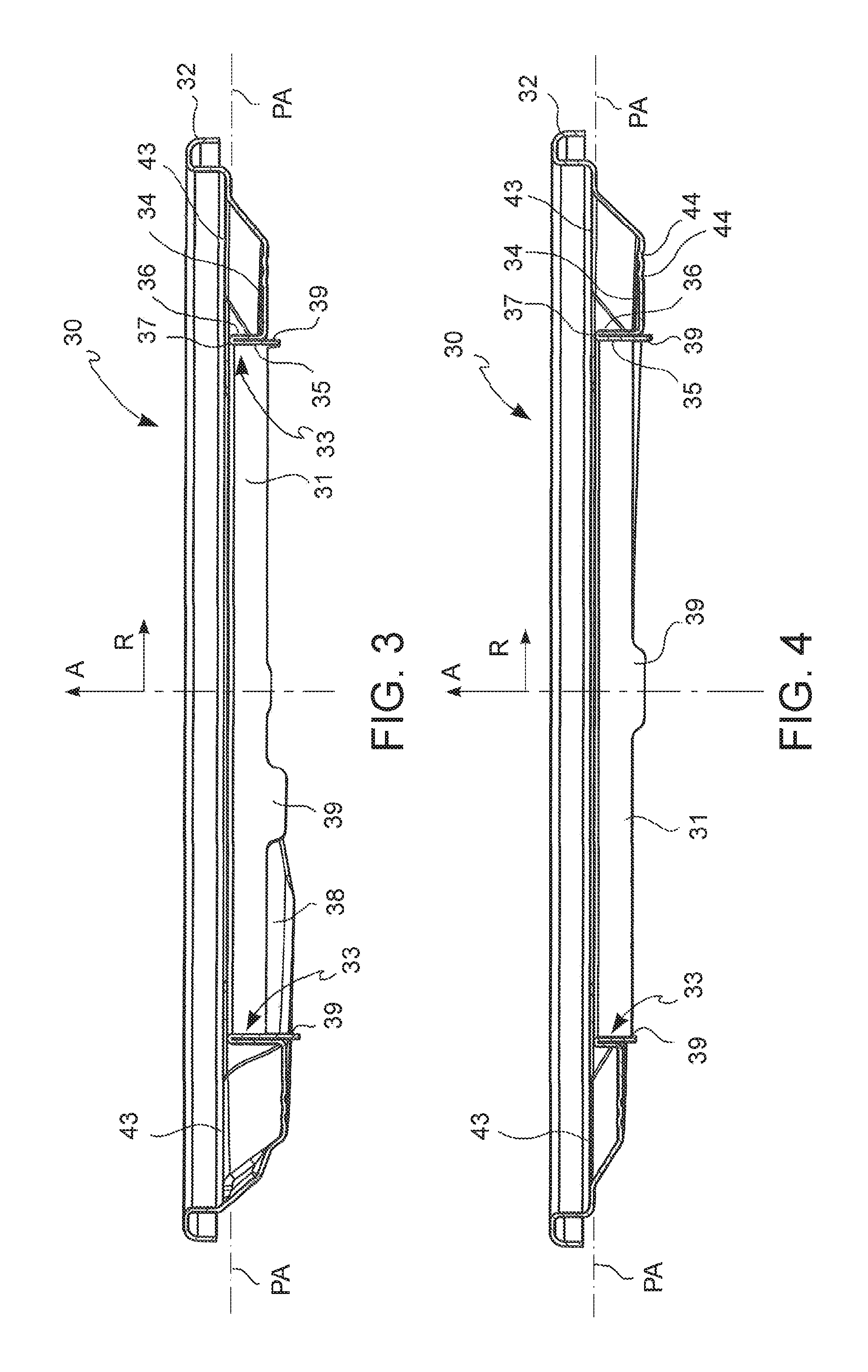
[0039] FIG. 3 shows a sectional view of the flange of FIG. 2, by means of a section plane III comprising the main axis, shown in FIG. 2;
[0040] FIG. 4 shows a sectional view of the flange of FIG. 2, by means of a section plane IV comprising the main axis, shown in FIG. 2;
[0041] FIGS. 5 and 6 respectively show two perspective views of the flange of FIG. 2 from two different angles;
[0042] FIG. 7 shows a partial sectional view of an assembly of the flange of FIG. 2 and of a heat exchanger associated with the flange, by means of a section plane VII comprising the main axis, shown in FIG. 8;
[0043] FIG. 8 shows a front view of the assembly of FIG. 7;
[0044] FIG. 9 shows a partial sectional view of the assembly of FIG. 8, by means of a section plane IX comprising the main axis, shown in FIG. 8;
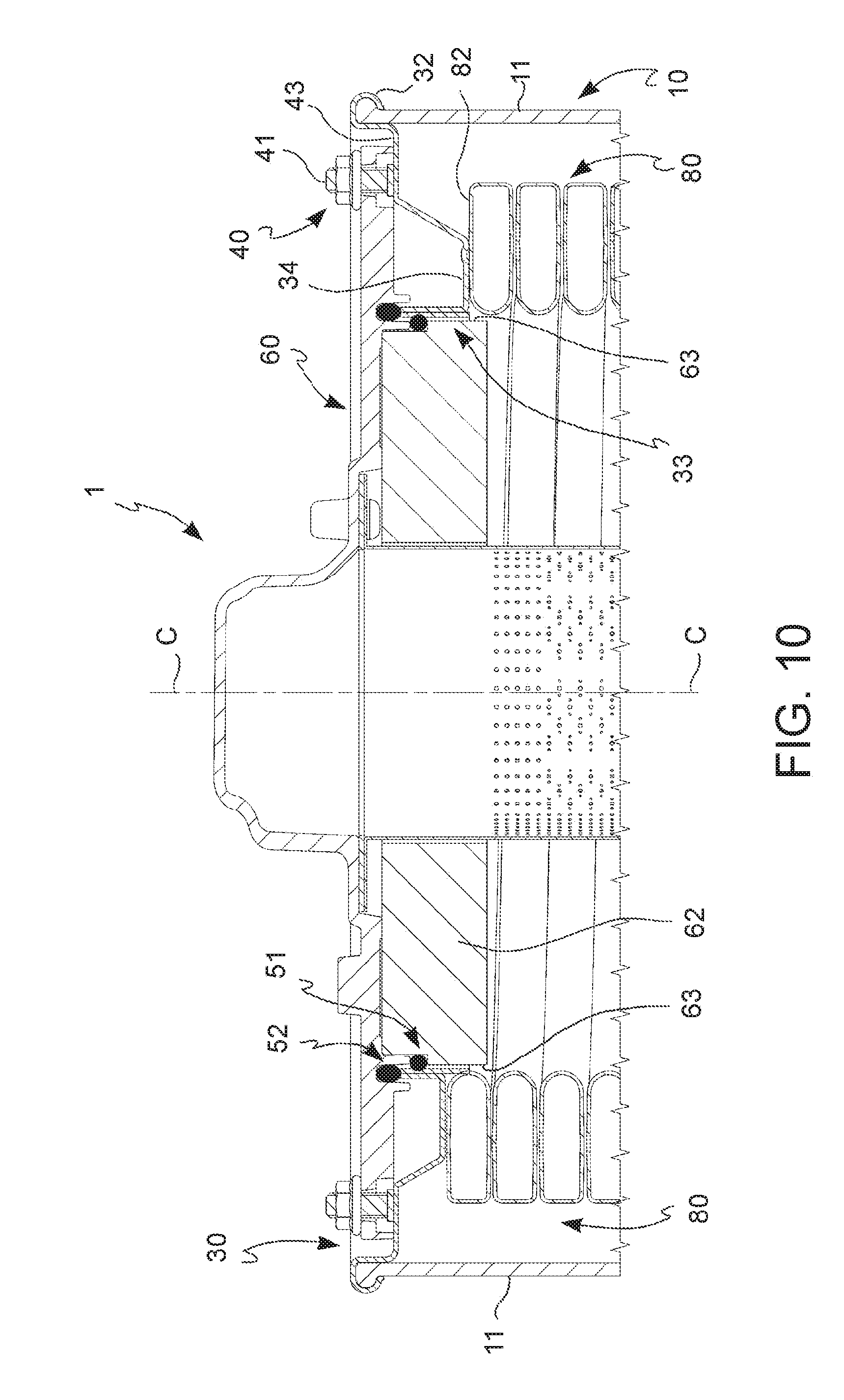
[0045] FIG. 10 shows a partial sectional view of the cell of FIG. 1 by means of a section plane comprising the main axis, in which casing, flange, door, exchanger are shown, in accordance with an embodiment of the invention;
[0046] FIG. 11 shows a partial sectional view of a detail of the cell by means of a section plane comprising the main axis, in accordance with an embodiment of the invention;
[0047] FIG. 12 shows a partial sectional view of a detail of the cell by means of a section plane comprising the main axis, in accordance with another embodiment of the invention;
[0048] FIG. 13 shows a partial sectional view of a detail of the cell by means of a section plane comprising the main axis, in accordance with a further embodiment of the invention;
[0049] FIG. 14 shows a partial sectional view of a detail of the cell by means of a section plane comprising the main axis, in which an axial thermal barrier device, formed by an abutment portion, is present in the door plate, adapted to be placed in abutment and to adhere to the front edge surface of the radially internal edge according to the axial direction, and in which a fume seal device is present, radially housed around the radially external surface of the radially internal edge;
[0050] FIG. 15 shows a partial sectional view of a detail of the cell by means of a section plane comprising the main axis, in which the thermal barrier device is housed in an annular slot radially open towards the outside, interposed between the side surface of the disc and the door plate and arranged near the front edge surface, and in which a fume seal device is present, radially housed around the radially external surface of the radially internal edge;
[0051] FIG. 16 shows a partial sectional view of a detail of the cell by means of a section plane comprising the main axis, in which the thermal barrier device is housed in an annular radial slot radially open towards the outside, interposed between the side surface of the insulating disc and the door plate and arranged in an axially intermediate position of the radially internal surface of the radially internal edge, and in which a fume seal device is present, housed in an annular groove in the door plate axially entering the door plate;
[0052] FIG. 17 shows a partial sectional view of a detail of the cell by means of a section plane comprising the main axis, in which the thermal barrier device is obtained by means of an annular tooth radially protruding towards the outside of the insulating disc, adapted to abut against the front edge surface of the radially internal edge of the flange, and in which a fume seal device is present, housed in an annular groove in the door plate axially entering into the door plate from an annular edge axially protruding from the door plate.
DESCRIPTION OF THE PREFERRED EMBODIMENTS
[0053] With reference to the Figures, a heat exchange cell for a heating boiler in accordance with the invention is generally indicated with reference numeral 1.
[0054] The heat exchange cell 1 comprises a casing 10 comprising a side wall 11 enclosing an internal space, said side wall 11 having an open front end 14 surrounded by an annular edge 15' of the front end of the casing. The cell further comprises an annular closing flange 30 made from a sheet metal having a flange through opening 31 to allow the access to the inside of the casing 10.
[0055] The closing flange 30 defines a radially internal flange edge 33 surrounding the through opening 31, a radially external flange edge 32 arranged around the radially internal edge 33, an intermediate flange portion 34 connecting the radially external flange edge 32 and the radially internal flange edge 33 to one another. The radially internal edge 33 has an annular shape, preferably circular.
[0056] The radially external edge 32 has an annular shape, preferably circular or polygonal, preferably with rounded vertices.
[0057] The radially external flange edge 32 is connected to the side wall 11 of the casing along the annular edge 15' of the front end of the casing.
[0058] In accordance with an embodiment, the cell comprises a door 60 configured to be removably fastened to said closing flange 30 to close the through opening 31, the door 60 comprising an insulating disc 62 comprising a refractory insulating material.
[0059] The door 60 may comprise a door plate 61, preferably made of metal, on which the insulating disc 62 is fastened. The insulating disc 62 is delimited by a side disc surface 63.
[0060] The radially internal edge 33 defines a radially internal surface 35, a radially external surface 36 arranged around the radially internal surface 35, a front edge surface 37 connecting said radially internal surface 35 and said radially external surface 36 to one another. In accordance with an embodiment, the radially internal surface 35 is configured to surround and to externally embrace the side disc surface 63 and to allow an axial sliding of said disc 62 with respect to said radially internal surface 35.
[0061] The front edge surface 37 lies on a lying plane PA. Such lying plane PA defines an axial direction A orthogonal to the lying plane PA and a radial direction R orthogonal to the axial direction A.
[0062] The axial direction A is arranged passing through the opening 31.
[0063] The radially internal surface 35 extends parallel to the axial direction A in a manner protruding towards the outside of the cell 1 with respect to said intermediate flange portion 34.
[0064] In other words, the radially internal edge 33 is shaped as a collar extending in the axial direction A towards the outside of the cell 1.
[0065] Again in other words, the radially internal edge 33 has a tubular or a sleeve shape, with an axis arranged according to the axial direction A, and defined by the radially internal surface 35 and by the radially external surface 36, and axially ending towards the outside with the front edge surface 37.
[0066] In accordance with an embodiment, the radially internal surface 35 of the radially internal edge 33 and the side surface 63 of the insulating disc 62 are complementary to one another and radially arranged, in use, at a minimum distance from one another when the door 60 is mounted on the flange 30.
[0067] In accordance with an embodiment, the cross-section orthogonal with respect to the axial direction A of the radially internal surface 35 is constant along the axial direction A.
[0068] In accordance with an embodiment, the radially internal surface 35 is substantially cylindrical, or prismatic, with a central axis arranged according to the axial direction A. Preferably, also the side surface 63 of the insulating disc 62 is substantially cylindrical, or prismatic, with the central axis arranged according to the axial direction A.
[0069] In accordance with an embodiment, the radially internal surface 35 and the radially external surface 36 are defined by two respective sheet metal portions, folded with one another in a superimposed double layer. Such two sheet metal portions are, for example, cylindrical.
[0070] In accordance with another embodiment, the radially internal surface 35 and the radially external surface 36 are defined by two opposite faces of a single sheet metal portion.
[0071] In accordance with an embodiment, the radially external surface 36 surrounds the radially internal surface 35 and is parallel to the radially internal surface 35. In accordance with an embodiment, as shown, for example, in FIGS. 11-13, the cell 1 comprises a thermal barrier device 51 and a fume seal device 52, separate from one another and interposed between the closing flange 30 and the door 60 along the radially internal edge 33. The presence of two distinct devices, respectively, a thermal barrier and a seal device, allows to optimize the specific features required for both.
[0072] In accordance with some embodiments, shown in FIGS. 12 and 13, the thermal barrier device 51 is interposed in the axial direction A between the front edge surface 37 and the door 60.
[0073] In other words, the thermal barrier device is arranged at an external end of the radially internal edge, opposite to an end thereof facing towards the combustion area. Since the radially internal surface embraces the side surface of the insulating disc, the latter partially protects it from thermal stress. By virtue of this arrangement, the temperature of the radially internal edge, at the axially external end thereof, is lower than the temperature thereof at the axially internal end thereof. Consequently, the thermal barrier device 51 is partially protected by means of the insulating disc 62.
[0074] In accordance with an embodiment, for example, shown in FIG. 12, the thermal barrier device 52 comprises, or is formed by, an annular peripheral protrusion 66 of the disc 62, protruding in the radial direction R from the side surface 63 of said insulating disc 62.
[0075] Such annular protrusion 66, may be made in one piece with the insulating disc 62.
[0076] The annular peripheral protrusion 66 forms an abutment surface 64 lying on a plane orthogonal to the axial direction A and configured to axially adhere to the front edge surface 37 of the closing flange 30.
[0077] Thereby, the insulating disc 62 itself operates as a thermal barrier, allowing to avoid the use of any other thermal barrier device.
[0078] As shown in FIGS. 12 and 13 themselves, the fume seal device 52 may be interposed in the radial direction R between the radially external surface 36 of the radially internal edge of the closing flange and a peripheral radial seal edge 65 of said door 60.
[0079] In other words, the fume seal device 52 is received by and/or fastened to the radially external surface 36 of the radially internal edge of the closing flange.
[0080] The feature of the radially internal surface 36 of embracing the side surface of the insulating disc 62 is also particularly advantageous so as protect the fume seal device from the high temperatures. In fact, the disc 62, whose side surface 63 is at a minimum distance from the radially internal surface 35, also protects the radially external surface 36 of the radially internal flange edge 33 on which the fume seal device 52 is mounted, from the high temperature.
[0081] In accordance with another embodiment, shown for example in FIG. 11, the thermal barrier device 51 is interposed in the radial direction R between the radially internal surface 35 of the closing flange 30 and the door 60.
[0082] Thereby, such thermal barrier device 51 is arranged axially upstream of the fume seal device 52.
[0083] The fume seal device 52 may be interposed, for example, in the axial direction A between the front edge surface 37 and the door 60.
[0084] Also in accordance with this embodiment, the feature of the radially internal surface 36 of embracing the side surface of the insulating disc 62 is also particularly advantageous so as protect the fume seal device from the high temperatures. In fact, the insulating disc 62, whose side surface 63 is at a minimum distance from the radially internal surface 35, also protects the radially external surface 36 of the radially internal flange edge 33 on which the fume seal device 52 is mounted, from the high temperature.
[0085] In accordance with an embodiment, the thermal barrier device 51 comprises a gasket 53, selected among a ceramic fiber cord gasket, or a glass fiber cord gasket, or a graphite gasket.
[0086] In accordance with an embodiment, the fume seal device 52 comprises a gasket 54 selected between a rubber gasket or a silicone gasket.
[0087] In accordance with an embodiment, the cell 1 comprises a heat exchanger 80 mounted inside the casing 10.
[0088] The exchanger 80 is of the type comprising at least one tubular duct 81 helically wound about a coincident helix axis arranged along the axial direction A according to a plurality of coils ending with a front end helical coil 82 facing towards said closing flange 30.
[0089] The intermediate annular flange portion 34 may be advantageously shaped so as to adhere with continuity to the front end helical coil 82.
[0090] Thereby, the flange 30, and in particular the intermediate flange portion 34, has a double function: facilitating the fume seal between the flange and the front end coil 82 of the exchanger 80, and cooling down the intermediate flange portion 34 by means of the contact with the front end coil 82.
[0091] In fact, such front end coil 82 is placed at the outlet of the exchanger and is traversed by a heated fluid, preferably water, which is then fed into the heating system.
[0092] Such heated fluid which traverses the front end coil 82 has a temperature of about 80-90.degree. C., which is much lower with respect to that of the central space of the exchanger in which the combustion occurs and which the door faces, which has a temperature of about 800-900.degree. C. Therefore, the adherence of the intermediate flange portion to the front end coil 82 allows to reduce the flange temperature from 800-900.degree. C. to 80-90.degree. C., thereby protecting the thermal barrier device and the fume seal device from the high temperatures.
[0093] In accordance with an embodiment, the intermediate annular flange portion 34 is shaped according to a single helicoid ring joined at the ends thereof by means of a step portion 38. FIG. 9 shows in cross-section an example of such step portion.
[0094] The axis of the helicoid is preferably arranged in the axial direction A, preferably coincident with the central axis of the casing C-C.
[0095] Such helicoid ring ends with a first end 34' in a position axially more external to the cell, and with a second end 34'' axially more internal to the cell, in which such first end 34' and second end 34'' are connected to one another by the step portion 38, preferably in a radiused manner.
[0096] In accordance with an embodiment, the tubular duct 81 has a constant cross-section along the extension thereof, in which such cross-section is flattened and has opposite upper 83 and lower sides 84 of the cross-section, evaluated according to the axial direction, substantially straight.
[0097] In such case, the intermediate annular flange portion 34 is shaped as a flat helicoid.
[0098] In accordance with an embodiment, for example, shown in FIG. 7, the diameter of the opening of the flange D1 is substantially equal to the internal diameter D2 of the exchanger.
[0099] In accordance with an embodiment, for example, as shown in FIGS. 11-13, the closing flange 30 comprises axial protrusions 39 extending from the radially internal edge 33 towards the inside of the cell 1, in which such axial protrusions 39 form a centering of the exchanger 80 with respect to the closing flange 30.
[0100] In accordance with an embodiment, for example shown in FIGS. 1-8, the closing flange 30 comprises at least one flat portion 43 which preferably lies on a plane orthogonal to the axial direction A.
[0101] In accordance with an embodiment, the at least one flat portion extends from the radially external edge 32 towards the radially internal edge 33.
[0102] Each of such flat portions 43 is adapted to support a respective fastening pin 41 to fasten the door 60 to the closing flange 30, arranged according to the axial direction A.
[0103] In accordance with an embodiment, the cell 1 comprises removable fastening means 40 to fasten the door 60 to the closing flange 30.
[0104] The removable fastening means 40 comprise at least one aforesaid fastening pin 41, fastened to the closing flange 30 at the at least one flat portion 43, and arranged with the axis thereof in the axial direction A, and protruding from the closing flange 30 towards the outside of the cell 1, and at least one corresponding through hole 42 made in the door 60 to slidingly receive the fastening pin 41 to perform the assembly of said door 60 to the flange 30.
[0105] In accordance with an embodiment, the intermediate flange portion 34 comprises at least one annular channel 44 internally facing the cell 1, adapted to receive a sealing material in a manner interposed between the intermediate flange portion 34 and the end helical coil 82 of the exchanger.
[0106] In accordance with an embodiment, the cell 1 comprises a sealing material interposed between the intermediate flange portion 34 and the end helical coil 82 of the exchanger, so as to ensure the seal between the intermediate flange portion 34 and the end helical coil 82 of the exchanger.
[0107] Such sealing material is preferably arranged in the aforesaid at least one annular channel 44.
[0108] In accordance with an embodiment, the closing flange 30 comprises an orientation and anti-rotation protrusion 45 adapted to engage in a corresponding seat 46 made in the casing 10 to correctly orient the closing flange 30 with respect to the casing 10.
[0109] In accordance with an embodiment, the radially external edge 32 of the closing flange 30 is fastened to the second side wall end 15 of the casing by means of the folding of a peripheral portion 32' of said radially external edge 32 around an annular edge 15' of the second side wall end 15 of the casing 10.
[0110] In accordance with an embodiment, the radially external edge of the flange 32 lies on a plane parallel to the lying plane PA of the front edge surface 37.
[0111] In accordance with an embodiment, the radially external edge 32 is circular and concentric, or coaxial, with respect to the radially internal edge 33.
[0112] In accordance with an embodiment, the casing 10 comprises two half-casings 12, 13 which may be assembled together to form said casing 10 by converging them along a radial direction R.
[0113] In accordance with an embodiment, the two half-casings 12, 13 may be separated from each other by means of a separation plane parallel to the axial direction A, or comprising the axial direction A.
[0114] In accordance with an embodiment, the side wall 11 is substantially cylindrical with the central axis of the casing C-C arranged parallel to the axial direction A, and the casing 10 comprises a back wall which closes a back end of the side wall 11.
[0115] In accordance with an embodiment, the casing 10 is made from plastic material.
[0116] In accordance with an embodiment, the casing 10, the exchanger 80, the flange 30, the radially internal surface 35, the door 60 and the disc 62 are all coaxial to one another with an axis coincident with the central axis of the casing C-C of the side wall 11.
[0117] In accordance with a preferred embodiment, the flange 30 is entirely formed in one piece from a single piece of sheet metal by plastic deformation.
[0118] Thereby, a plurality of advantages is obtained, among which those described below.
[0119] For example, the closing flange made from a single sheet metal molded by plastic deformation, or deep-drawn, allows to avoid a large number of manufacturing and assembly operations of different elements. Although, the economic advantage is not the only one.
[0120] In fact, making the radially internal edge 33 and the intermediate flange portion 34 as a single piece allows to easily obtain a structural continuity therebetween, avoiding areas of internal stresses which would derive from a weld. Among other things, such a flange allows to withstand variations in the temperatures involved, which, in the case of different pieces assembled together, would lead to different thermal expansions, and therefore, to greater mechanical stresses between such pieces. Similarly, the feature according to which all parts of the flange are made in one piece from a single starting sheet metal allows the flange to perform a plurality of functions without having to add further components thereto.
[0121] In fact, the radially internal surface 35 contributes to the thermal insulation of the door by cooperating with the side surface 63 of the insulating disc 62 and may support a radial thermal barrier device 51, the radially external surface 36 may house a fume seal device, or gasket, in a manner protecting it from heat, the front edge surface 37 may cooperate to form a thermal barrier 51 or a fume seal 52.
[0122] Furthermore, the intermediate flange portion 34 may adhere to the front end coil 82 of the exchanger 80 to cool down the flange 30.
[0123] The radially external edge 32, made from a folded sheet metal, facilitates the non-removable assembly of the flange to the side wall of the casing, simply by means of a plastic rolling deformation step.
[0124] The flange 30 entirely formed in one piece from a single piece of sheet metal by plastic deformation, allows to obtain, exclusively by means of plastic deformation and with a reduced number of moldings, all the following portions of the flange: radially internal edge 33 and radially external edge 32, intermediate portion 34 shaped as a helicoid, the flat portions 43, the axial protrusions 39, between which a total structural continuity is ensured.
[0125] According to another aspect of the present invention, the aforesaid objects and advantages are satisfied by a door 60 for a heat exchange cell 1 as described above. The aforesaid heat exchange cell 1 comprises a casing 10 comprising a side wall 11 enclosing an internal space, said side wall 11 having an open front end 14.
[0126] An annular closing flange 30 made from a sheet metal, fastened to the side wall 11 to close the open front end 14, is associated with the casing 10.
[0127] The closing flange 30 has a flange through opening 31 surrounded by a radially internal flange edge 33 of a tubular shape, protruding towards the outside of said cell 1.
[0128] The door 60 comprises an insulating disc 62 comprising a refractory material.
[0129] The insulating disc 62 defines a door axial direction AP and a door radial direction AR with respect to said insulating disc 62.
[0130] The insulating disc 62 is laterally delimited by a closed side disc surface 63.
[0131] The door 60 further comprises a door plate 61 on which the disc 62 is fastened and defines a substantially flat door coupling surface 67 extending along a closed contour around the side disc surface 63.
[0132] The door coupling surface 67 is arranged orthogonal to the side disc surface 63.
[0133] The door comprises a thermal barrier device 51 and a fume seal device 52, in which at least one between the thermal barrier device 51 and the fume seal device 52 is arranged so as to cooperate with the door according to the radial direction AR.
[0134] In accordance with an embodiment, the thermal barrier device 51 is arranged to cooperate with said door 60 in the door radial direction AR, and the fume seal device 52 is arranged to cooperate with the door 60 in the door axial direction AR. For example, FIGS. 11 and 16 show such embodiment.
[0135] In accordance with an embodiment, the thermal barrier device 51 comprises an annular thermal gasket 53 housed in a radial slot which enters into the door from the side surface 63 of the disc in the door radial direction AR, and wherein said fume seal device 52 comprises an annular seal gasket 54 housed in an axial slot which enters into the door plate 61 in the door axial direction AR.
[0136] In accordance with an embodiment, the thermal barrier device 51 is arranged to cooperate with said door 60 in the door axial direction AR, and said fume seal device 52 is arranged to cooperate with said door 60 in the door radial direction AR. For example, FIGS. 12, 13, 17 show such embodiments.
[0137] In accordance with an embodiment, the thermal barrier device 51 is formed by an annular protrusion 66, radially protruding towards the outside from said side surface 63 of the insulating disc 62, and wherein said fume seal device 52 comprises a seal gasket adapted to act radially on said door in the door radial direction AR against an annular edge 65 axially protruding with respect to said door coupling surface 67.
[0138] In accordance with an embodiment, the thermal barrier device 51 is formed by an annular protrusion 66 radially protruding towards the outside from said side surface 63 of the insulating disc 62, and in which the fume seal device 52 is housed in an annular slot which enters into the door plate 61 in the door radial direction AR. In accordance with an embodiment, the thermal barrier device 51 comprises a thermal gasket 53 housed in an axial slot which enters into the door plate 61 in the door axial direction AR, and in which said fume seal device 52 comprises a seal gasket adapted to act radially on said door in the door radial direction AR against an annular edge 65 axially protruding with respect to said door coupling surface 67.
[0139] In accordance with an embodiment, said thermal barrier device 51 and said fume seal device 52 are both arranged so as to cooperate with said door in the door radial direction AR. FIGS. 14 and 15 show this embodiment. In accordance with an embodiment, the thermal barrier device is formed by the side wall 63 of the disc 62 when placed at a minimum distance from the radially internal flange edge 33, and in which the fume seal device 52 comprises a fume seal gasket 54 adapted to act radially on said door in the door radial direction AR against an annular edge 65 axially protruding with respect to said door coupling surface 67.
[0140] In accordance with an embodiment, the thermal barrier 51 comprises an annular thermal gasket 53 housed in a radial slot which enters into the door from the side surface 63 of the disc in the door radial direction AR, and in which the fume seal device 52 comprises a fume seal gasket 54 adapted to act radially on said door in the door radial direction AR against an annular edge 65 axially protruding with respect to said door coupling surface 67. In accordance with an embodiment, the thermal barrier device 51 comprises a thermal gasket 53, selected among a ceramic fiber cord gasket, or a glass fiber cord gasket, or a graphite gasket.
[0141] In accordance with an embodiment, the fume seal device 52 comprises a gasket 54 selected between a rubber gasket or a silicone gasket.
[0142] An expert, to satisfy contingent needs, may modify, adapt and replace elements of the embodiments of the device described above with other functionally equivalent, without departing from the scope of the following claims. Each of the features described as belonging to a possible embodiment may be achieved independently from the other embodiments described.
[0143] The means and the materials required to pursue the different functions described may be of different nature without departing from the scope of the invention.
[0144] All of the features described herein may be combined in any combination, except combinations where at least some of such features are mutually exclusive.
* * * * *
D00000
D00001
D00002
D00003
D00004
D00005
D00006
D00007
D00008
D00009
D00010
D00011
XML
uspto.report is an independent third-party trademark research tool that is not affiliated, endorsed, or sponsored by the United States Patent and Trademark Office (USPTO) or any other governmental organization. The information provided by uspto.report is based on publicly available data at the time of writing and is intended for informational purposes only.
While we strive to provide accurate and up-to-date information, we do not guarantee the accuracy, completeness, reliability, or suitability of the information displayed on this site. The use of this site is at your own risk. Any reliance you place on such information is therefore strictly at your own risk.
All official trademark data, including owner information, should be verified by visiting the official USPTO website at www.uspto.gov. This site is not intended to replace professional legal advice and should not be used as a substitute for consulting with a legal professional who is knowledgeable about trademark law.