Integrated Optimization And Control Of An Engine And Aftertreatment System
Pekar; Jaroslav ; et al.
U.S. patent application number 16/424362 was filed with the patent office on 2019-09-12 for integrated optimization and control of an engine and aftertreatment system. The applicant listed for this patent is Honeywell spol. s.r.o.. Invention is credited to Daniel Pachner, Jaroslav Pekar.
| Application Number | 20190277216 16/424362 |
| Document ID | / |
| Family ID | 47631162 |
| Filed Date | 2019-09-12 |


| United States Patent Application | 20190277216 |
| Kind Code | A1 |
| Pekar; Jaroslav ; et al. | September 12, 2019 |
INTEGRATED OPTIMIZATION AND CONTROL OF AN ENGINE AND AFTERTREATMENT SYSTEM
Abstract
An engine and one or more aftertreatment subsystems integrated into one system for optimization and control. At least one controller may be connected to the engine and the one or more aftertreatment subsystems. The controller may contain and execute a program for the optimization and control of the one system. Controller may receive information pertinent to the engine and the one or more aftertreatment subsystems for the program. The controller may prescribe setpoints and constraints for measured variables and positions of actuators according to the program to aid in effecting the optimization and control of the one system.
| Inventors: | Pekar; Jaroslav; (Pacov, CZ) ; Pachner; Daniel; (Praha, CZ) | ||||||||||
| Applicant: |
|
||||||||||
|---|---|---|---|---|---|---|---|---|---|---|---|
| Family ID: | 47631162 | ||||||||||
| Appl. No.: | 16/424362 | ||||||||||
| Filed: | May 28, 2019 |
Related U.S. Patent Documents
| Application Number | Filing Date | Patent Number | ||
|---|---|---|---|---|
| 13290025 | Nov 4, 2011 | |||
| 16424362 | ||||
| Current U.S. Class: | 1/1 |
| Current CPC Class: | F02D 41/005 20130101; F02D 2041/1412 20130101; F02D 2200/08 20130101; F02D 41/1406 20130101; F02D 2200/0625 20130101; F02D 41/0235 20130101 |
| International Class: | F02D 41/14 20060101 F02D041/14; F02D 41/02 20060101 F02D041/02 |
Claims
1. An engine monitoring system comprising: an engine having a set of engine actuators, wherein the engine is configured to discharge gas; an aftertreatment system configured to receive the discharged gas from the engine, reduce a level of pollutants in the discharged gas below an emission limit, and emit the discharged gas; a set of sensors configured to sense the level of pollutants in the emitted discharged gas; and a controller operatively coupled to the engine and the sensors and configured to: receive the level of pollutants in the emitted discharged gas from the set of sensors; control the set of engine actuators to raise a temperature of the discharged gas when the level of pollutants in the emitted discharged gas is above the emission limit; and control the set of engine actuators to maximize a fuel economy of the engine when the level of pollutants in the emitted discharged gas is below the emission limit.
2. The engine monitoring system of claim 1, wherein the controller uses the level of pollutants in the emitted discharged gas and a set of engine maps to determine setpoints and constraints for the set of engine actuators to maximize the fuel economy of the engine.
3. The engine monitoring system of claim 2, wherein the set of engine maps includes at least one of an engine speed map and a torque map.
4. The engine monitoring system of claim 2, wherein the controller further uses a consumption of fuel and a consumption of urea to maximize the fuel economy of the engine.
5. The engine monitoring system of claim 2, wherein the controller further uses a market price of fuel to maximize the fuel economy of the engine.
6. The engine monitoring system of claim 2, wherein the controller further uses an aging of the set of engine actuators to maximize the fuel economy of the engine.
7. The engine monitoring system of claim 1, wherein the set of engine actuators includes at least one of: a turbocharger waste gate (WG); variable geometry turbocharger (VGT); exhaust gas recirculation (EGR); start of injection (SOI); and throttling valve (TV).
8. A controller for monitoring an engine system having an aftertreatment system configured to receive gas from an engine of the engine system, reduce a level of pollutants in the gas below an emission limit, and emit the gas, the controller configured to: receive the level of pollutants in the emitted gas from a set of sensors; control a set of engine actuators of the engine to raise a temperature of the gas before it is emitted when the level of pollutants in the emitted gas is above the emission limit; and control the set of engine actuators to maximize a fuel economy of the engine when the level of pollutants in the emitted gas is below the emission limit.
9. The controller of claim 8, wherein the controller uses the level of pollutants in the emitted gas and a set of engine maps to determine setpoints and constraints for the set of engine actuators to maximize the fuel economy of the engine.
10. The controller of claim 9, wherein the set of engine maps includes at least one of an engine speed map and a torque map.
11. The controller of claim 9, wherein the controller further uses a consumption of fuel and a consumption of urea to maximize the fuel economy of the engine.
12. The controller of claim 9, wherein the controller further uses a market price of fuel to maximize the fuel economy of the engine.
13. The controller of claim 9, wherein the controller further uses an aging of the set of engine actuators to maximize the fuel economy of the engine.
14. The controller of claim 8, wherein the set of engine actuators includes at least one of: a turbocharger waste gate (WG); variable geometry turbocharger (VGT); exhaust gas recirculation (EGR); start of injection (SOI); and throttling valve (TV).
15. A method for monitoring an engine system having an aftertreatment system configured to receive gas from an engine of the engine system, reduce a level of pollutants in the gas below an emission limit, and emit the gas, the method comprising: receiving the level of pollutants in the emitted gas from a set of sensors; controlling a set of engine actuators of the engine to raise a temperature of the gas before it is emitted when the level of pollutants in the emitted gas is above the emission limit; and controlling the set of engine actuators to maximize a fuel economy of the engine when the level of pollutants in the emitted gas is below the emission limit.
16. The method of claim 15, wherein the level of pollutants in the emitted gas and a set of engine maps are used to determine setpoints and constraints for the set of engine actuators to maximize the fuel economy of the engine.
17. The method of claim 16, wherein the set of engine maps includes at least one of an engine speed map and a torque map.
18. The method of claim 16, wherein a consumption of fuel and a consumption of urea are used to maximize the fuel economy of the engine.
19. The method of claim 16, wherein a market price of fuel is used to maximize the fuel economy of the engine.
20. The method of claim 15, wherein the set of engine actuators includes at least one of: a turbocharger waste gate (WG); variable geometry turbocharger (VGT); exhaust gas recirculation (EGR); start of injection (SOI); and throttling valve (TV).
Description
[0001] This application is a continuation of U.S. patent application Ser. No. 13/290,025, filed Nov. 4, 2011. U.S. patent application Ser. No. 13/290,025, filed Nov. 4, 2011, is hereby incorporated by reference.
BACKGROUND
[0002] The present disclosure pertains to internal combustion engines and particularly to engines having aftertreatment mechanisms.
SUMMARY
[0003] The disclosure reveals an engine and one or more aftertreatment subsystems integrated into one system for optimization and control. At least one controller may be connected to the engine and the one or more aftertreatment subsystems. The controller may contain and execute a program for the optimization and control of the one system. Controller may receive information pertinent to the engine and the one or more aftertreatment subsystems for the program. The controller may prescribe setpoints and constraints for measured variables and positions of actuators according to the program to aid in effecting the optimization and control of the one system.
BRIEF DESCRIPTION OF THE DRAWING
[0004] FIG. 1 is a diagram of a basic scheme of the present system for integrated optimization and control of an engine with one or more aftertreatment subsystems;
[0005] FIG. 2 is a diagram of an illustrative example engine map;
[0006] FIG. 3 is a diagram of an illustrative example engine or aftertreatment subsystem interconnected with a controller;
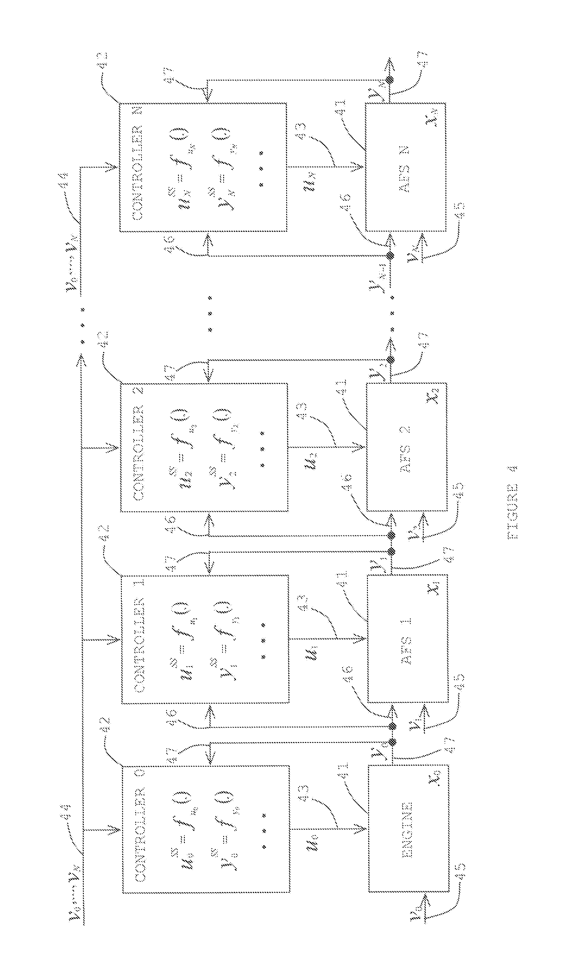
[0007] FIG. 4 is a diagram of the example in FIG. 3 with an engine and a multiple of aftertreatment subsystems; and
[0008] FIG. 5 is a diagram of an illustrative example of an approach for the engine and aftertreatment system.
DESCRIPTION
[0009] The modern combustion engine appears to be a very complex system. The complexity growth may be driven namely by governmental legislation that restricts combustion engine emissions. Therefore, the original equipment manufacturers (OEMs) may be forced to add various equipment items, sensors and actuators to the engine to achieve the prescribed limits and to optimize engine operating costs, e.g., fuel economy, urea consumption, and so forth. Under these conditions, an engine operation optimization and design of an optimal control system may be a challenging task.
[0010] Some approaches may incorporate optimizing the engine and individual aftertreatment systems involving, e.g., selective catalytic reduction (SCR), diesel oxidation catalysts (DOC), diesel particulate filter (DPF), and so on, separately. These approaches do not necessarily provide a systematic way of optimization. They may involve time consuming and expensive tasks. Furthermore, it is not necessarily ensured that their results will be optimal. There might be a better solution.
[0011] Another approach may be to optimize the engine together with the aftertreatment subsystem (AFS) as a one system. Such an approach may enable one to find the global optimal behavior of the engine with an aftertreatment subsystem from an economical and technical point of view while satisfying virtually all of the prescribed emission limits. The engine and aftertreatment subsystem may have appropriate sensors and actuators as needed to effect an optimization program for the engine and aftertreatment subsystem or subsystems as one system. The engine may be seen as an exhaust gas source for the aftertreatment subsystem. The properties of the engine out exhaust gas as sensed may be influenced within certain range by manipulating available engine actuators such as those of a turbocharger waste gate (WG), variable geometry turbocharger (VGT), exhaust gas recirculation (EGR), start of injection (SOI), throttling valve (TV), and so on. Various degrees of freedom may be used to prepare or modify the exhaust gas properties for optimal operation of the aftertreatment subsystem at virtually all of the engine operating points. For example, if the actual state of the aftertreatment subsystem does not enable a reduction of emissions due to low temperature as sensed in some operating regimes, then the engine actuators may be controlled to increase temperature so that the engine exhaust gas out emissions do not violate prescribed limits. On the other hand, if the state of the aftertreatment subsystem enables a reduction of a significant amount of pollutants, the engine actuators may be controlled in a way to also achieve the best fuel economy.
[0012] An engine optimization and control design may be formulated as a rigorous mathematical optimization problem. The present approach may offer a modular and systematic solution to the problem. The approach may incorporate dividing the engine and aftertreatment optimization and control design into two stages: (i) an off-line part and (ii) an on-line part (real-time).
[0013] (i) The off-line part may be formulated as a mathematical optimization problem with constraints (known as mathematical programming) and the results may be various engine maps prescribing setpoints and constraints for different kinds of measured variables from sensors and positions of virtually all engine actuators for virtually all major operating points or conditions of the engine, e.g., over the engine speed and torque map. Virtually all of the maps may be parameterized by various variables of the engine and aftertreatment system but may be also parameterized by measured fuel and/or urea consumption and corresponding costs, by their ratio, or other relevant economically related quantities. Information about actual market prices of fuel and other fluids used by the engine and aftertreatment system may be incorporated to parameterize the control system and may be used as a tuning parameter during the engine's lifetime. This approach may enable a slight tuning of the controller behavior when the prices of the fluids used are changed, which can ensure economically optimal operation of the engine in view of such changes during its lifetime.
[0014] (ii) The on-line part may consist of one or more feedback single or multivariable real-time controllers. These controllers may be implemented, for example, as model based predictive controllers (MPCs). The feedback controllers may ensure realization of virtually all of the setpoints, but also satisfaction of virtually all of the constraints computed in the off-line part. The feedback controllers may also ensure disturbance rejection, a minimization of an impact of engine components production variability, and aging of the engine. Furthermore, the feedback controllers may also be designed to deliver needed performance during an engine transient operation.
[0015] FIG. 1 is a block diagram of a basic scheme of the present system for integrated optimization and control of an engine with one or more aftertreatment systems. The various blocks represent an engine 11, and several aftertreatment systems (AFSs) 12 and 13. Aftertreatment system 13 may be the last system and be denoted by an "N". "N" may also indicate the total number of aftertreatment systems. An aftertreatment system 12 between engine 11 and aftertreatment system N may be denoted by an "i". There may be any number of aftertreatment systems. If there is one aftertreatment system, then it may be represented as system N, wherein N=1.
[0016] "x.sub.0" within the symbol for engine 11 may indicate an internal state of the engine. "x.sub.i" and "x.sub.N" may indicate internal states of AFSi 12 and AFSN 13, respectively. "v.sub.0" may represent an external input 15 to engine 11. The external input may incorporate disturbance, fluid price, and so on. Similarly, "v.sub.i" and "v.sub.N" may represent external inputs 24 and 25 for AFSi 12 and AFSN 13, respectively. A .sub.".sub.U0" input 16 may represent an actuator or actuators of engine 11, a "u.sub.i" input 26 may represent an actuator or actuators of AFSi 12, and a "u.sub.N" input 27 may represent an actuator or actuators of AFSN 13. Inputs 16, 26 and 27 may incorporate actuator inputs.
[0017] "J.sub.0(x.sub.0,v.sub.0,u.sub.0)" on an output 17 may represent a subsystem cost function of x.sub.0, v.sub.0 and/or u.sub.0 for engine 11. "g(x.sub.0,v.sub.0,u.sub.0).ltoreq.0" also on output 17 may represent subsystem constraints of x.sub.0, v.sub.0 and/or u.sub.0 for engine 11. "y.sub.0" may represent an interconnection output 18 from engine 11 which may be an interconnection input "y.sub.i-1" 19 to AFSi 12, assuming that AFSi 12 is the first AFS connected to engine 11, where i=1. However, there may be one or more AFSs connected between engine 11 and AFSi 12. "y.sub.i" may represent an interconnection output 21 from AFSi 12 which may be an interconnection input "y.sub.N-1" 22 to AFSN 13, assuming that AFSN 13 is connected to AFSi 12. However, there may be one or more AFSs connected between AFSi 12 and AFSN 13. "y.sub.N" may represent an output 23 of the AFSN 13 and the preceding AFSs from "1" through "N-1".
[0018] "J.sub.i(x.sub.i,v.sub.i,u.sub.i,y.sub.i-1)" on an output 28 may represent a subsystem cost function of x.sub.i, v.sub.i, u.sub.i and/or y.sub.i-1 for AFSi 12. "J.sub.i(.)" may be an abbreviated designation of the subsystem cost function. "g(x.sub.i,v.sub.i,u.sub.i,y.sub.i-1).ltoreq.0" also on output 28 may represent subsystem constraints of x.sub.i, v.sub.i, u.sub.i and/or y.sub.i-1 for AFSi 12. "g(.)" may be an abbreviated designation of the subsystem constraints. "J.sub.N(x.sub.N,v.sub.N,u.sub.N,y.sub.N-1" on an output 29 may represent subsystem cost function of x.sub.N, v.sub.N, u.sub.N and/or y.sub.N-1 for AFSN 13. "g(x.sub.N,v.sub.N,u.sub.N,y.sub.N-1).ltoreq.0" also on output 29 may represent subsystem constraints of x.sub.N, v.sub.N, u.sub.N and/or y.sub.N-1 for AFSN 13. The similar designations may be made for additional AFSs, if any, between engine 11 and AFSi 12 and between AFSi 12 and AFSN 13, as done herein with the xs, vs, us and ys.
[0019] FIG. 2 may aid in illustrating off-line optimization. An objective may be to compute optimal steady-state engine maps for virtually all of the operating points, for example, in an engine speed-torque space as shown with a graph 31 of engine torque (nm) versus engine speed (rpm). Graph 31 illustrates an example k-th operating point 32 plotted at a specific torque and engine speed. The k-th operating point may represent any point at various locations on graph 31.
[0020] An optimization problem in each operating point may be indicated by:
min U J = i = 0 N J i ( x i , v i , u i , y i - 1 ) ; U = { u 0 , u 1 , , u N } ##EQU00001## s . t . g ( x i , v i , u i , y i - 1 ) .ltoreq. 0 ; i = 0 , 1 , , N . ##EQU00001.2##
The resulting optimal steady-state maps may be indicated by:
u.sub.i.sup.SS=f.sub.u.sub.i(v.sub.0, . . . , v.sub.N) and
y.sub.i.sup.SS=f.sub.y.sub.i(v.sub.0, . . . , v.sub.N),
Abbreviated designations of the steady-state map indications may be u.sub.i.sup.SS=f.sub.u.sub.i(.) and y.sub.i.sup.SS=f.sub.y.sub.i(.), respectively. It may be noted that the maps may also be parameterized by x.sub.i under certain conditions.
[0021] An on-line part (real-time) for an i-th aftertreatment subsystem or an engine may be illustrated in FIG. 3. A controller may be integrated with an engine and an AFS. An engine or AFS_i 41 may have an internal state of x.sub.0 or x.sub.i, respectively. An actuator input u.sub.0 or u.sub.i 43 may go to the engine or AFS_i 41, respectively. The actuator input 43 may come from a controller_0 or a controller_i 42, respectively. Controller 42 may provide steady state maps as represented by symbols u.sub.0.sup.SS=f.sub.u.sub.0(.) and y.sub.0.sup.SS=f.sub.y.sub.0(.) or u.sub.i.sup.SS=f.sub.u.sub.i(.) and y.sub.i.sup.SS=f.sub.y.sub.i(.), respectively. The controller_i 42 may be implemented by MPC controller. External inputs v.sub.0, . . . , v.sub.N (i.e., disturbance, fluid price, and so forth) may be provided to controller 42. A specific input v.sub.0 or v.sub.i 45 may be input to engine or AFS_i 41, respectively. An interconnection output y.sub.i-1 47 from an engine or an AFS_i-1 may be an input 46 to AFS_i 41 and controller_i 42. There may be an interconnection output y.sub.0 or y.sub.i 47 from the engine or AFS_i 41 as an input 46 for an AFS_i+1 or an AFS_N. Interconnection output 47 may also go to controller_i 42. In general, 47 may contain also signals which are not interconnections but measurements of variables that can be useful for integrated optimization.
[0022] The on-line part for an i-th subsystem of FIG. 3 may be illustrated as an engine and multiple AFSs connected in a diagram of FIG. 4. Two or more controllers 42 of FIG. 4 may be combined as one controller 42. The numerical labels are the same for similar components and lines as shown in FIG. 3.
[0023] FIG. 5 is diagram of a two-part engine and aftertreatment optimization control approach 50 with an off-line stage 51 and an on-line stage 52. At the off-line stage 51 may be a mathematical optimization of the engine and aftertreatment system at symbol 53, an engine map with setpoints and constraints at symbol 54, and a parameterization of engine maps at symbol 55. At the on-line stage 52 may be feedback real-time controller or controllers at symbol 56, a realization of setpoints at symbol 57, and a satisfaction of constraints at symbol 58.
[0024] Some of the items or activities of the disclosed system in FIGS. 1-5 not covered by one or more controllers may be performed by a processor/computer.
[0025] A recap of the disclosure is provided in the following. An engine and aftertreatment system may incorporate an engine, an aftertreatment mechanism connected to the engine, and a controller connected to the engine and the aftertreatment mechanism. The controller may have an optimization program. The optimization program may be for optimized performance of the engine and the aftertreatment mechanism integrated as one system. Optimized performance may incorporate reducing emissions and increasing fluid efficiency of the one system.
[0026] The optimization program may incorporate the aftertreatment mechanism for reducing emissions from an exhaust of the engine to a prescribed level, and increasing fluid efficiency of the engine and the aftertreatment mechanism while the emissions are reduced at least down to the prescribed level.
[0027] The engine may incorporate a control input to actuators on the engine, an interconnection output and an information output. The information output may indicate engine costs and/or engine constraints. The aftertreatment mechanism may incorporate an interconnection input connected to the interconnection output of the engine, a control input to actuators on the aftertreatment mechanism, an interconnection output, and an information output. The information output may indicate aftertreatment mechanism costs and/or aftertreatment mechanism constraints. The costs and constraints may be a basis incorporated in the optimization program for optimized performance of the engine and the aftertreatment mechanism integrated as one system.
[0028] The controller may further incorporate a first input connected to the interconnection output of the engine, a first output connected to the control input to actuators of the engine, a second input connected with the interconnection input of the aftertreatment mechanism, a third input connected to the interconnection output of the aftertreatment mechanism, and a second output connected to the control input to actuators of the aftertreatment mechanism.
[0029] The controller may further incorporate a feedback loop for disturbance rejection, minimizing an impact of variability of performance of the engine, and/or delivering predetermined performance of the aftertreatment mechanism during transient operation of the engine, and maps prescribing setpoints and constraints for measured variables and positions of engine actuators for one or more operating points of the engine. The maps may be parameterized by variables of the engine and the aftertreatment mechanism. The maps may be a basis incorporated in the optimization program for optimized performance of the engine and the aftertreatment mechanism integrated as one system.
[0030] An approach for engine and aftertreatment optimization and control may incorporate formulating an off-line part which involves mathematically optimizing an engine and aftertreatment system, providing engine maps prescribing setpoints and constraints for measured variables from sensors and positions of engine actuators for operating points and conditions of the engine, and parameterizing the engine maps with variables of the engine and the aftertreatment system.
[0031] The approach for engine and aftertreatment optimization and control may also incorporate formulating an on-line part providing one or more feedback real-time controllers realizing the setpoints of the engine and aftertreatment system, and satisfying computed constraints with the one or more controllers. The one or more controllers may be model predictive controllers.
[0032] The one or more controllers may ensure disturbance rejection, minimization of input of engine components production variability, and/or engine aging. The one or more controllers may deliver needed performance during an engine transient operation.
[0033] The approach may further incorporate parameterizing the engine and aftertreatment system by measured fuel, urea consumption and/or corresponding costs. The approach may also further incorporate parameterizing a control system with market price information of fuel and other fluids used by the engine and aftertreatment system. There may also be parameterizing the control system to tune the controller when there are changes of prices of fluids used by the engine and aftertreatment system to ensure economically optimal operation of the engine during the changes.
[0034] There may be a system of an engine and aftertreatment subsystem incorporating an engine, an aftertreatment subsystem connected to the engine, and a controller connected to the engine and the aftertreatment subsystem. The controller may receive signals from sensors of the engine and the aftertreatment subsystem, process the signals, and provide signals to actuators of the engine and the aftertreatment subsystem according to an optimization program for optimized performance of the engine and the aftertreatment subsystem as one system. The optimized performance may incorporate reducing emissions and increasing fluid efficiency of the one system.
[0035] The external inputs of the engine and the aftertreatment subsystem may be connected to the controller. The controller may incorporate engine maps for operating points of the engine. The maps may be a basis for optimized performance of the engine and the aftertreatment subsystem as one system. The maps may prescribe setpoints and constraints for measured variables from the sensors and for actuators.
[0036] The engine may incorporate an external input and an actuator input from the controller, and an interconnection output connected to the controller. The external input may have external information pertinent to the engine.
[0037] The aftertreatment subsystem may incorporate an interconnection input connected to the interconnection output of the engine and connected to the controller, an external input, an actuator input from the controller, and an interconnection output connected to the controller. The external input may have external information pertinent to the aftertreatment subsystem.
[0038] The engine may further incorporate an internal state and an information output. The information output may indicate engine costs as a function of the engine internal state, the external input and/or the actuator input.
[0039] The aftertreatment subsystem may further incorporate an internal state and an information output. The information output may indicate aftertreatment costs as a function of the aftertreatment subsystem internal state, the external input, actuator input, and/or the interconnection input.
[0040] The information output of the engine may indicate engine constraints as a function of the internal state, the external input and/or the actuator input of the engine. The information output of the aftertreatment subsystem may indicate aftertreatment constraints as a function of the internal state, the external input, the actuator input, and/or the interconnection input of the aftertreatment subsystem. The costs and constraints may be a basis for optimized performance of the engine and the aftertreatment subsystem as one system.
[0041] An approach for controlling a combined engine and aftertreatment system may incorporate providing an engine, adding one or more aftertreatment subsystems to result in a combined engine and aftertreatment system, connecting one of the one or more aftertreatment subsystems to an exhaust output of the engine, and manipulating actuators of the engine and the one or more aftertreatment subsystems with one or more controllers to change the properties of the exhaust for optimal operation of the combined engine and aftertreatment system. Optimal operation may incorporate reduction of emissions and improvement of fluid efficiency of the combined engine and aftertreatment system.
[0042] To change the properties of the exhaust may incorporate reducing an amount of pollutants in the exhaust to a magnitude equal to or less than a prescribed magnitude. Manipulating the actuators of the engine may increase fuel economy of the engine if the one or more aftertreatment subsystems reduce an amount of pollutants in the exhaust to a magnitude equal to or less than the prescribed magnitude.
[0043] The approach may further incorporate providing one or more engine maps as a basis for optimal operation of the combined engine and aftertreatment system, processing the one or more engine maps prescribing setpoints and/or constraints for measured variables and positions of the actuators on the engine for operating points and/or conditions of the engine, and parameterizing the engine maps by variables of the engine and of the one or more aftertreatment subsystems.
[0044] The approach may further incorporate parameterizing the engine maps by costs of fuel consumed by the engine and/or urea consumed by the one or more aftertreatment subsystems. The one or more engine maps may incorporate a speed and torque map of the engine. The one or more controllers may be connected to the engine and the one or more aftertreatment subsystems of the combined engine and aftertreatment system. The one or more controllers may ensure realization of the setpoints, and/or ensure satisfaction of the constraints.
[0045] In the present specification, some of the matter may be of a hypothetical or prophetic nature although stated in another manner or tense.
[0046] Although the present system and/or approach has been described with respect to at least one illustrative example, many variations and modifications will become apparent to those skilled in the art upon reading the specification. It is therefore the intention that the appended claims be interpreted as broadly as possible in view of the related art to include all such variations and modifications.
* * * * *
uspto.report is an independent third-party trademark research tool that is not affiliated, endorsed, or sponsored by the United States Patent and Trademark Office (USPTO) or any other governmental organization. The information provided by uspto.report is based on publicly available data at the time of writing and is intended for informational purposes only.
While we strive to provide accurate and up-to-date information, we do not guarantee the accuracy, completeness, reliability, or suitability of the information displayed on this site. The use of this site is at your own risk. Any reliance you place on such information is therefore strictly at your own risk.
All official trademark data, including owner information, should be verified by visiting the official USPTO website at www.uspto.gov. This site is not intended to replace professional legal advice and should not be used as a substitute for consulting with a legal professional who is knowledgeable about trademark law.