Adjustable Coupler For Awning Having Articulating Support Arm
Smoot; Stevan ; et al.
U.S. patent application number 16/296838 was filed with the patent office on 2019-09-12 for adjustable coupler for awning having articulating support arm. The applicant listed for this patent is Lippert Components, Inc.. Invention is credited to Samual Evans, Michael J. Fiwek, Stevan Smoot, Evan Whitney, Brian M. Worthman.
| Application Number | 20190277035 16/296838 |
| Document ID | / |
| Family ID | 67842399 |
| Filed Date | 2019-09-12 |


| United States Patent Application | 20190277035 |
| Kind Code | A1 |
| Smoot; Stevan ; et al. | September 12, 2019 |
ADJUSTABLE COUPLER FOR AWNING HAVING ARTICULATING SUPPORT ARM
Abstract
An articulating coupler includes first and second pivot members that may be pivoted with respect to each other. A locking member and a locking lever are configured to selectively lock the first pivot member to the second pivot member in a plurality of relative positions. The locking member is configured to float over a pivot range in a first direction with the locking lever in a lock position.
| Inventors: | Smoot; Stevan; (Alpine, CA) ; Worthman; Brian M.; (Goshen, IN) ; Fiwek; Michael J.; (Plymouth, IN) ; Evans; Samual; (Granger, IN) ; Whitney; Evan; (Edwardsburg, MI) | ||||||||||
| Applicant: |
|
||||||||||
|---|---|---|---|---|---|---|---|---|---|---|---|
| Family ID: | 67842399 | ||||||||||
| Appl. No.: | 16/296838 | ||||||||||
| Filed: | March 8, 2019 |
Related U.S. Patent Documents
| Application Number | Filing Date | Patent Number | ||
|---|---|---|---|---|
| 62640111 | Mar 8, 2018 | |||
| Current U.S. Class: | 1/1 |
| Current CPC Class: | E04F 10/0629 20130101; E04F 10/0614 20130101; E04F 10/0651 20130101 |
| International Class: | E04F 10/06 20060101 E04F010/06 |
Claims
1. An adjustable coupler comprising: a first pivot member including a first shank configured to engage a first member of a support arm, and including a first hub portion; a second pivot member pivotably associated with the first pivot member, the second pivot member including a second shank configured to engage a second member of the support arm, and including a fork; a locking member pivotably associated with the first pivot member and the second pivot member, the locking member received by the first hub portion and the fork in pivotable engagement; a locking lever pivotably engaged with the second pivot member, the locking lever configured for selective locking engagement with the locking member; and a cover comprising a second hub portion, the second hub portion configured for pivotable engagement with the first pivot member, wherein the locking lever is configured to selectively lock the locking member to the second pivot member in any of a plurality of predetermined orientations, and wherein the locking member, when selectively locked to the second pivot member, is rotatable within a predetermined range with respect to the first pivot member.
2. An adjustable coupler according to claim 1, wherein the first hub portion comprises a first key feature, and wherein the second hub portion comprises a second key feature in complement with the first key feature.
3. An adjustable coupler according to claim 1, wherein the second pivot member is sandwiched between the first pivot member and the cover.
4. An adjustable coupler according to claim 1, wherein the locking member comprises a bore therethrough, and wherein the fork of the second pivot member comprises an aperture therethrough, the locking member being positioned in the fork with the bore in alignment with the aperture.
5. An adjustable coupler according to claim 4, further comprising a bushing having an opening therein disposed in the bore and the aperture.
6. An adjustable coupler according to claim 5, wherein the first hub portion of the first pivot member is disposed in the opening in the bushing, and wherein the second hub portion of the cover is disposed in the opening, the first hub portion engaging the second hub portion through the bushing.
7. An adjustable coupler according to claim 6, further comprising a connector extending through the cover and the second hub portion, through the bushing, and into the first hub portion.
8. An adjustable coupler according to claim 1, wherein the locking lever is displaceable between a lock position in which the locking lever engages the locking member and a release position in which the locking lever is disengaged from the locking member.
9. An adjustable coupler according to claim 8, further comprising a lever biasing member disposed between the locking lever and the second pivot member, the lever biasing member biasing the locking lever toward the lock position.
10. An adjustable coupler according to claim 1, further comprising a unit biasing member connected between the locking member and the first pivot member, the unit biasing member biasing the locking member toward the first pivot member.
11. An adjustable coupler according to claim 10, wherein the predetermined range is defined by an extended length of the unit biasing member.
12. An adjustable coupler comprising: a first pivot member including a first hub portion; a second pivot member pivotably associated with the first pivot member, the second pivot member including a fork; a locking member pivotably associated with the first pivot member and the second pivot member, the locking member received by the first hub portion and the fork in pivotable engagement; a locking lever pivotably engaged with the second pivot member; and a cover comprising a second hub portion, the second hub portion configured for pivotable engagement with the first pivot member, wherein the locking lever is displaceable between a lock position in which the locking lever engages the locking member and a release position in which the locking lever is disengaged from the locking member, wherein with the locking lever in the release position, the first pivot member is freely pivotable relative to the second pivot member, and wherein with the locking lever in the lock position, the locking member and the second pivot member are rotatable within a predetermined range with respect to the first pivot member.
13. An adjustable coupler according to claim 12, further comprising a lever biasing member disposed between the locking lever and the second pivot member, the lever biasing member biasing the locking lever toward the lock position.
14. An adjustable coupler according to claim 12, further comprising a unit biasing member connected between the locking member and the first pivot member, the unit biasing member biasing the locking member toward the first pivot member.
15. An adjustable coupler according to claim 14, wherein the predetermined range is defined by an extended length of the unit biasing member.
Description
CROSS-REFERENCES TO RELATED APPLICATIONS
[0001] This application claims the benefit of U.S. Provisional Patent Application No. 62/640,111, filed Mar. 8, 2018, the entire content of which is herein incorporated by reference.
STATEMENT REGARDING FEDERALLY SPONSORED RESEARCH OR DEVELOPMENT
[0002] (NOT APPLICABLE)
BACKGROUND AND SUMMARY
[0003] This disclosure relates to retractable awnings and, more particularly, to retractable awnings having one or more articulated support arms configured to allow varying the pitch of the awning fabric, for example, to facilitate dumping accumulated water from the awning fabric.
[0004] Such awnings may be used, for example, on recreational vehicles. Examples of such awnings include, without limitation, those disclosed in U.S. Pat. No. 8,752,606 ("the '606 patent") and U.S. Pat. No. 9,410,326 ("the '326 patent"), the disclosures of which are incorporated herein by reference in their entireties. The '606 patent and the '326 patent are commonly owned by the current assignee.
[0005] In awnings having one or more articulated support arms, the articulated support arm(s) may include first and second arm elements that are adjustable relative to one another and are joined by an adjustable coupler. The adjustable coupler may simply comprise a nut and bolt. The nut and bolt may be adjusted to apply a predetermined force to the interface between the first and second arm elements, thereby establishing sufficient friction therebetween to maintain the first and second arm elements in a particular orientation relative to each other when a torque applied thereto is less than a predetermined amount, while allowing a user to manually articulate the first arm element with respect to the second arm element when a torque applied thereto is greater than a predetermined amount. This structure, however, is not configured to return the original orientation when the greater torque is removed.
[0006] It would be desirable to provide an adjustment coupler with a biasing mechanism, for example, a Belleville washer or compression spring, in combination with the nut and bolt such that the Belleville washer may apply a load to the joint. The adjustment coupler may accommodate selective positioning of the first and second arm elements and may also accommodate a torque that deflects one arm element relative to the other, while returning to the configuration when the torque is removed. The adjustment coupler may incorporate a mechanism that is able to selectively lock the first and second arm elements into any of several orientations with respect to each other.
[0007] In an exemplary embodiment, an adjustable coupler includes a first pivot member with a first shank configured to engage a first member of a support arm, and with a first hub portion, and a second pivot member pivotably associated with the first pivot member and including a second shank configured to engage a second member of the support arm and a fork. A locking member pivotably associated with the first pivot member and the second pivot member is received by the first hub portion and the fork in pivotable engagement. A locking lever pivotably engaged with the second pivot member is configured for selective locking engagement with the locking member. A cover includes a second hub portion that is configured for pivotable engagement with the first pivot member. The locking lever is configured to selectively lock the locking member to the second pivot member in any of a plurality of predetermined orientations. The locking member, when selectively locked to the second pivot member, is rotatable within a predetermined range with respect to the first pivot member.
[0008] The first hub portion may include a first key feature, and the second hub portion may include a second key feature in complement with the first key feature. The second pivot member may be sandwiched between the first pivot member and the cover.
[0009] The locking member may include a bore therethrough, and the fork of the second pivot member may include an aperture therethrough. In this context, the locking member may be positioned in the fork with the bore in alignment with the aperture. The coupler may also include a bushing having an opening therein disposed in the bore and the aperture. The first hub portion of the first pivot member may be disposed in the opening in the bushing, and the second hub portion of the cover may be disposed in the opening, where the first hub portion may engage the second hub portion through the bushing. The coupler may also include a connector extending through the cover and the second hub portion, through the bushing, and into the first hub portion.
[0010] The locking lever may be displaceable between a lock position in which the locking lever engages the locking member and a release position in which the locking lever may be disengaged from the locking member. A lever biasing member may be disposed between the locking lever and the second pivot member that biases the locking lever toward the lock position.
[0011] The coupler may also include a unit biasing member connected between the locking member and the first pivot member, where the unit biasing member biases the locking member toward the first pivot member. In this context, the predetermined range may be defined by an extended length of the unit biasing member.
BRIEF DESCRIPTION OF THE DRAWINGS
[0012] These and other aspects and advantages will be described in detail with reference to the accompanying drawings, in which:
[0013] FIG. 1 is a perspective view of an awning support arm mechanism including an articulating support arm and an adjustable coupler pivotably connecting first and second members of the articulating support arm, with the articulating support arm in an un-articulated configuration;
[0014] FIG. 2 is a perspective view of the awning support arm mechanism of FIG. 1 with the articulating support arm in an articulated configuration;
[0015] FIG. 3 is an exploded perspective view of the adjustable coupler of the awning support arm mechanism of FIG. 1;
[0016] FIG. 4A is a cross-sectional side elevation view of a portion of the awning support arm mechanism of FIG. 1;
[0017] FIG. 4B is a cross-sectional perspective view of a portion of the awning support arm mechanism of FIG. 1;
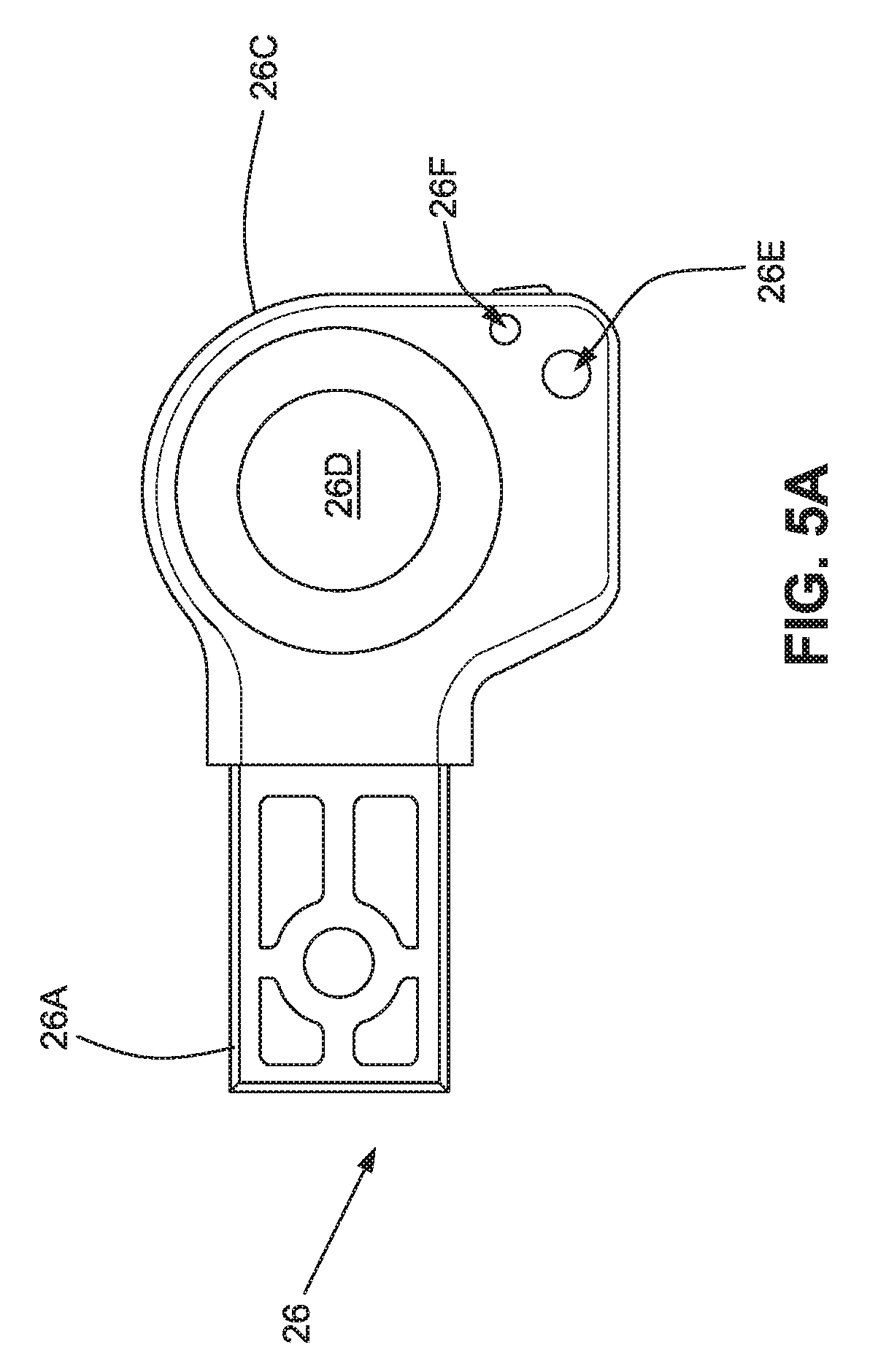
[0018] FIG. 5A is a side elevation view of a portion of the awning support arm mechanism of FIG. 1;
[0019] FIG. 5B is a side elevation view of a portion of the awning support arm mechanism of FIG. 1;
[0020] FIG. 6A is a cut-away perspective view of a portion of the awning support arm mechanism of FIG. 1;
[0021] FIG. 6B is a cross-sectional top plan view of a portion of the awning support arm mechanism of FIG. 1; and
[0022] FIG. 7 a cut-away perspective view of the awning support arm mechanism of FIG. 1.
DETAILED DESCRIPTION
[0023] FIGS. 1 and 2 show an awning support mechanism 10 configured to support a first end of an awning roller R and to extend and retract the awning roller away from and toward a structure, for example, a recreational vehicle (RV) to which the awning support mechanism may be attached.
[0024] The mechanism 10 includes an elongated base 12, a first (or upper) elongated support arm 14, a second (or lower) elongated support arm 16, a third (or outboard) elongated support arm 18, and an elongated biasing member 20, each having a first end and a second end. The biasing member 20 may be, for example, a gas strut.
[0025] As shown, the first support arm 14 may be embodied as an elongated channel defining an interior space configured to selectively receive at least portions of the second support arm 16 and the biasing member 20. Similarly, the base 12 may be embodied as an elongated channel defining an interior space configured to selectively receive at least portions of the first support arm 14, the second support arm 16 and the biasing member 20. The third support arm 18 may be embodied as an elongated channel defining an interior space configured to selectively receive at least portions of the base 12, the first support arm 14, the second support arm 16 and the biasing member 20.
[0026] The base 12 is configured for attachment to a wall of the structure in a generally vertical orientation, with the first end of the base above the second end of the base and the base generally parallel to the wall of the structure. The first end of the first support arm 14 is pivotably connected to the base 12 at a first pivot point P1. As shown, the first pivot point P1 is relatively near the first end of the base 12. The first end of the second support arm 16 is pivotably connected to the base 12 at a second pivot point P2 intermediate the first pivot point P1 and the second end of the base. As shown, the second pivot point P2 is at or near the midpoint of the base 12. The second end of the second support arm 16 is pivotably connected to the third support arm 18 at a third pivot point P3. As shown, the third pivot point P3 is relatively near the second end of the third support arm 18. The second end of the first support arm 14 is connected to the third support arm 18 at a fourth pivot point P4 intermediate the third pivot point P3 and the first end of the third support arm 18. As shown, the fourth pivot point P4 is substantially nearer the second end of the third support arm 18 than it is to the first end of the third support arm. The first end of the biasing member 20 is pivotably connected to the first support arm 14 at a fifth pivot point P5 intermediate the first pivot point P1 and the fourth pivot point P4. As shown, the fifth pivot point P5 is proximate the first pivot point P1. The second end of the biasing member 20 is pivotably connected to the second pivot arm 16 at a sixth pivot point P6 intermediate the second pivot point P2 and the third pivot point P3. As shown, the sixth pivot point P6 is proximate the second pivot point P2.
[0027] The second support arm 16 includes an elongated first member 16A and an elongated second member 16B, each having a first end and a second end. The first end of the first member 16A corresponds to the first end of the second support arm 16, and the second end of the second member 16B corresponds to the second end of the second support arm 16. The second end of the first member 16A is connected to the first end of the second member 16B by an intervening adjustable coupler 22.
[0028] With reference to FIGS. 3-7, the coupler 22 includes a first pivot member 24, a second pivot member 26, a locking member 28, a bushing 30, a locking lever 32, and a retainer/cover 34.
[0029] The first pivot member 24 includes a first shank 24A and a flange 24B connected to the first shank. The first shank 24A is configured for attachment to the first member 16A of the second support arm 16. As shown, the first member 16A of the second support arm 16 is embodied as a square tube defining a first interior having first inside dimensions, and the shank 24A defines a first exterior having first outside dimensions complementary to the first inside dimensions so that the first shank may be received within the interior space defined by the first member 16A as a press-fit or otherwise. The flange 24B extends in a direction generally parallel to and opposite the first shank 24A.
[0030] A hub 24C extends from the flange 24B, generally perpendicular thereto. The hub 24C defines a hub outer circumferential surface and a hub outer diameter. The hub 24C also defines a hub aperture 24D extending axially into a central portion thereof from a free end thereof. A free end of the hub 24B may define a key feature 24K. As shown, the key feature 24K is an extension of the hub 24B, the key feature having a square outer profile.
[0031] The first pivot member 24 also defines a limit stop 24E, which may be embodied as a shelf, configured to limit the rotation of the locking member, as will be discussed further below.
[0032] The first pivot member 24 further defines a trough 24F configured to receive at least a portion of and anchor an end of a biasing spring, as will be discussed further below. As shown, the limit stop 24E and the trough 24F are intermediate the shank 24A and the hub 24C. The first pivot member 24 also defines a spring fastener-receiving aperture 24G (not visible in FIG. 3; see FIGS. 4A and 4B) extending inwardly toward the shank 24A from a surface of the trough 24F. Moreover, the first pivot member 24 defines a cover fastener-receiving aperture 24H configured to receive a screw or other fastener in thread engagement, as will be discussed further below.
[0033] The second pivot member 26 includes a second shank 26A and a fork 26B connected to the second shank. The second shank 26A is configured for attachment to the second member 16B of the second support arm 16. As shown, the second member 16B of the second support arm 16 is embodied as a square tube defining a second interior having second inside dimensions, and the second shank 26A defines a second exterior having second outside dimensions complementary to the first inside dimensions so that the second shank may be received within the interior space defined by the second member 16B as a press-fit or otherwise. The fork 26B extends in a direction generally parallel to and opposite the second shank 26A. The fork 26B may be embodied as a pair of blades 26C, each of the blades 26C defining a corresponding bushing-receiving aperture 26D therethrough and a corresponding interior surface 26C-1 facing the other of the pair of blades 26C. The respective interior surfaces of the pair of blades 26C are substantially parallel to each other and spaced apart from each other by a first predetermined distance. Also, the respective apertures 26D defined by the pair of blades 26C are co-axial with each other.
[0034] Each of the blades 26C also defines a first pin-receiving aperture 26E configured to receive a first pin, as will be discussed further below. At least one of the first pin-receiving apertures 26E extends through the corresponding blade 26C. The other of the first pin-receiving apertures 26E may, but need not, extend through the corresponding blade 26C.
[0035] Each of the blades 26C further defines a second pin-receiving aperture 26F configured to receive a second pin, as will be discussed further below. At least one of the second pin-receiving apertures 26F extends through the corresponding blade 26C. The other of the second pin-receiving apertures 26F may, but need not, extend through the corresponding blade 26C.
[0036] As shown, the locking member 28 is embodied as a ring defining an aperture or bore 28A therethrough, a pair of opposed lateral surfaces, and an outer circumferential surface, the outer circumferential surface defining a plurality of protrusions 28B in the form of gear teeth and a plurality of valleys 28C. A flange 28D extends tangentially from the circumferential outer surface of the locking member 28. The thickness of the locking member 28 is complementary to the first predetermined distance separating the first and second blades 26C of the fork 26B so that the locking member 28 may be received between the pair of blades 26C in rotating engagement with respect thereto, as will be discussed further below. The locking member 28 also defines a circumferentially-oriented, arcuate slot 28E extending axially therethrough. As shown, the slot 28E extends over about one-quarter of the circumference of the locking member 28. In other embodiments, the circumferential extent of the slot 28E may be selected as desired. The locking member 28 further defines a screw-receiving aperture 28F extending radially inwardly from the outer surface thereof.
[0037] The bushing 30 is in the form of an annular tube defining an aperture 30A therethrough and having an inner diameter and an outer diameter. The inner diameter of the bushing 30 is complementary to the outer diameter of the hub 24C so that the hub 24C may be received within the aperture 30A of the busing 30 in rotating engagement. Also, the outer diameter of the bushing 30 is complementary to the inner diameter of the apertures defined by the blades 26C of the fork 26B and the inner diameter of the aperture 28A defined by the locking member 28 so that the bushing may be received within the foregoing apertures 26C, 28A in rotating engagement.
[0038] The cover 34 includes a flange 34A having a first (or inner) surface and a second (or outer) surface, and a hub 34B extending perpendicularly from the inner surface. The hub 34B defines an outer circumferential surface complementary to the outer circumferential surface of the hub 24C of the first pivot member 24. As best shown in FIGS. 6A and 6B, the hub 34B may define a key feature 34K complementary to the key feature 24K of the first pivot member 24. As shown, the key feature 34K is a cavity extending axially inwardly from a free end of the hub 34B and having a square cross section complementary to the square cross section of the key feature 24D of the first pivot member 24. The cover 34 also defines first and second fastener-receiving apertures 34C, 34D.
[0039] The lever 32 has a first end, a second end, and a lever pivot axis between the first end and the second end. As shown, the lever pivot axis is defined by one or more pin-receiving lever apertures 32A extending through the lever 32. The first end of the lever 32 defines a surface 32B configured for actuation by a user. The surface 32B (or other portion of the first end of the lever 32) may also be configured for actuation by the base 12 or another structure, as will be discussed further below. The second end of the lever 32 defines a locking tab 32C. The locking tab 32C is complementary to, and configured to engage with, the valleys 28C defined by the locking ring 28.
[0040] A lever biasing member 38 may be provided to pivotably bias the lever 32, as will be discussed further below. As shown, the lever biasing member 38 may be embodied as a torsion spring having a spring coil 38A defining an aperture and first and second legs 38B, 38C extending from the spring coil.
[0041] The lever 32 may be assembled to the second pivot member 26 by coaxially aligning the pin-receiving lever aperture(s) 32A defined by the lever with the first pin-receiving apertures 26E defined by the blades 26C of the second pivot member 26 and with the aperture defined by the spring coil 38A of the biasing member. With the foregoing apertures 32A, 26E so aligned, a first pin 36 may be inserted therethrough, thereby securing the lever 32 to the blades 26C of the second pivot member 26 in pivoting engagement. The biasing member 38 may be oriented so that the first leg 38B bears against the lever 32 and the second leg 32C bears against the second pivot member 26 in a manner that pivotably biases the lever in a first, predetermined direction of rotation, as will be discussed further below.
[0042] As suggested above, the coupler 22 may further be assembled by sliding the locking member 28 between the blades 26C of the fork 26B of the second pivot member so that the aperture 28A defined by the locking member 28 is coaxial with the apertures 26D defined by the pair of blades 26C and so that the slot 28E defined by the locking member is aligned with the second pin-receiving apertures 26F defined by the pair of blades 26C. With the locking member 28 so received between the blades 26C, a second pin 40 may be received within the first pin-receiving apertures 26E defined by the pair of blades 26C and the slot defined 28E by the locking member. Also, the bushing 30 may be received within the aperture 28A defined by the locking member 28 and the bushing apertures 26D defined by the pair of blades 26C. Further, the hub 24C may be received within the aperture 30A defined by the bushing 30. The locking member 28 may be oriented so that the flange 28D thereof may engage with the limit stop 24E defined by the first pivot member 24.
[0043] A locking member biasing member 42, for example, a coil tension spring, is connected between the first pivot member 24 and the locking member 28. As shown, a first end of the locking member biasing member 42 is connected to the first pivot member 24 by a first locking member biasing member fastener 44, for example, a screw, extending through the first end of the spring and threaded into the spring fastener-receiving aperture 28F defined by the locking member 28. A second end of the locking member biasing member 42 is connected to the first pivot member 24 by a second locking member biasing member fastener 46 extending through the second end of the spring and threaded into the spring fastener-receiving aperture 24G defined by the first pivot member 24. The locking member biasing member 42 serves to pivotably bias the locking member 28 with respect to the first pivot member 24 and the second pivot member 26 in a first direction of rotation (opposite to arrow A in FIG. 7), thereby biasing the flange 28D of the locking member 28 against the limit stop 24E of the first pivot member 24.
[0044] The cover 34 may be installed to the foregoing subassembly. More specifically, the bushing 30 may receive the hub 34B of the cover 34 in rotating engagement, and the key feature 34K of the cover may receive the key feature 24K of the first pivot member 24 in keyed engagement. A first screw 48 or other fastener may be inserted through the first fastener-receiving aperture 34C of the cover and threaded into the hub aperture 24D of the first pivot member. A second screw 50 or other fastener may be inserted through the second fastener-receiving aperture 34D of the cover and threaded into the fastener-receiving aperture 24H of the first pivot member 24.
[0045] Decals or other covers 52 may be provided to cover any or all of the apertures extending through the cover 34 to conceal the fasteners therein.
[0046] In use, the adjustable coupler 22 may be installed into the second support arm 16. More specifically, the shank 24A of the first pivot member 24 may be inserted into or otherwise connected to the first member 16A of the second support arm 16, and the shank 26A of the second pivot member 26 may be inserted into or otherwise connected to the second member 16B of the second support arm 16.
[0047] The adjustable coupler 22 may be operated to select a desired angle of articulation between the first member 16A of the second support arm 16 and the second member 16B of the second support arm. More specifically, the lever 32 may be actuated to release the engagement tab 32C of the lever from the circumferential outer surface of the locking member 28. For example, the surface 32B defined by the first end of the lever 32 (or another portion of the first end of the lever) may be depressed or otherwise actuated by a user to release the engagement tab 32C of the lever from the circumferential outer surface of the locking member 28. With the engagement tab 32C of the lever 32 released from the circumferential outer surface of the locking member 28, the first pivot member 24A may be freely rotated or pivoted with respect to the second pivot member 24B to a desired angle of articulation. Articulating the support arm 16 as described above may facilitate dumping rain water that might accumulate on the awning to the side of the awning canopy, rather than the free end of the awning canopy opposite the structure S.
[0048] The lever 32 may then be released. With the lever 32 released, the lever biasing member 38 biases the engagement tab 32C of the lever 32 into engagement with the circumferential outer surface 28A of the locking member 28. If the engagement tab 32C is aligned with one of the valleys 28C defined by the locking member 28 when the lever 32 is released, the engagement tab will engage with the valley, thereby locking the engagement tab to the locking member. If the engagement tab 32C is not aligned with one of the valleys 28C defined by the locking member 28 when the lever 32 is released, the first pivot arm 24 may be rotated with respect to the second pivot arm 24 until the engagement tab 32C becomes aligned with one of the valleys 28C defined by the locking member 28, at which time the lever biasing member 38 will cause the engagement tab 32C to become engaged with the foregoing valley 28C, thereby locking the engagement tab to the locking member.
[0049] With the engagement tab 32C of the lever 32 so locked to the locking member 28, pivoting of the first pivot member 24A with respect to the second pivot member 24B in a first direction is precluded due to interaction between the engagement tab and lever with the locking member, and due to interaction between the flange 28D of the locking member with the limit stop 24E defined by the first pivot member. However, the first pivot member 24A may be pivoted with respect to the second pivot member 24B in a second direction (represented by arrow A in FIG. 7) to a limited extent, which limited extent may be defined by the extended length of the locking member biasing member 42 (i.e., the length that the biasing member 42 can be extended without affecting its ability to return to its original orientation).
[0050] The foregoing ability to pivot the first pivot member 24A with respect to the second pivot member 24B in the second direction to a limited extent while the engagement tab 32C of the lever 32 locked to the locking member allows a user to selectively and temporarily decrease the angle of articulation of the first pivot member 24A with respect to the second pivot member 24B and thereby decrease the pitch of an awning roller R connected between a pair of support mechanisms 10 by simply pressing upwardly on the adjustable coupler 22 or on the second support arm 16 proximate the coupler 22. Upon release of the coupler 22 by the user, the locking member biasing member 42 may return the coupler (as well as the awning roller) to its original orientation. It may be desirable to selectively and temporarily decrease the angle of pitch of the awning roller R as discussed above, for example, to temporarily increase the clearance between the ground and the second support arm 16 and/or between the ground and the awning roller R. Also, this arrangement allows external forces, for example, wind forces, to temporarily and selectively pivot the second support arm 16 between an articulated orientation and a non-articulated orientation to mitigate the potential for such external forces to damage the mechanism 10.
[0051] The coupler 22 may be returned from an articulated orientation to a straight, unarticulated orientation (or to a different articulated orientation) by actuating the lever 32 to disengage the engagement tab 32C of the lever from the locking member 28 and reorienting the first pivot member 24A to a desired angle of articulation with respect to the second pivot member 24B.
[0052] In an embodiment, the surface 32B may be actuated by interference between the lever 32 and another structure. For example, the surface 32B may engage with and be actuated by a corresponding surface of the base 12 against or within which the second support arm 16 may be received when the awning support mechanism 10 is transitioned from a deployed position to a retracted position. This feature enables the coupler 22 to automatically revert to a straight orientation (wherein the first shank 24A and the second shank 26A are aligned with each other) from an articulated orientation (wherein the first shank 24A and the second shank 26A are articulated or angled with respect to each other) when the awning support mechanism 10 is transitioned from a deployed configuration to a retracted configuration, thereby precluding damage to the support mechanism.
[0053] While the invention has been described in connection with what is presently considered to be the most practical and preferred embodiments, it is to be understood that the invention is not to be limited to the disclosed embodiments, but on the contrary, is intended to cover various modifications and equivalent arrangements included within the spirit and scope of the appended claims.
* * * * *
D00000
D00001
D00002
D00003
D00004
D00005
D00006
D00007
D00008
D00009
D00010
XML
uspto.report is an independent third-party trademark research tool that is not affiliated, endorsed, or sponsored by the United States Patent and Trademark Office (USPTO) or any other governmental organization. The information provided by uspto.report is based on publicly available data at the time of writing and is intended for informational purposes only.
While we strive to provide accurate and up-to-date information, we do not guarantee the accuracy, completeness, reliability, or suitability of the information displayed on this site. The use of this site is at your own risk. Any reliance you place on such information is therefore strictly at your own risk.
All official trademark data, including owner information, should be verified by visiting the official USPTO website at www.uspto.gov. This site is not intended to replace professional legal advice and should not be used as a substitute for consulting with a legal professional who is knowledgeable about trademark law.