Spacerless Artificial Disc Replacements
Ferree; Bret A. ; et al.
U.S. patent application number 16/355928 was filed with the patent office on 2019-09-12 for spacerless artificial disc replacements. The applicant listed for this patent is SpineCore, Inc.. Invention is credited to Bret A. Ferree, David Tompkins.
| Application Number | 20190274839 16/355928 |
| Document ID | / |
| Family ID | 38997908 |
| Filed Date | 2019-09-12 |


| United States Patent Application | 20190274839 |
| Kind Code | A1 |
| Ferree; Bret A. ; et al. | September 12, 2019 |
Spacerless Artificial Disc Replacements
Abstract
Spacerless artificial disc replacements (ADR) are disclosed. One preferred embodiment includes two saddle-shaped components to facilitate more normal spinal flexion, extension, and lateral bending while limit axial rotation, thereby protecting the facet joints and the annulus fibrosus (AF). Either or both of the superior and inferior components are made of a hard material such as chrome cobalt, titanium, or a ceramic including alumina, zirconia, or calcium phosphate. The articulating surfaces of the ADR are also preferably highly polished to reduce friction between the components. Metals, alloys or other materials with shape-memory characteristics may also prove beneficial.
| Inventors: | Ferree; Bret A.; (Cincinnati, OH) ; Tompkins; David; (Newport, KY) | ||||||||||
| Applicant: |
|
||||||||||
|---|---|---|---|---|---|---|---|---|---|---|---|
| Family ID: | 38997908 | ||||||||||
| Appl. No.: | 16/355928 | ||||||||||
| Filed: | March 18, 2019 |
Related U.S. Patent Documents
| Application Number | Filing Date | Patent Number | ||
|---|---|---|---|---|
| 14921409 | Oct 23, 2015 | 10271956 | ||
| 16355928 | ||||
| 14169657 | Jan 31, 2014 | 9198773 | ||
| 14921409 | ||||
| 13597898 | Aug 29, 2012 | 8679182 | ||
| 14169657 | ||||
| 12789925 | May 28, 2010 | 8277507 | ||
| 13597898 | ||||
| 11194786 | Aug 1, 2005 | |||
| 12789925 | ||||
| 10413028 | Apr 14, 2003 | |||
| 11194786 | ||||
| 60449642 | Feb 24, 2003 | |||
| 60372520 | Apr 12, 2002 | |||
| Current U.S. Class: | 1/1 |
| Current CPC Class: | A61F 2002/4631 20130101; A61F 2310/00239 20130101; A61F 2002/30092 20130101; A61F 2002/30884 20130101; A61L 27/10 20130101; A61F 2/442 20130101; A61F 2002/30528 20130101; A61L 27/04 20130101; A61F 2220/0025 20130101; A61F 2310/00011 20130101; A61F 2002/30878 20130101; A61L 2430/38 20130101; A61F 2310/00029 20130101; A61F 2002/30301 20130101; A61F 2002/302 20130101; A61F 2/4425 20130101; A61F 2/30767 20130101; A61F 2310/00293 20130101; A61F 2230/0095 20130101; A61F 2310/00203 20130101; A61F 2310/00023 20130101; A61F 2002/30934 20130101; A61F 2210/0014 20130101 |
| International Class: | A61F 2/44 20060101 A61F002/44; A61L 27/04 20060101 A61L027/04; A61L 27/10 20060101 A61L027/10 |
Claims
1. An intervebral artificial disc replacement (ADR) comprising: an inferior component and a superior component having first and second vertebral contact surfaces adapted to contact and space apart first and second adjacent vertebral bodies from within an intervertebral disc space, wherein the inferior component is articulable relative to the superior component about a first center of rotation, and the superior component is articulable relative to the inferior component about a second center of rotation when the first and second vertebral contact surfaces respectively contact first and second adjacent vertebral bodies, wherein the inferior component includes a concave articulation surface having a single concavity disposed between front and rear edges of the inferior component and the superior component includes a concave articulation surface having a single concavity disposed between side edges of the superior component, wherein the single concavity of the inferior component is curved in a sagittal plane and defines the first center of rotation and the single concavity of the superior component is curved in a coronal plane and defines the second center of rotation, and wherein when the inferior and superior components are implanted within the intervertebral disc space, the inferior component is selectively constrained such that it articulates about the first center of rotation in an anterior-posterior direction but is prohibited from axial rotation about a spinal axis extending through the first and second vertebral bodies and inferior and superior components.
2. The ADR of claim 1, wherein the concave articulation surfaces of the inferior and superior components are directly engageable.
3. The ADR of claim 1, wherein the inferior and superior components each includes a convex articulation surface.
4. The ADR of claim 1, wherein the articular surfaces of the inferior and superior components articulate with each other.
5. The ADR of claim 4, wherein each of the first and second vertebral contact surfaces of the inferior and superior components has a keel for engaging the first and second adjacent vertebral bodies, respectively.
6. The ADR of claim 1, wherein the concave articulation surface of the inferior component extends only in an anterior to posterior direction.
7. The ADR of claim 1, wherein the concave articulation surface of the superior component extends in a lateral direction.
8. The ADR of claim 1, wherein the inferior component is constrained from rotation about the first center of rotation in a lateral-medial direction.
9. The ADR of claim 1, wherein the first center of rotation is located above an inferior surface of the first vertebral body and the second center of rotation is located below a superior surface of the second vertebral body when the first and second vertebral contact surfaces respectively contact the inferior and superior surfaces of the respective first and second vertebral bodies.
10. The ADR of claim 1, wherein the superior component articulates about the second center of rotation in a lateral direction transverse to the anterior-posterior direction.
11. The ADR of claim 1, wherein the single concavity of the inferior component is concavely curved in the sagittal plane but is not concavely curved in the coronal plane.
12. An intervertebral artificial disc replacement (ADR) comprising: an inferior component and a superior component having first and second vertebral contact surfaces adapted to contact and space apart first and second adjacent vertebral bodies from within an intervertebral disc space, wherein the inferior component is articulable relative to the superior component about a first center of rotation, and the superior component is articulable relative to the inferior component about a second center of rotation when the first and second vertebral contact surfaces respectively contact first and second adjacent vertebral bodies, wherein the inferior component includes a single concavity that defines an articular surface that is concavely curved in an anterioposterior direction but not in a lateral direction transverse to the anteroposterior direction and the superior component includes a single concavity that defines an articular surface that is concavely curved in the lateral direction, wherein the concavely curved articular surface of the inferior component defines the first center of rotation, and the concavely curved articular surface of the superior component defines the second center of rotation.
13. The ADR of claim 12, wherein the concavely curved articulation surfaces of the inferior and superior components are directly engageable.
14. The ADR of claim 12, wherein the inferior and superior components each include a convexly curved articulation surface.
15. The ADR of claim 12, wherein each of the first and second vertebral contact surfaces of the inferior and superior components has a plasma spray coating.
16. The ADR of claim 15, wherein the concave articulation surface of the superior component extends only in the lateral direction.
17. The ADR of claim 12, wherein the inferior component is constrained from rotation about the first center of rotation in a lateral-medial direction while being free to rotate about the center of rotation in an anterior-posterior direction.
18. The ADR of claim 12, wherein the first center of rotation is located above an inferior surface of the first vertebral body and the second center of rotation is located below a superior surface of the second vertebral body when the first and second vertebral contact surfaces respectively contact the inferior and superior surfaces of the respective first and second vertebral bodies.
19. The ADR of claim 12, wherein the superior component articulates about the second center of rotation in the lateral direction and the inferior component is selectively constrained such that it articulates in the anteroposterior direction while being prohibited from rotation about a spinal axis extending through the first and second vertebral bodies.
20. The ADR of claim 12, wherein the articular surfaces of the inferior and superior components articulate with each other.
Description
CROSS-REFERENCE TO RELATED APPLICATIONS
[0001] The present application is a continuation of U.S. application Ser. No. 14/921,409 ("the '409 Application), filed Oct. 23, 2015, which is a continuation of Ser. No. 14/169,657 ("the '657 Application"), filed Jan. 31, 2014 and now U.S. Pat. No. 9,198,773, which is a continuation of U.S. application Ser. No. 13/597,898 ("the '898 Application"), filed Aug. 29, 2012 and now U.S. Pat. No. 8,679,182, which is a continuation of U.S. application Ser. No. 12/789,925 ("the '925 Application"), filed May 28, 2010 and now U.S. Pat. No. 8,277,507, which is a continuation of U.S. application Ser. No. 11/194,786 ("the '786 Application"), filed Aug. 1, 2005 and now abandoned, which is a continuation of U.S. application Ser. No. 10/413,028 ("the '028 Application"), filed Apr. 14, 2003 and now abandoned, each of said applications also claiming the benefit of the filing date of U.S. Provisional Patent Application No. 60/372,520, filed Apr. 12, 2002, the disclosures of all said applications being hereby incorporated herein by reference. The present application and the '657, '898, '925, '786, and '028 Applications also claim the benefit of the filing date of U.S. Provisional Patent Application No. 60/449,642, filed Feb. 24, 2003.
FIELD OF THE INVENTION
[0002] This invention relates generally to artificial disc replacements (ADRs) and, more particularly, to devices that operate without softer spacer materials such as polyethylene.
BACKGROUND OF THE INVENTION
[0003] Polyethylene spacers are common in some artificial joint situations, including total knee replacements (TKRs). Polyethylene spacers are also used between metal plates in many artificial disc replacement (ADR) designs.
[0004] Complications arising from poly debris are well documented, however, including fracture of the spacer once it becomes too thin, absorptions and migration of poly particles throughout the body, and loosening of the bone metal junction as a reaction of the poly debris.
[0005] Metal-on-metal and ceramic-on-metal surfaces have much lower wear characteristics. In fact, metal-on-metal surfaces demonstrate 400 times less wear than polyethylene on metal surfaces.
[0006] While there have been attempts to limit the use of the poly in ADR designs, all existing approaches constitute call-and-socket configurations which do not inherently limit axial rotation. Instead, axial rotation is limited through the use of multiple ball-and-socket joints or an elongated ball-and-socket joint, which complicates the design.
SUMMARY OF THE INVENTION
[0007] The present invention replaces polyethylene artificial disc replacement (ADR) spacers with harder, more wear resistant materials. In the preferred embodiments, an ADR according to the invention includes opposing saddle-shaped components to facilitate more normal spinal flexion, extension, and lateral bending. Preferably, the ADR allows at least 10 degrees of movement on the flexion to extension direction and at least 5 degrees of movement in the lateral bending direction. The saddle-shaped articulating surfaces also limit axial rotation, thereby protecting the facet joints and the annulus fibrosis (AF).
[0008] According to the invention, either or both the superior and inferior components are made of a hard material such as chrome cobalt, titanium, or a ceramic including alumina, zirconia, or calcium phosphate. The articulating surfaces of the ADR are also preferably highly polished to reduce friction between the components. Metals, alloys or other materials with shape-memory characteristics may also prove beneficial.
[0009] The vertebral surfaces of the components may be treated to promote bone ingrowth. For example, the vertebral surfaces of the components may have plasma spray or beads. Alternatively, one or both components may be cemented to the vertebrae. The vertebra-facing surfaces may also include projections such as keels that fit into the vertebrae. In embodiments adapted for cementation, one of the components could be made of polyethylene or other softer material.
BRIEF DESCRIPTION OF THE DRAWINGS
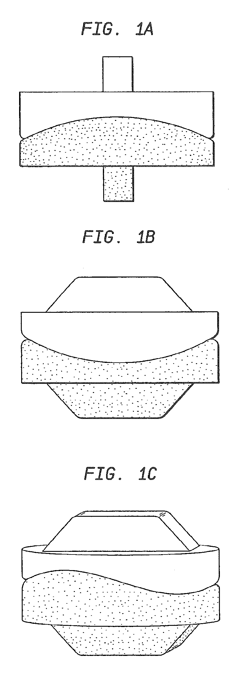
[0010] FIG. 1A is an anterior view of an ADR according to the invention;
[0011] FIG. 1B is a lateral view of the ADR of FIG. 1;
[0012] FIG. 1C is an oblique view of the ADR of FIG. 1;
[0013] FIG. 1D is a lateral view of the ADR of FIG. 1 representing a center of rotation defined by an articular surface of the ADR.
[0014] FIG. 1E is an anterior view of the ADR of FIG. 1 representing another center of rotation defined by another articular surface of the ADR.
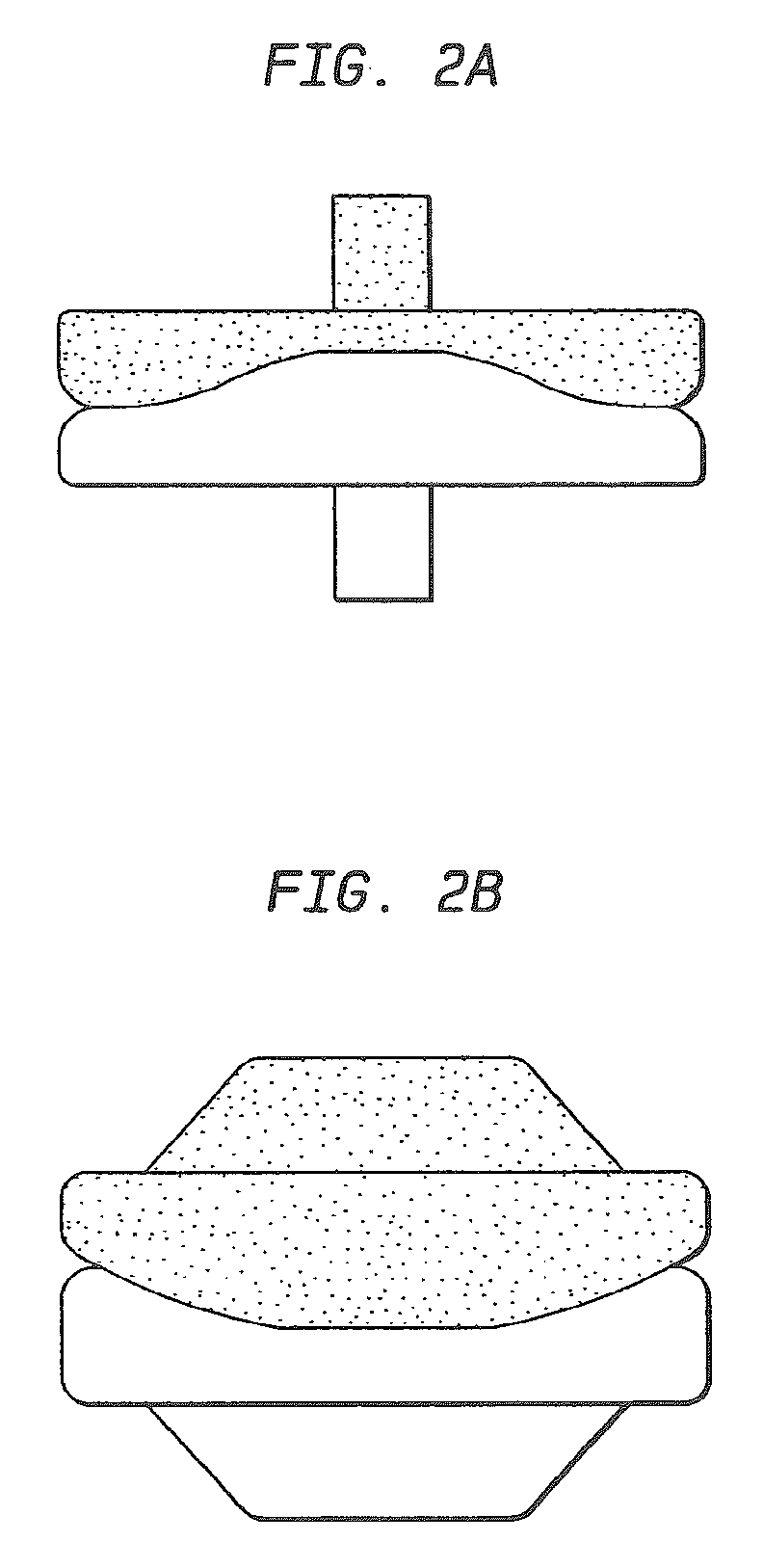
[0015] FIG. 2A is a view of the anterior aspect of an alternative embodiment of the ADR;
[0016] FIG. 2B is a view of the lateral aspect of an alternative embodiment of the ADR shown in FIG. 2B;
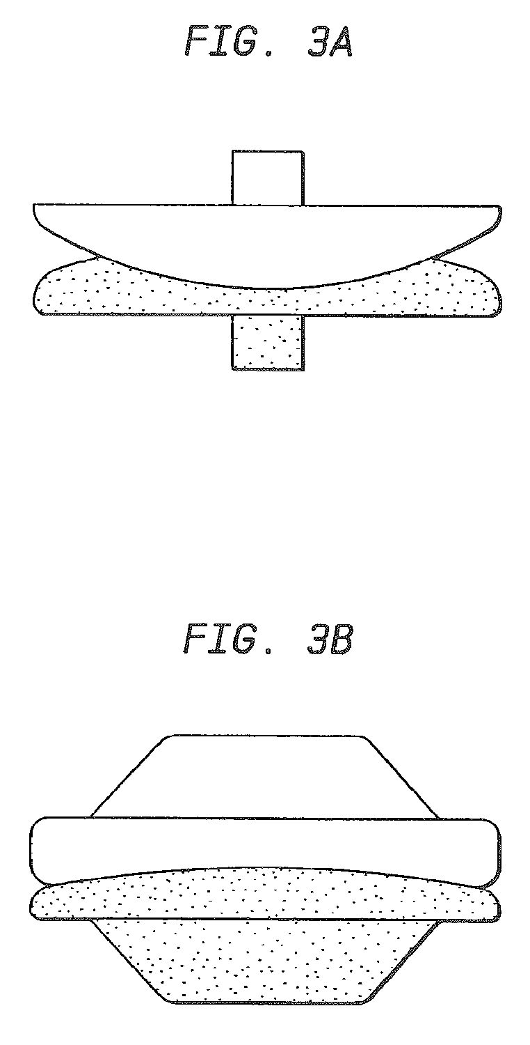
[0017] FIG. 3A is a view of the anterior aspect of an alternative, less constrained, embodiment of the saddle-shaped ADR shown in a fully flexed position;
[0018] FIG. 3B is a view of the lateral aspect of the embodiment of the ADR shown in FIG. 3A;
[0019] FIG. 4A is a view of the lateral aspect of another embodiment of a saddle-shaped ADR;
[0020] FIG. 4B is a view of the anterior aspect of the embodiment of the ADR shown in FIG. 4A in a fully flexed position;
[0021] FIG. 4C is a view of the anterior aspect of an alternative embodiment;
[0022] FIG. 4D is a view of the anterior aspect of the ADR shown in FIG. 4A; and
[0023] FIG. 4E is a view of the anterior aspect of the ADR shown in FIG. 4A.
DETAILED DESCRIPTION OF THE INVENTION
[0024] FIG. 1A is an anterior view of an ADR according to the invention. FIG. 1B is a lateral view of the ADR of FIG. 1. FIG. 1C is an oblique view of the ADR of FIG. 1.
[0025] FIG. 2A is a view of the anterior aspect of an alternative embodiment of the ADR, wherein the articulating surfaces of both components have a flat area centrally from the front to the back of the ADR. FIG. 2B is a view of the lateral aspect of an alternative embodiment of the ADR drawn in FIG. 2B. The flat area of the articulating surfaces courses centrally from side of the DR to the other side. The flat area allows one component to translate slightly on the other component. Alternatively, a curved area with a large radius could replace the flat area.
[0026] FIG. 3A is a view of the anterior aspect of an alternative, less constrained, embodiment of the saddle-shaped ADR drawn in a fully flexed position. The less constrained embodiment facilitates spinal flexion, extension, and lateral bending. FIG. 3B is a view of the lateral aspect of the embodiment of the ADR drawn in FIG. 3A.
[0027] FIG. 4A is a view of the lateral aspect of another embodiment of a saddle-shaped ADR. The center of rotation for flexion and extension is not necessarily located in the center of the ADR. For example, the center of rotation is preferably located in the posterior half of the ADR. FIG. 4B is a view of the anterior aspect of the embodiment of the ADR drawn in FIG. 4A, drawn in a fully flexed position.
[0028] FIG. 4C is a view of the anterior aspect of an alternative embodiment, showing how the radius of curvature of the articulation for lateral bending may be different than the radius of curvature for articulation for flexion and extension. For example, the radius of curvature for the articulation for flexion and extension, as seen in FIG. 4A, may be smaller than the radius of curvature for the articulation for lateral bending, as seen in FIG. 4C. Articulating surfaces with smaller radii, facilitate movement. Thus, the embodiment of the ADR drawn in FIG. 4A flexes and extends more easily than the embodiment of the ADR drawn in FIG. 3A. The ADR is drawn in a fully flexed position.
[0029] FIG. 4D is a view of the anterior aspect of the ADR drawn in FIG. 4A. The ADR is drawn in a neutral position. The area of the drawing with diagonal lines represents the articulating surface of the lower ADR component. FIG. 4E is a view of the anterior aspect of the ADR drawn in FIG. 4A, also drawn in a fully extend position.
* * * * *
D00000
D00001
D00002
D00003
D00004
D00005
D00006
XML
uspto.report is an independent third-party trademark research tool that is not affiliated, endorsed, or sponsored by the United States Patent and Trademark Office (USPTO) or any other governmental organization. The information provided by uspto.report is based on publicly available data at the time of writing and is intended for informational purposes only.
While we strive to provide accurate and up-to-date information, we do not guarantee the accuracy, completeness, reliability, or suitability of the information displayed on this site. The use of this site is at your own risk. Any reliance you place on such information is therefore strictly at your own risk.
All official trademark data, including owner information, should be verified by visiting the official USPTO website at www.uspto.gov. This site is not intended to replace professional legal advice and should not be used as a substitute for consulting with a legal professional who is knowledgeable about trademark law.