Valved Sheath Introducer For Venous Cannulation
Christensen; Mark A. ; et al.
U.S. patent application number 16/422716 was filed with the patent office on 2019-09-12 for valved sheath introducer for venous cannulation. The applicant listed for this patent is C. R. Bard, Inc.. Invention is credited to James D. Beal, Mark A. Christensen, Walter H. Shang, Steven M. Smith.
| Application Number | 20190274722 16/422716 |
| Document ID | / |
| Family ID | 34968154 |
| Filed Date | 2019-09-12 |


| United States Patent Application | 20190274722 |
| Kind Code | A1 |
| Christensen; Mark A. ; et al. | September 12, 2019 |
Valved Sheath Introducer For Venous Cannulation
Abstract
A valved sheath introducer for venous cannulation, including a valve, sheath, handle and cap. The valve is configured to permit safe introduction and removal of medical instruments through the sheath introducer. The valve may have one or more anchoring members and a thickened central portion through which a slit is formed. The central portion may have one or more concave surfaces and the slit can be angled with respect to the top surface of the valve. The cap is attached to the handle, compressing a portion of the valve therebetween.
| Inventors: | Christensen; Mark A.; (Salt Lake City, UT) ; Shang; Walter H.; (Irvine, CA) ; Smith; Steven M.; (Sandy, UT) ; Beal; James D.; (South Jordan, UT) | ||||||||||
| Applicant: |
|
||||||||||
|---|---|---|---|---|---|---|---|---|---|---|---|
| Family ID: | 34968154 | ||||||||||
| Appl. No.: | 16/422716 | ||||||||||
| Filed: | May 24, 2019 |
Related U.S. Patent Documents
| Application Number | Filing Date | Patent Number | ||
|---|---|---|---|---|
| 14749514 | Jun 24, 2015 | 10307182 | ||
| 16422716 | ||||
| 12648533 | Dec 29, 2009 | 9108033 | ||
| 14749514 | ||||
| 11119599 | May 2, 2005 | 7637893 | ||
| 12648533 | ||||
| 60566896 | Apr 30, 2004 | |||
| Current U.S. Class: | 1/1 |
| Current CPC Class: | Y10T 137/788 20150401; Y10T 137/7885 20150401; Y10T 29/49405 20150115; Y10T 29/49826 20150115; A61B 17/3415 20130101; A61M 39/0693 20130101; A61M 25/0662 20130101; Y10T 29/49412 20150115; A61B 17/3498 20130101 |
| International Class: | A61B 17/34 20060101 A61B017/34; A61M 39/06 20060101 A61M039/06 |
Claims
1. A method of making a sheath introducer, comprising: coupling a handle to a sheath having a lumen, the handle including: a bore communicating with the lumen; a first receiving section; and a second receiving section; inserting a valve into the handle, comprising: inserting a central portion of the valve into the bore, the central portion having a first thickness, the central portion including a slit through the first thickness; inserting a first anchoring member of the valve into the first receiving section, the first anchoring member having a second thickness; and inserting a second anchoring member of the valve into the second receiving section, the second anchoring member having the second thickness; and attaching a cap to the handle under pressure to compress a portion of the valve between the cap and the handle.
2. The method of making according to claim 1, wherein the coupling step comprises insert molding the handle over a proximal end of the sheath.
3. The method of making according to claim 1, wherein the first receiving section of the handle is on a first side of the bore, and wherein the second receiving section of the handle is on a second side of the bore opposite of the first side of the bore.
4. The method of making according to claim 1, wherein the central portion of the valve has a thickness greater than a portion of the valve surrounding the central portion.
5. The method of making according to claim 1, wherein the central portion of the valve has a concave surface on one side thereof.
6. The method of making according to claim 5, wherein the central portion of the valve has opposing concave surfaces.
7. The method of making according to claim 1, wherein the central portion of the valve has a diameter approximately equal to a diameter of the bore of the handle.
8. The method of making according to claim 1, wherein the handle includes opposing slotted regions between the first receiving section and the second receiving section.
9. The method of making according to claim 8, wherein the slit of the valve is perpendicularly aligned with the opposing slotted regions.
10. The method of making according to claim 9, further comprising looping a wire through the slit, wherein the inserting step comprises disposing both a first end of the wire and a second end of the wire in either the first receiving section or the second receiving section of the handle.
11. The method of making according to claim 1, wherein the slit forms an acute angle with respect to a top surface of the valve.
12. The method of making according to claim 1, wherein the slit of the valve is positioned in a center of the central portion, and wherein the valve further comprises a second slit aligned with the slit, the second slit positioned at an outer edge of the valve.
13. The method of making according to claim 12, wherein the valve further comprises a third slit aligned with the slit, and wherein the third slit is positioned at a first edge of the valve and the second slit is positioned at a second edge of the valve opposite of the first edge of the valve.
14. The method of making according to claim 13, wherein the handle includes opposing slotted regions between the first receiving section and the second receiving section, and wherein the second slit and the third slit are aligned with the opposing slotted regions.
15. The method of making according to claim 1, wherein the slit of the valve is positioned in a center of the central portion, and wherein the valve further comprises a first notch aligned with the slit, the first notch positioned at an outer edge of the valve.
16. The method of making according to claim 15, wherein the valve further comprises a second notch aligned with the slit, wherein the first notch is positioned at a first edge of the valve and the second notch is positioned at a second edge of the valve opposite of the first edge of the valve.
17. The method of making according to claim 16, wherein the handle includes opposing slotted regions between the first receiving section and the second receiving section, and wherein the first notch and the second notch are aligned with the opposing slotted regions.
18. The method of making according to claim 1, wherein the attaching step comprises ultrasonically welding the cap to the handle.
19. The method of making according to claim 1, wherein the coupling step comprises coupling a first part of the cap to a first side of the handle and attaching a second part of the cap to a second side of the handle such that a gap between the first part of the cap and the second part of the cap is aligned with one or more slotted regions in the handle.
20. The method of making according to claim 1, wherein the first thickness is less than the second thickness.
Description
CROSS-REFERENCE TO RELATED APPLICATIONS
[0001] This application is a continuation of U.S. patent application Ser. No. 14/749,514, filed Jun. 24, 2015, now U.S. Pat. No. 10,307,182, which is a division of U.S. patent application Ser. No. 12/648,533, filed Dec. 29, 2009, now U.S. Pat. No. 9,108,033, which is a division of U.S. patent application Ser. No. 11/119,599, filed May 2, 2005, now U.S. Pat. No. 7,637,893, which claims the benefit of U.S. Provisional Application No. 60/566,896, filed Apr. 30, 2004, each of which is expressly incorporated by reference as if fully set forth herein.
BACKGROUND OF THE INVENTION
[0002] Introducer devices are commonly utilized for inserting medical devices, such as venous access catheters, into patients. Typically, such introducer devices comprise a peel-away sheath and a hub/handle assembly which is used in conjunction with a dilator assembly to access the vein of a patient, following insertion of a needle and guidewire. In particular, procedures for introducing a catheter into a blood vessel include the cut-down method and the Seldinger technique. The Seldinger technique involves first inserting a needle through the skin of a patient and into a vein to be catheterized, inserting a guidewire through the needle and into the vein, removing the needle from the guidewire and inserting the dilator and introducer sheath over the guidewire and into the vein, simultaneously removing the dilator and guidewire from the introducer sheath, inserting a catheter through the introducer sheath and into position within the accessed vein. Following insertion of the catheter, the introducer sheaths are generally designed such that they can be peeled away from the catheter, without affecting the catheter positioning within the vein. Such introducer sheaths and assemblies are described, for example, in U.S. Pat. No. 4,772,266 to Groshong, issued Sep. 20, 1988, and U.S. Pat. No. 4,306,562 to Osborne, issued Dec. 21, 1981, each of which is incorporated by reference herein.
[0003] Problems, however, with the above-described procedure include, 1) that upon removal of the dilator and guidewire from the sheath, blood loss through the sheath can occur, and 2) that the introducer sheath provides a conduit for the introduction of air into the patient's vein, which can result in air embolism. Moreover, the risk of air embolism increases in proportion to the diameter size of the indwelling sheath, meaning that larger diameter sheaths routinely used for the placement of larger diameter catheters would increase such risk. Thus, there have been a variety of solutions proposed, which involve the incorporation of a valve in the proximal end of the introducer sheath, which would allow passage of a guidewire and dilator while simultaneously preventing blood loss or the introduction of air through the sheath. Such proposed solutions can be found, for example, in U.S. Pat. No. 5,125,904 to Lee, issued Jun. 30, 1992, U.S. Pat. No. 5,397,311 to Walker et al., issued Mar. 14, 1995, U.S. Pat. No. 6,083,207 to Heck, issued Jul. 4, 2000, each of which is incorporated by reference herein.
[0004] The aforementioned and similarly directed patents are concerned primarily with providing an elastic valve structure that provides hemostasis and the prevention of blood loss or bleed back for arterial cannulation procedures where there is significant positive blood pressure. On the other hand, with respect to venous cannulation, blood pressure is much lower and negative pressures may be involved, meaning that while prevention of blood loss is an ancillary concern, it is the prevention of air embolism that is the most crucial consideration. Thus, there exists the need for a valved sheath introducer designed for particular use for venous cannulation.
BRIEF SUMMARY OF THE INVENTION
[0005] Accordingly, the present invention is directed to a valved sheath introducer for venous cannulation. In one embodiment of the invention, the valve in the introducer includes a thin disk with a central slit and includes features such as opposing anchors to allow stretching of the disk when a medical device is inserted therethrough, a thickened central portion through which a self-sealing slit is positioned, which promotes optimal resealing upon removal of a medical device, and mechanical or other means of splitting the disk simultaneous to the breaking and separating of a sheath handle from an inserted medical device. In one embodiment, the thickened central portion or island has a concave surface. Some embodiments of the valve include slits or notches aligned with the central slit to facilitate separation of the valve when the sheath and handle are removed from an inserted medical device.
[0006] In another embodiment of the invention, an apparatus for insertion of a medical device into a body comprises a sheath comprising a sheath body and a handle, the handle including at least one receiving section, a valve comprising a slit through a central portion thereof and at least one anchoring member configured for insertion into the handle receiving section, the anchoring member being positioned along an edge of the valve, and a cap attached to the handle, at least a portion of the valve being compressed therebetween. In another embodiment, a wire is looped through a slit positioned in the valve, such that when the handle is separated and removed from medical device inserted through the valved sheath introducer, the wire cuts the valve into two portions.
[0007] In one aspect of the valved sheath introducer, the valve is designed to provide optimal sealing when removing an instrument, such as a dilator. The optimal sealing occurs due to the configuration of the valve, such as a central portion or island and one or more anchoring members, and the way in which the valve is tightly held between a handle and a cap. Thus, upon removal of an instrument from the introducer sheath, the valve body, which is stretched as the instrument is inserted therethrough, rebounds toward the handle but cannot resume its original position due to the pressure exerted by the cap and the handle. The result is a bunching or duckbill effect of the valve that provides a desirable seal.
[0008] These and other embodiments, features and advantages of the present invention will become more apparent to those skilled in the art when taken with reference to the following more detailed description of the invention in conjunction with the accompanying drawings that are first briefly described.
BRIEF DESCRIPTION OF THE DRAWINGS
[0009] FIG. 1 illustrates a side perspective view of one embodiment of a valved sheath introducer with an inserted dilator.
[0010] FIG. 2 illustrates a side perspective view of the sheath introducer of FIG. 1 in isolation.
[0011] FIG. 3 illustrates a top view of the handle of the sheath introducer of FIG. 2.
[0012] FIG. 4 illustrates a bottom view of one embodiment of a valve for a valved sheath introducer.
[0013] FIG. 5 illustrates a side view of the valve of FIG. 4.
[0014] FIGS. 6A and 6B illustrate a cross-sectional view of the valve of FIG. 4.
[0015] FIG. 7 illustrates a bottom view of another embodiment of a valve for a valved sheath introducer.
[0016] FIG. 8 illustrates a bottom view of yet another embodiment of a valve for a valved sheath introducer.
[0017] FIGS. 9A-9D illustrates an advantageous feature of one embodiment of a valve for a valved sheath introducer.
[0018] FIG. 10 depicts an alternate embodiment of a valve for a valved sheath introducer along with a handle and cap prior to assembly.
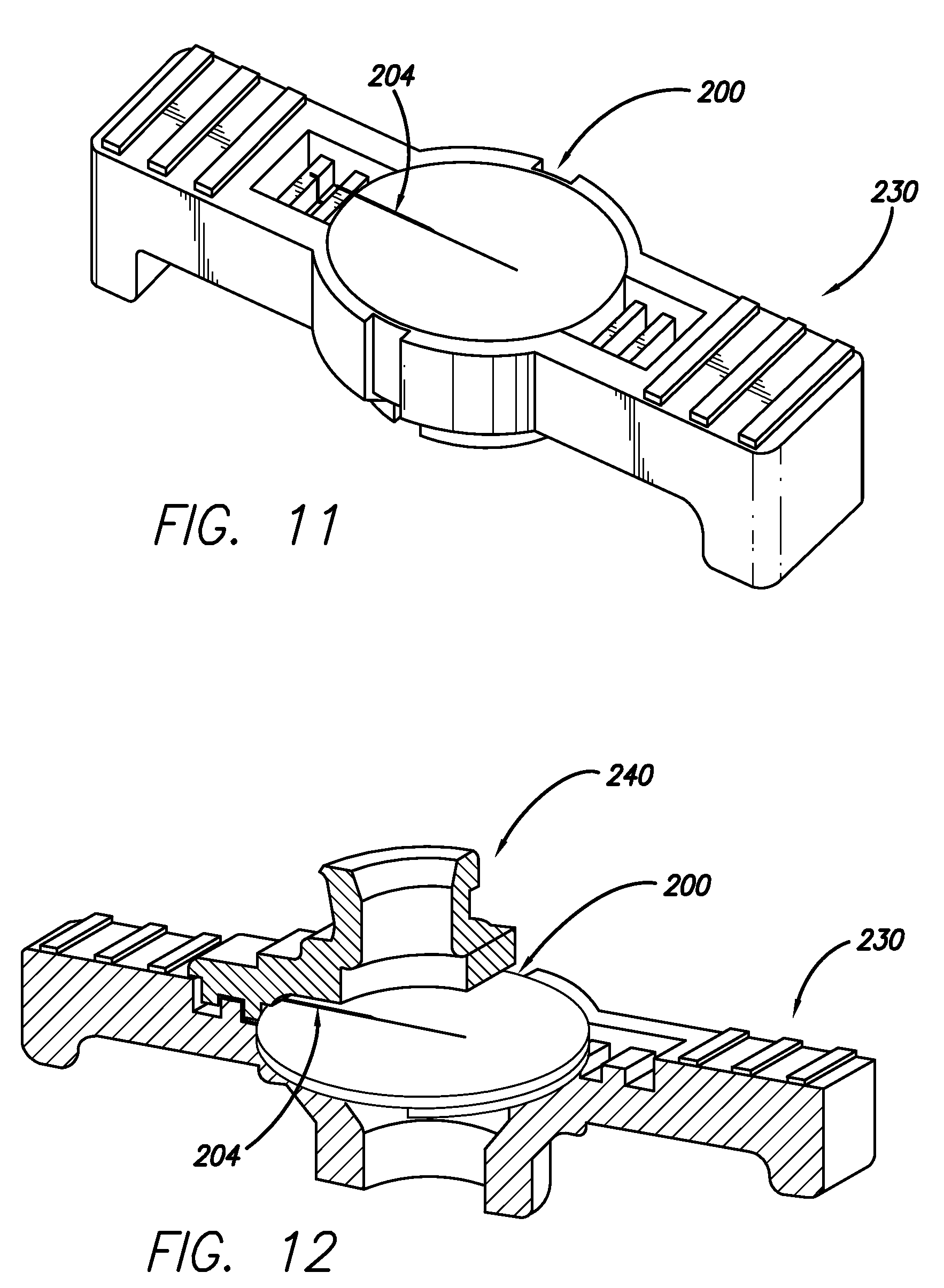
[0019] FIG. 11 depicts the valve of FIG. 10 in isolation with the handle.
[0020] FIG. 12 is a cross-sectional assembled view of the cap, handle and valve of FIG. 10.
[0021] FIG. 13 is a further cross-sectional view of the cap, handle and valve of FIG. 12.
[0022] FIG. 14 is an alternate embodiment of a valve with an island, the island having a concave surface.
[0023] FIG. 15 is a cross-sectional view of the valve of FIG. 14.
DETAILED DESCRIPTION OF THE INVENTION
[0024] The following detailed description should be read with reference to the drawings, in which like elements in different drawings are identically numbered. The drawings, which are not necessarily to scale, depict selected embodiments and are not intended to limit the scope of the invention. The detailed description illustrates by way of example, not by way of limitation, the principles of the invention. This description will clearly enable one skilled in the art to make and use the invention, and describes several embodiments, adaptations, variations, alternatives and uses of the invention, including what is presently believed to be the best mode of carrying out the invention.
[0025] The present invention involves valves and valved sheath introducers used particularly in venous cannulation procedures. However, it should be appreciated that while the designs described herein are intended for such use, they may be equally suitable for a variety of other uses (e.g., arterial cannulation, introduction of pacing leads, etc.) and therefore should not be so limited. Further, while sheath introducers and sheath introducer assemblies are described herein for exemplary purposes of housing and implementation of the subject valves, it should be appreciated that many different configurations and types of sheath introducers and sheath introducer assemblies would be equally suitable for use with the valves of the present invention and therefore should in no way serve to limit the scope of the valves described herein. In addition, as used in this specification and the appended claims, the singular forms "a," "an" and "the" include plural referents unless the context clearly dictates otherwise. Thus, for example, the term "a slit" is intended to mean a single slit or more than one slit.
[0026] Referring now to FIGS. 1 and 2, a valved sheath introducer assembly 10 according to one embodiment is shown, including a valved sheath introducer 20 and a dilator 50. The valved sheath introducer assembly 10 is shown in its insertion configuration with dilator 50 inserted completely through the valved sheath introducer 20 and locked thereto. The valved sheath introducer 20 includes a sheath body 22, a handle 30, a cap 40, and an internal valve 100 (FIG. 4). In this embodiment, the handle 30 has a first side 32 and a second side 34 separated by two slots 36, positioned approximately 180.degree. apart. The sheath body 22 has a tapered distal end 24 to facilitate insertion into a blood vessel. In one embodiment, the sheath body 22 is made of polytetrafluoroethylene (PTFE) and the handle 30 and cap 40 are made of K-Resin.RTM. (styrene-butadiene copolymer). In another embodiment, the handle 30 and cap 40 are made of Cryolite.RTM. (poly(methyl methacrylate)). Of course, other materials are also possible for the sheath body, handle and cap, including other polymer materials (e.g., polycarbonate, thermoplastics, etc.), as is apparent to one of ordinary skill in the art.
[0027] In an exemplary manufacturing process for the valved sheath introducer 20, the handle 30 is insert molded over the proximal end 26 of the sheath body 22. After molding, the valve 100 is placed on the top of the handle 30, and the cap 40 is attached to the handle 30 (e.g., via ultrasonic weld, adhesives, screws, etc.) over the valve 100 under force. In one exemplary manufacturing method, the attachment method is ultrasonic welding wherein the sheath body 22 and handle 30 are placed into an ultrasonic welder and the cap 40 is pressed onto the handle 30 after the valve 100 has been set therein. The ultrasonic welder sends vibrations through the cap 40, causing a portion of the cap 40 and handle 30 to meld together. In one embodiment, the cap 40 is in two part form prior to welding such that a small gap in alignment with the slots 36 can be provided. In a top view of the handle 30, shown in FIG. 3 prior to attachment of the valve 100 and cap 40, slots 36 can be seen in more detail as can the handle bore 39, which is configured to be approximately the same diameter as that of the lumen of the valved sheath introducer 20. In addition, valve receiving sections 38 can be seen configured to accommodate valve anchors 102, 104 (FIG. 4), as will be explained in more detail below.
[0028] Referring back to FIG. 1, the dilator 50 includes a threaded luer connector 52, which rotates independently of the dilator body 56, and is configured for mating with the cap 40 to lock the dilator 50 to the valved sheath introducer 20. The body 56 has a diameter approximately equal to that of the lumen of the valved sheath introducer 20 and also has a tapered distal end 58 to provide ease of insertion of the valved sheath introducer assembly 10 into a blood vessel. The dilator 50 also includes a luer connection 54 at the proximal end thereof for attachment to devices used for purposes such as flushing. An injection cap (not shown) may also be placed over the proximal end of the dilator.
[0029] FIGS. 4-6B illustrate one embodiment of a valve 100 for incorporation into a valved sheath introducer. FIG. 4 is a bottom view of valve 100, which is a thin disk-like body 108, including valve anchors 102, 104 around the circumferential edge of the body 108 and disposed on the back side thereof. The valve anchors 102, 104 extend from the body 108, as can be seen in FIGS. 5 and 6A, and are configured in size and shape to correspond with the valve receiving sections 38 of the handle 30 (FIG. 3) to ensure that the valve 100 remains in axial position as instruments are inserted therethrough and withdrawn therefrom, and also to ensure that the valve 100 properly separates (each side of the valve remaining with its respective side of the handle into which it is held) upon removal of the sheath introducer 20 from an inserted instrument.
[0030] FIG. 6A is a cross-section of the valve of FIG. 4 taken along line 6A-6A, showing the relative thickness of the island 106 compared to the opposing anchors 102, 104. As shown in this embodiment, the island thickness is slightly less than that of the anchors, although in other embodiments, the island thickness is either the same or greater than the thickness of the anchors. In still other embodiments, the anchors 102, 104 have different thicknesses, each of which may be greater than, less than or equal to the island thickness. Also, in the embodiments shown, the anchors 102, 104 have rounded edges 116, although other configurations, including edges with opposing right angles, are certainly contemplated herein. FIG. 6B illustrates another embodiment of the valve 100, including a slit 110A that is cut through the middle region of the valve 100, traversing at an angle from a top surface of the valve to a bottom surface thereof (e.g., to a surface of the island 106) that is different from the approximately 90.degree. angle with respect to the top surface of the valve shown in FIG. 6A. While the slit 110A is shown as cut at approximately a 45.degree. angle, certainly any other non-parallel angle with respect to the top surface of the valve is possible as should be appreciated by one of ordinary skill in the art.
[0031] The anchors 102, 104 allow for a tight tolerance with respect to the positioning of the valve 100 within the handle 30, being tightly secured therein by the cap 40, as explained above. This tight tolerance results in an advantageous reaction by the valve 100 with respect to sealing thereof upon removal of an instrument that had previously been inserted therethrough (e.g., dilator, etc.). In particular, in concert with the island 106, which is a circular feature positioned in the center of the body 108, extending along with the anchors 102, 104 from the bottom thereof, a superior seal is created upon removal of an instrument from the sheath introducer 20, as will be explained below in connection with FIGS. 9A-9D. It should be appreciated that while the valve 100 has a circular shape and the valve anchors 102, 104 have a semi-circular shape, as seen in FIG. 4, various shapes and sizes are possible and contemplated herein to correspond with the shape and size of the handle and receiving sections onto/into which they are positioned.
[0032] In the embodiment shown in FIG. 4, approximately equidistantly spaced on the edge of the body 108 between the valve anchors 102, 104 on opposite sides of the body 108 are peripheral slits 112, 114, which enable the valve 100 to be easily split in half along the line extending from slit 112 to slit 114. These slits can also be in the form of notches having various shapes, two of which (122, 124 and 132, 134) are illustrated in FIGS. 7 and 8. While the notches shown are in the shapes of triangles and trapezoids, other shapes are possible and are contemplated herein to facilitate the separation of the valve 100. A central slit 110 through which instruments can be inserted is cut through the valve body 108 and island 106 and is positioned approximately centrally with respect to the edges of the valve 100. While only one slit is shown, in other embodiments two or more slits are formed through the valve in different patterns. For instance, in one embodiment, multiple slits are cut through the valve in a pattern similar to an asterisk when viewed from the top or bottom thereof. As discussed, when the valve 100 is placed into the handle 30, the valve anchors 102, 104 are positioned in receiving sections 38 of the handle 30, which places the island 106 within the opening of the handle bore 39. Such alignment results in the slits 112, 114 being aligned with the slots 36 of the handle 30.
[0033] The following materials and dimensions are provided as an example of one embodiment and should not be taken as limiting the invention in any way. The valve 100 in this embodiment is made of silicone (Dow Corning Q7-4840), having a diameter of approximately 0.516 inches, while the diameter of the island 106 is approximately 0.260 inches and the distance between inner edges of the islands 102, 104 is approximately 0.420 inches (the width of the anchors thus being approximately 0.048 inches). The thickness of the valve 100 along the anchors 102, 104 is approximately 0.090 inches, while the thickness of the valve across the island is approximately 0.045 inches, the remainder of the body therefore having a thickness of approximately 0.025 inches. The distance between the anchors 102, 104 is approximately 0.160 inches on both sides of the valve 100. The central slit 110 has a length of approximately 0.204 inches, while the peripheral slits 112, 114 have a length of approximately 0.050 inches. In other embodiments, the dimensions are dependent upon the size of the instrument(s) being inserted through the valve.
[0034] With respect to the valve island 106, another embodiment is shown in FIGS. 14 and 15. Valve 300 is shown, including one or more anchors 302 and an island 306 that has a concave surface 304 extending into the thickness of the valve body 308 and a slit 310. The slit 310 as shown is positioned at an angle of approximately 60.degree. with respect to the top surface of the valve, although as stated above in connection with FIGS. 6A and 6B, any other non-parallel angle with respect to the top surface of the valve is possible. The curvature of the concave surface can be more or less than shown and can extend short of, or up to, the line of the valve body in other embodiments. The depth of the concavity is also variable, which alters the thickness of the mid-point of the island in different embodiments. As shown in FIG. 15, the edges of the island are curved, although as with the anchors, other types of edges are possible. Numerous embodiments are contemplated with respect to the configuration of the island and slits or notches in the valve. For instance, the valve could have a concave surface on the island along with notches on opposing sides of the valve, the valve could have a concave surface on the island and an opposing concave surface on the top of the valve with no slits or notches, the valve could have notches or slits but no island, etc.
[0035] FIGS. 9A-9C depict the configuration of one side of the valve 100 with respect to the handle 30 and the cap 40 as an instrument is inserted therethrough (FIG. 9B) and withdrawn therefrom (FIG. 9C). An imaginary grid is provided to aid in the illustration of the movement and positioning of the valve 100 with respect to the handle 30 and the cap 40. It should be appreciated, however, that the grid is exemplary only and isn't intended to depict actual distances or precise intervals. In FIG. 9A, the valve 100 is tightly held between the handle and the cap prior to insertion of an instrument therethrough. Close inspection of the valve 100 reveals that the thickness of the valve material 150 between the handle 30 and the cap 40 is slightly less than the thickness of the valve material 160 outside of this area (i.e., within the handle bore 39). This is due to the pressure exerted onto the valve 100 as the cap 40 is attached to the handle 30 as explained above. As can be seen, the distance between the marks on the grid line in FIG. 9A are the same for both valve material 150 and 160.
[0036] FIG. 9B depicts the movement of the valve 100 upon insertion of an instrument therethrough, the valve material 160 stretching and experiencing a reduction in thickness such that the thickness thereof is approximately equivalent to the thickness of valve material 150 (although certainly the thickness of the valve material 160 could be greater than or equal to the valve material 150 as it is stretched upon insertion of an instrument through valve 100). In addition to the thickness of the valve, this demonstration of stretching is evidenced by the increased distance between the marks on the grid line along valve material 160. Although the valve material 150 is still held tightly between the cap 40 and the handle 30 while an instrument is inserted through the valve 100, stretching of the material does occur. This action is revealed in FIG. 9B by the grid line as the distance between the marks on the grid line is shown to increase. It is noted here that while the material adjacent to the anchors stretches slightly upon insertion of an instrument through the valve 100, the anchors themselves remain in position inside the receiving sections of the handle.
[0037] FIG. 9C depicts the valve 100 upon removal of the inserted instrument, at which point the valve material 150 and 160 rebounds back toward the side of the handle 30. However, because the valve material 150 is tightly held between the cap 40 and the handle 30, a bunching effect occurs as stretched valve material 150 that has moved from an original position between the handle 30 and cap 40 toward the center of the valved introducer 20 is prevented from returning to its original position. This phenomenon is illustrated by the grid line in FIG. 9C, which shows the distance between marks in valve material 150 to be approximately the same as the distance in FIG. 9B, whereas the distance between marks in valve material 160 has slightly decreased. This bunching effect leads to a duckbill-like configuration for the valve 100 as shown in FIG. 9D, which illustrates the configuration of the central region of the valve following removal of an instrument. Such a configuration provides a superior seal over the valves of the prior art. In one embodiment, the valve 100 is provided with a lubricant in order to ease the surface friction between the valve and inserted instrument, thus maintaining the desired duckbill shape.
[0038] Removal of the sheath introducer 20 from an instrument inserted therethrough (e.g., a catheter) is effectuated by grasping the handle 30 on each side thereof and pulling the sides in opposite directions so that the handle 30 cracks along the slots 36. Upon cracking and splitting of the handle 30, the integrated valve 100 tears along the slit line created by central slit 110 and peripheral slits 112, 114, the tearing process enabled, as discussed above, by the anchors 102, 104, which maintain the position of each side of the valve 100 within the respective side of the handle. As the two pieces of the handle are pulled away from one another, the sheath peels down its entire length at the circumferential location of the handle slots (which correspond to the aligned pre-split sections of the sheath). Due to the extrusion process for manufacturing the PTFE, which results in an alignment of the molecules, the peeling of the sheath is continuous down the entire length thereof at the circumferential locations without the need for score line(s). The handle does not detach from the sheath during or after the splitting process. In other embodiments of the invention, the sheath is made from PTFE or another like polymer material with one or more score lines positioned longitudinally along the length of the sheath in line with the slot(s) in the handle.
[0039] In another embodiment of a valved sheath introducer, a very thin wire is associated with the valve, as shown in FIGS. 10-13. FIG. 10 illustrates a handle 230, a cap 240 and a valve 200, which includes a single anchor 202 and a thin wire 204, prior to assembly. The wire 204 is looped through the central slit of the valve 200 and each end extends beyond the edge of the valve 200, being coupled together for positioning in the handle 230. The central slit of valve 200 is oriented perpendicular to the slots of the handle 230, differently than the axial alignment of valve 100 described above. It should be noted that in this view, the cap 240 has an extension pattern 242 configured to be received within a like shaped extension pattern in the handle 230 for an improved connection therebetween. FIG. 11 illustrates the valve 200 placed into the handle 30. FIG. 12 illustrates the interaction of the handle 230, cap 240 and valve 200 by showing a cutaway view of the cap 240 and handle 230 with a top perspective view of the valve, while FIG. 13 shows another cutaway view of the handle 230 and cap 240 with a cross-sectional view of the valve 200 also being shown.
[0040] In FIG. 13, the side of the handle 230 that receives the wire 204 can be seen to also have an empty receiving section 238 due to the fact that the valve 200 does not contain an anchor for positioning therein. While in some embodiments, this empty section does not exist, in this particular embodiment the presence of receiving sections in both sides of the handle 230 facilitates manufacture of the valved sheath introducer by permitting positioning of the anchor 202 in either side of the handle. When the handle 230 is broken to remove from an inserted instrument (e.g., a catheter), the wire 204 remains with the half of the handle 230 into which the extension thereof has been set (FIG. 11), while the valve 200 remains with the opposite half, into which the anchor 202 is set (FIGS. 12, 13). Thus, as the halves of the handle 230 are pulled in opposite directions, the wire 202 cuts the valve 200, slicing it into two parts for easy removal from the inserted instrument.
[0041] The valved sheath introducer described herein is used according to one embodiment as follows. After an access site on a body is determined and an incision made, the valved sheath introducer assembly is inserted into the body with a distal end of the sheath body extending into a body vessel to be accessed. Following optional preparatory steps (e.g., flushing), the dilator is removed from the valved sheath introducer. As the dilator is removed, the valve closes as described above in connection with FIGS. 9A-9C. A catheter or other medical device can then be inserted through the valved sheath introducer and into the body vessel. When the desired positioning of a more permanent medical device, such as a catheter, has been accomplished, the valved sheath introducer is ready to be removed. In one embodiment, the handle is cracked by pulling a first side and a second side of the handle in opposite directions (i.e., away from the inserted medical device). This cracking action may take place, for example, along slots positioned in the handle between the first and second sides. By pulling the handle apart, the valve is separated such that one portion remains with the first side of the handle and another portion remains with the second side of the handle, as is described in exemplary embodiments herein. Once the handle is broken and the first and second sides are continued to be pulled in approximately opposite directions away from the inserted medical device, the sheath body is torn down its length so that complete removal of the valved sheath introducer from around the inserted medical device is possible without affecting the positioning of the medical device in the body vessel.
[0042] This invention has been described and specific examples of the invention have been portrayed. While the invention has been described in terms of particular variations and illustrative figures, those of ordinary skill in the art will recognize that the invention is not limited to the variations or figures described. In addition, where methods and steps described above indicate certain events occurring in certain order, those of ordinary skill in the art will recognize that the ordering of certain steps may be modified and that such modifications are in accordance with the variations of the invention. Additionally, certain of the steps may be performed concurrently in a parallel process when possible, as well as performed sequentially as described above. Therefore, to the extent there are variations of the invention, which are within the spirit of the disclosure or equivalent to the inventions found in the claims, it is the intent that this patent covers those variations as well. Finally, all publications and patent applications cited in this specification are herein incorporated by reference in their entirety as if each individual publication or patent application were specifically and individually put forth herein.
* * * * *
D00000
D00001
D00002
D00003
D00004
D00005
D00006
D00007
D00008
D00009
XML
uspto.report is an independent third-party trademark research tool that is not affiliated, endorsed, or sponsored by the United States Patent and Trademark Office (USPTO) or any other governmental organization. The information provided by uspto.report is based on publicly available data at the time of writing and is intended for informational purposes only.
While we strive to provide accurate and up-to-date information, we do not guarantee the accuracy, completeness, reliability, or suitability of the information displayed on this site. The use of this site is at your own risk. Any reliance you place on such information is therefore strictly at your own risk.
All official trademark data, including owner information, should be verified by visiting the official USPTO website at www.uspto.gov. This site is not intended to replace professional legal advice and should not be used as a substitute for consulting with a legal professional who is knowledgeable about trademark law.