Start Temperature Of Blade
Gee; Jacob S. ; et al.
U.S. patent application number 16/144483 was filed with the patent office on 2019-09-12 for start temperature of blade. The applicant listed for this patent is Ethicon LLC. Invention is credited to Jacob S. Gee, Cameron R. Nott.
| Application Number | 20190274720 16/144483 |
| Document ID | / |
| Family ID | 67842845 |
| Filed Date | 2019-09-12 |


View All Diagrams
| United States Patent Application | 20190274720 |
| Kind Code | A1 |
| Gee; Jacob S. ; et al. | September 12, 2019 |
START TEMPERATURE OF BLADE
Abstract
A method of determining an initial temperature of an ultrasonic blade may include measuring a resonant frequency of an ultrasonic blade prior to activating an ultrasonic transducer, in which the ultrasonic transducer is coupled to the blade via an ultrasonic waveguide, comparing the measured resonant frequency to a baseline resonant frequency, determining an initial temperature of the ultrasonic blade based on a difference between the measured resonant frequency and the baseline resonant frequency, and applying a power level to the blade based on the initial temperature of the blade. The method may further include applying a high power level to the transducer when the initial temperature of the ultrasonic blade is low or applying a low power level to the transducer when the initial temperature of the blade is high. The baseline resonant frequency may be stored in a memory look up table.
| Inventors: | Gee; Jacob S.; (Cincinnati, OH) ; Nott; Cameron R.; (Loveland, OH) | ||||||||||
| Applicant: |
|
||||||||||
|---|---|---|---|---|---|---|---|---|---|---|---|
| Family ID: | 67842845 | ||||||||||
| Appl. No.: | 16/144483 | ||||||||||
| Filed: | September 27, 2018 |
Related U.S. Patent Documents
| Application Number | Filing Date | Patent Number | ||
|---|---|---|---|---|
| 62640417 | Mar 8, 2018 | |||
| 62640415 | Mar 8, 2018 | |||
| Current U.S. Class: | 1/1 |
| Current CPC Class: | A61B 2017/00022 20130101; A61B 2017/00026 20130101; A61B 2218/002 20130101; A61B 2017/00061 20130101; A61B 2017/0084 20130101; A61B 2018/00601 20130101; A61B 2090/066 20160201; A61B 18/1206 20130101; A61B 2017/00084 20130101; A61B 2017/00106 20130101; A61B 2017/00137 20130101; A61B 2018/00892 20130101; A61B 2090/0811 20160201; A61B 2017/00221 20130101; A61B 18/1445 20130101; A61B 18/1233 20130101; A61B 2018/00619 20130101; A61B 2018/00684 20130101; A61B 17/320068 20130101; A61B 2017/22014 20130101; A61B 2017/2825 20130101; A61B 17/320092 20130101; A61B 17/22012 20130101; A61B 2017/00115 20130101; A61B 17/00234 20130101; A61B 18/12 20130101; A61B 34/30 20160201; A61B 2017/00017 20130101; A61B 2017/320074 20170801; A61B 2017/00075 20130101; A61B 2018/00827 20130101; A61B 2018/00886 20130101; A61B 90/361 20160201; A61B 2018/00607 20130101; A61B 2090/065 20160201; A61B 18/14 20130101; A61B 2017/320095 20170801; A61B 2218/008 20130101; A61B 2017/320084 20130101; A61B 2018/00595 20130101; A61B 2018/00875 20130101; A61B 2018/1253 20130101; A61B 2090/0809 20160201; A61B 2017/00464 20130101; A61B 2018/00589 20130101; A61B 2018/128 20130101; A61B 2017/00146 20130101; A61B 2018/00994 20130101; A61B 2018/1452 20130101; A61B 2018/126 20130101; A61B 18/1442 20130101; A61B 2017/320073 20170801; A61B 2017/00039 20130101; A61B 2017/00477 20130101; A61B 2017/32007 20170801; A61B 2017/320094 20170801; A61B 17/282 20130101; A61B 2017/00482 20130101; A61B 2018/0063 20130101; A61B 17/3211 20130101; A61B 2017/00398 20130101; A61B 2017/00199 20130101; A61B 2018/00702 20130101; A61B 2018/1412 20130101; A61B 2017/0003 20130101; A61B 2017/320097 20170801; A61B 2018/00648 20130101; A61B 2034/107 20160201; A61B 2018/00791 20130101; A61B 2090/0808 20160201; A61B 2217/005 20130101 |
| International Class: | A61B 17/32 20060101 A61B017/32; A61B 18/14 20060101 A61B018/14 |
Claims
1. A method of determining an initial temperature of an ultrasonic blade, the method comprising: measuring a resonant frequency of an ultrasonic blade prior to activating an ultrasonic transducer, wherein the ultrasonic transducer is coupled to the ultrasonic blade via an ultrasonic waveguide; comparing the measured resonant frequency to a baseline resonant frequency; determining an initial temperature of the ultrasonic blade based on a difference between the measured resonant frequency and the baseline resonant frequency; and applying a power level to the ultrasonic blade based on the initial temperature of the ultrasonic blade.
2. The method of claim 1, further comprising applying a high power level to the ultrasonic transducer to increase a temperature of the ultrasonic blade when the initial temperature of the ultrasonic blade is low.
3. The method of claim 1, further comprising applying a low power level to the ultrasonic transducer to decrease a temperature of the ultrasonic blade when the initial temperature of the ultrasonic blade is high.
4. The method of claim 1, further comprising storing the baseline resonant frequency in a memory look up table; and retrieving the baseline resonant frequency from the memory look up table.
5. The method of claim 4, wherein storing the baseline resonant frequency in a memory look up table comprises: measuring a resonant frequency of the ultrasonic blade at room temperature or at a predetermined ambient temperature; and storing the measured resonant frequency of the ultrasonic blade in a memory look up table.
6. The method of claim 1, further comprising generating a transfer function based on the baseline resonant frequency.
7. An ultrasonic surgical instrument comprising: an ultrasonic electromechanical system comprising an ultrasonic transducer coupled to an ultrasonic blade via an ultrasonic waveguide; and a generator configured to supply power to the ultrasonic transducer, wherein the generator comprises a control circuit configured to: measure a resonant frequency of an ultrasonic blade prior to activating an ultrasonic transducer, wherein the ultrasonic transducer is coupled to the ultrasonic blade via an ultrasonic waveguide; compare the measured resonant frequency to a baseline resonant frequency; determine an initial temperature of the ultrasonic blade based on a difference between the measured resonant frequency and the baseline resonant frequency; and apply a power level to the ultrasonic blade based on the initial temperature of the ultrasonic blade.
8. The ultrasonic surgical instrument of claim 7, wherein the control circuit is further configured to apply a high power level to the ultrasonic transducer to increase a temperature of the ultrasonic blade when the initial temperature of the ultrasonic blade is low.
9. The ultrasonic surgical instrument of claim 7, wherein the control circuit is further configured to apply a low power level to the ultrasonic transducer to decrease a temperature of the ultrasonic blade when the initial temperature of the ultrasonic blade is high.
10. The ultrasonic surgical instrument of claim 7, wherein the control circuit is further configured to store the baseline resonant frequency in a memory look up table, and retrieve the baseline resonant frequency from the memory look up table.
11. The ultrasonic surgical instrument of claim 10, wherein the baseline resonant frequency is derived from one or more ultrasonic blade measurements made at room temperature or at a predetermined ambient temperature.
12. The ultrasonic surgical instrument of claim 7, wherein the control circuit is further configured to generate a transfer function based on the baseline resonant frequency.
13. A generator for an ultrasonic surgical instrument, the generator comprising: a control circuit configured to: measure a resonant frequency of an ultrasonic blade prior to activating an ultrasonic transducer, wherein the ultrasonic transducer is coupled to the ultrasonic blade via an ultrasonic waveguide; compare the measured resonant frequency to a baseline resonant frequency; determine an initial temperature of the ultrasonic blade based on a difference between the measured resonant frequency and the baseline resonant frequency; and apply a power level to the ultrasonic blade based on the initial temperature of the ultrasonic blade.
14. The generator of claim 13, wherein the control circuit is further configured to apply a high power level to the ultrasonic transducer to increase a temperature of the ultrasonic blade when the initial temperature of the ultrasonic blade is low.
15. The generator of claim 13, wherein the control circuit is further configured to apply a low power level to the ultrasonic transducer to decrease a temperature of the ultrasonic blade when the initial temperature of the ultrasonic blade is high.
16. The generator of claim 13, wherein the control circuit is further configured to store the baseline resonant frequency in a memory look up table; and retrieve the baseline resonant frequency from the memory look up table.
17. The generator of claim 16, wherein the baseline resonant frequency stored in the memory look up table comprises a resonant frequency of the ultrasonic blade measured at room temperature or at a predetermined ambient temperature.
18. The generator of claim 13, wherein the control circuit is further configured to generate a transfer function based on the baseline resonant frequency.
19. An ultrasonic surgical system, comprising: a processor and a non-transitory memory, wherein the non-transitory memory comprises instructions that, when executed by the processor, cause the processor to: measure a resonant frequency of an ultrasonic blade prior to activating an ultrasonic transducer, wherein the ultrasonic transducer is coupled to the ultrasonic blade via an ultrasonic waveguide; compare the measured resonant frequency to a baseline resonant frequency; determine an initial temperature of the ultrasonic blade based on a difference between the measured resonant frequency and the baseline resonant frequency; and apply a power level to the ultrasonic blade based on the initial temperature of the ultrasonic blade.
Description
CROSS-REFERENCE TO RELATED APPLICATIONS
[0001] This application claims the benefit of priority under 35 U.S.C. .sctn. 119(e) to U.S. Provisional Patent Application Ser. No. 62/640,417, titled TEMPERATURE CONTROL IN ULTRASONIC DEVICE AND CONTROL SYSTEM THEREFOR, filed Mar. 8, 2018, and to U.S. Provisional Patent Application Ser. No. 62/640,415, titled ESTIMATING STATE OF ULTRASONIC END EFFECTOR AND CONTROL SYSTEM THEREFOR, filed Mar. 8, 2018, the disclosure of each of which is herein incorporated by reference in its entirety.
BACKGROUND
[0002] In a surgical environment, smart energy devices may be needed in a smart energy architecture environment. Ultrasonic surgical devices, such as ultrasonic scalpels, are finding increasingly widespread applications in surgical procedures by virtue of their unique performance characteristics. Depending upon specific device configurations and operational parameters, ultrasonic surgical devices can provide substantially simultaneous transection of tissue and homeostasis by coagulation, desirably minimizing patient trauma. An ultrasonic surgical device may comprise a handpiece containing an ultrasonic transducer, and an instrument coupled to the ultrasonic transducer having a distally-mounted end effector (e.g., a blade tip) to cut and seal tissue. In some cases, the instrument may be permanently affixed to the handpiece. In other cases, the instrument may be detachable from the handpiece, as in the case of a disposable instrument or an interchangeable instrument. The end effector transmits ultrasonic energy to tissue brought into contact with the end effector to realize cutting and sealing action. Ultrasonic surgical devices of this nature can be configured for open surgical use, laparoscopic, or endoscopic surgical procedures including robotic-assisted procedures.
[0003] Ultrasonic energy cuts and coagulates tissue using temperatures lower than those used in electrosurgical procedures and can be transmitted to the end effector by an ultrasonic generator in communication with the handpiece. Vibrating at high frequencies (e.g., 55,500 cycles per second), the ultrasonic blade denatures protein in the tissue to form a sticky coagulum. Pressure exerted on tissue by the blade surface collapses blood vessels and allows the coagulum to form a hemostatic seal. A surgeon can control the cutting speed and coagulation by the force applied to the tissue by the end effector, the time over which the force is applied, and the selected excursion level of the end effector.
[0004] The ultrasonic transducer may be modeled as an equivalent circuit comprising a first branch having a static capacitance and a second "motional" branch having a serially connected inductance, resistance and capacitance that define the electromechanical properties of a resonator. Known ultrasonic generators may include a tuning inductor for tuning out the static capacitance at a resonant frequency so that substantially all of a generator's drive signal current flows into the motional branch. Accordingly, by using a tuning inductor, the generator's drive signal current represents the motional branch current, and the generator is thus able to control its drive signal to maintain the ultrasonic transducer's resonant frequency. The tuning inductor may also transform the phase impedance plot of the ultrasonic transducer to improve the generator's frequency lock capabilities. However, the tuning inductor must be matched with the specific static capacitance of an ultrasonic transducer at the operational resonant frequency. In other words, a different ultrasonic transducer having a different static capacitance requires a different tuning inductor.
[0005] Additionally, in some ultrasonic generator architectures, the generator's drive signal exhibits asymmetrical harmonic distortion that complicates impedance magnitude and phase measurements. For example, the accuracy of impedance phase measurements may be reduced due to harmonic distortion in the current and voltage signals.
[0006] Moreover, electromagnetic interference in noisy environments decreases the ability of the generator to maintain lock on the ultrasonic transducer's resonant frequency, increasing the likelihood of invalid control algorithm inputs.
[0007] Electrosurgical devices for applying electrical energy to tissue in order to treat and/or destroy the tissue are also finding increasingly widespread applications in surgical procedures. An electrosurgical device may comprise a handpiece and an instrument having a distally-mounted end effector (e.g., one or more electrodes). The end effector can be positioned against the tissue such that electrical current is introduced into the tissue. Electrosurgical devices can be configured for bipolar or monopolar operation. During bipolar operation, current is introduced into and returned from the tissue by active and return electrodes, respectively, of the end effector. During monopolar operation, current is introduced into the tissue by an active electrode of the end effector and returned through a return electrode (e.g., a grounding pad) separately located on a patient's body. Heat generated by the current flowing through the tissue may form hemostatic seals within the tissue and/or between tissues and thus may be particularly useful for sealing blood vessels, for example. The end effector of an electrosurgical device may also comprise a cutting member that is movable relative to the tissue and the electrodes to transect the tissue.
[0008] Electrical energy applied by an electrosurgical device can be transmitted to the instrument by a generator in communication with the handpiece. The electrical energy may be in the form of radio frequency (RF) energy. RF energy is a form of electrical energy that may be in the frequency range of 300 kHz to 1 MHz, as described in EN60601-2-2:2009+A11:2011, Definition 201.3.218--HIGH FREQUENCY. For example, the frequencies in monopolar RF applications are typically restricted to less than 5 MHz. However, in bipolar RF applications, the frequency can be almost any value. Frequencies above 200 kHz are typically used for monopolar applications in order to avoid the unwanted stimulation of nerves and muscles which would result from the use of low frequency current. Lower frequencies may be used for bipolar techniques if a risk analysis shows the possibility of neuromuscular stimulation has been mitigated to an acceptable level. Normally, frequencies above 5 MHz are not used in order to minimize the problems associated with high frequency leakage currents. It is generally recognized that 10 mA is the lower threshold of thermal effects on tissue.
[0009] During its operation, an electrosurgical device can transmit low frequency RF energy through tissue, which causes ionic agitation, or friction, in effect resistive heating, thereby increasing the temperature of the tissue. Because a sharp boundary may be created between the affected tissue and the surrounding tissue, surgeons can operate with a high level of precision and control, without sacrificing un-targeted adjacent tissue. The low operating temperatures of RF energy may be useful for removing, shrinking, or sculpting soft tissue while simultaneously sealing blood vessels. RF energy may work particularly well on connective tissue, which is primarily comprised of collagen and shrinks when contacted by heat.
[0010] Due to their unique drive signal, sensing and feedback needs, ultrasonic and electrosurgical devices have generally required different generators. Additionally, in cases where the instrument is disposable or interchangeable with a handpiece, ultrasonic and electrosurgical generators are limited in their ability to recognize the particular instrument configuration being used and to optimize control and diagnostic processes accordingly. Moreover, capacitive coupling between the non-isolated and patient-isolated circuits of the generator, especially in cases where higher voltages and frequencies are used, may result in exposure of a patient to unacceptable levels of leakage current.
[0011] Furthermore, due to their unique drive signal, sensing and feedback needs, ultrasonic and electrosurgical devices have generally required different user interfaces for the different generators. In such conventional ultrasonic and electrosurgical devices, one user interface is configured for use with an ultrasonic instrument whereas a different user interface may be configured for use with an electrosurgical instrument. Such user interfaces include hand and/or foot activated user interfaces such as hand activated switches and/or foot activated switches. As various aspects of combined generators for use with both ultrasonic and electrosurgical instruments are contemplated in the subsequent disclosure, additional user interfaces that are configured to operate with both ultrasonic and/or electrosurgical instrument generators also are contemplated.
[0012] Additional user interfaces for providing feedback, whether to the user or other machine, are contemplated within the subsequent disclosure to provide feedback indicating an operating mode or status of either an ultrasonic and/or electrosurgical instrument. Providing user and/or machine feedback for operating a combination ultrasonic and/or electrosurgical instrument will require providing sensory feedback to a user and electrical/mechanical/electro-mechanical feedback to a machine. Feedback devices that incorporate visual feedback devices (e.g., an LCD display screen, LED indicators), audio feedback devices (e.g., a speaker, a buzzer) or tactile feedback devices (e.g., haptic actuators) for use in combined ultrasonic and/or electrosurgical instruments are contemplated in the subsequent disclosure.
[0013] Other electrical surgical instruments include, without limitation, irreversible and/or reversible electroporation, and/or microwave technologies, among others. Accordingly, the techniques disclosed herein are applicable to ultrasonic, bipolar or monopolar RF (electrosurgical), irreversible and/or reversible electroporation, and/or microwave based surgical instruments, among others.
SUMMARY
[0014] An aspect of a method of determining an initial temperature of an ultrasonic blade includes measuring a resonant frequency of an ultrasonic blade prior to activating an ultrasonic transducer, wherein the ultrasonic transducer is coupled to the ultrasonic blade via an ultrasonic waveguide, comparing the measured resonant frequency to a baseline resonant frequency, determining an initial temperature of the ultrasonic blade based on a difference between the measured resonant frequency and the baseline resonant frequency, and applying a power level to the ultrasonic blade based on the initial temperature of the ultrasonic blade.
[0015] In one aspect, the method further includes applying a high power level to the ultrasonic transducer to increase a temperature of the ultrasonic blade when the initial temperature of the ultrasonic blade is low.
[0016] In one aspect, the method further includes applying a low power level to the ultrasonic transducer to decrease a temperature of the ultrasonic blade when the initial temperature of the ultrasonic blade is high.
[0017] In one aspect, the method further includes storing the baseline resonant frequency in a memory look up table and retrieving the baseline resonant frequency from the memory look up table.
[0018] In one aspect of the method, storing the baseline resonant frequency in a memory look up table includes measuring a resonant frequency of the ultrasonic blade at room temperature or at a predetermined ambient temperature and storing the measured resonant frequency of the ultrasonic blade in a memory look up table.
[0019] In one aspect, the method further includes generating a transfer function based on the baseline resonant frequency.
[0020] An aspect of an ultrasonic surgical instrument my include an ultrasonic electromechanical system including an ultrasonic transducer coupled to an ultrasonic blade via an ultrasonic waveguide and a generator configured to supply power to the ultrasonic transducer. The generator may also include a control circuit configured to measure a resonant frequency of an ultrasonic blade prior to activating an ultrasonic transducer, in which the ultrasonic transducer is coupled to the ultrasonic blade via an ultrasonic waveguide, compare the measured resonant frequency to a baseline resonant frequency, determine an initial temperature of the ultrasonic blade based on a difference between the measured resonant frequency and the baseline resonant frequency, and apply a power level to the ultrasonic blade based on the initial temperature of the ultrasonic blade.
[0021] In one aspect of the ultrasonic surgical instrument, the control circuit is further configured to apply a high power level to the ultrasonic transducer to increase a temperature of the ultrasonic blade when the initial temperature of the ultrasonic blade is low.
[0022] In one aspect of the ultrasonic surgical instrument, the control circuit is further configured to apply a low power level to the ultrasonic transducer to decrease a temperature of the ultrasonic blade when the initial temperature of the ultrasonic blade is high.
[0023] In one aspect of the ultrasonic surgical instrument, the control circuit is further configured to store the baseline resonant frequency in a memory look up table and retrieve the baseline resonant frequency from the memory look up table.
[0024] In one aspect of the ultrasonic surgical instrument, the baseline resonant frequency is derived from one or more ultrasonic blade measurements made at room temperature or at a predetermined ambient temperature.
[0025] In one aspect of the ultrasonic surgical instrument, the control circuit is further configured to generate a transfer function based on the baseline resonant frequency.
[0026] An aspect of a generator for an ultrasonic surgical instrument my include a control circuit configured to measure a resonant frequency of an ultrasonic blade prior to activating an ultrasonic transducer, in which the ultrasonic transducer is coupled to the ultrasonic blade via an ultrasonic waveguide, compare the measured resonant frequency to a baseline resonant frequency, determine an initial temperature of the ultrasonic blade based on a difference between the measured resonant frequency and the baseline resonant frequency, and apply a power level to the ultrasonic blade based on the initial temperature of the ultrasonic blade.
[0027] In one aspect of the generator, the control circuit is further configured to apply a high power level to the ultrasonic transducer to increase a temperature of the ultrasonic blade when the initial temperature of the ultrasonic blade is low.
[0028] In one aspect of the generator, the control circuit is further configured to apply a low power level to the ultrasonic transducer to decrease a temperature of the ultrasonic blade when the initial temperature of the ultrasonic blade is high.
[0029] In one aspect of the generator, the control circuit is further configured to store the baseline resonant frequency in a memory look up table and retrieve the baseline resonant frequency from the memory look up table.
[0030] In one aspect of the generator, the baseline resonant frequency stored in the memory look up table comprises a resonant frequency of the ultrasonic blade measured at room temperature or at a predetermined ambient temperature.
[0031] In one aspect of the generator, the control circuit is further configured to generate a transfer function based on the baseline resonant frequency.
[0032] An aspect of an ultrasonic surgical system may include a processor and a non-transitory memory. The non-transitory memory may include instructions that, when executed by the processor, cause the processor to measure a resonant frequency of an ultrasonic blade prior to activating an ultrasonic transducer, wherein the ultrasonic transducer is coupled to the ultrasonic blade via an ultrasonic waveguide, compare the measured resonant frequency to a baseline resonant frequency, determine an initial temperature of the ultrasonic blade based on a difference between the measured resonant frequency and the baseline resonant frequency, and apply a power level to the ultrasonic blade based on the initial temperature of the ultrasonic blade.
FIGURES
[0033] The features of various aspects are set forth with particularity in the appended claims. The various aspects, however, both as to organization and methods of operation, together with further objects and advantages thereof, may best be understood by reference to the following description, taken in conjunction with the accompanying drawings as follows.
[0034] FIG. 1 is a system configured to execute adaptive ultrasonic blade control algorithms in a surgical data network comprising a modular communication hub, in accordance with at least one aspect of the present disclosure.
[0035] FIG. 2 illustrates an example of a generator, in accordance with at least one aspect of the present disclosure.
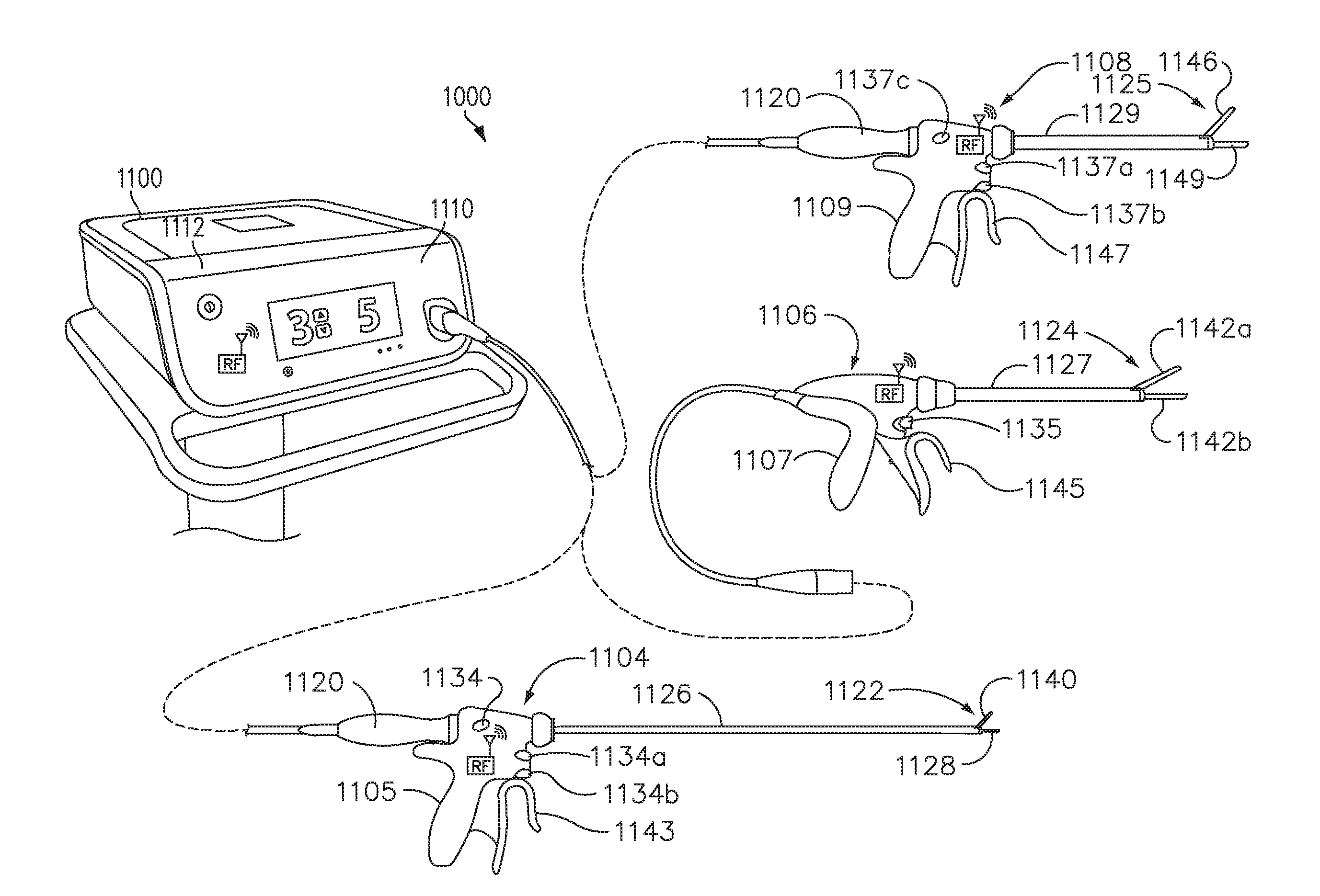
[0036] FIG. 3 is a surgical system comprising a generator and various surgical instruments usable therewith, in accordance with at least one aspect of the present disclosure.
[0037] FIG. 4 is an end effector, in accordance with at least one aspect of the present disclosure.
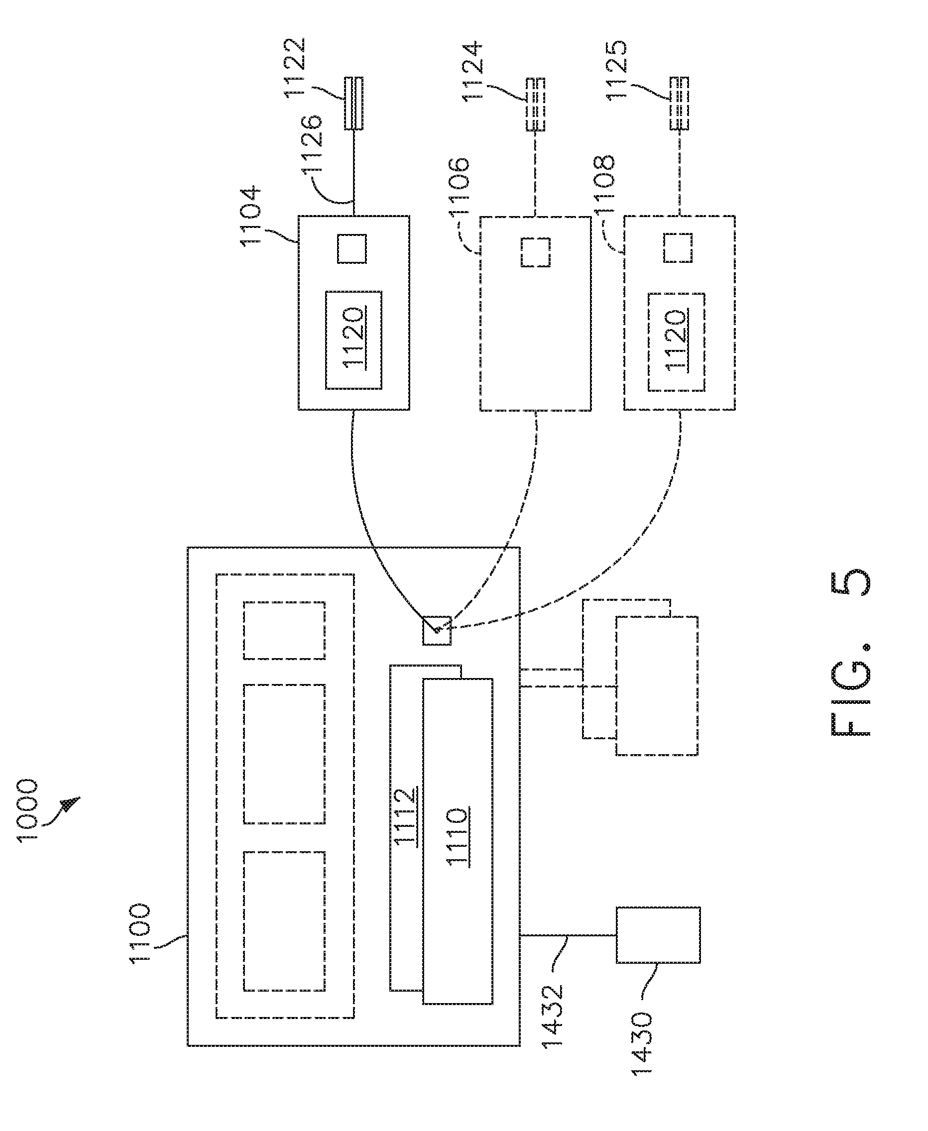
[0038] FIG. 5 is a diagram of the surgical system of FIG. 3, in accordance with at least one aspect of the present disclosure.
[0039] FIG. 6 is a model illustrating motional branch current, in accordance with at least one aspect of the present disclosure.
[0040] FIG. 7 is a structural view of a generator architecture, in accordance with at least one aspect of the present disclosure.
[0041] FIGS. 8A-8C are functional views of a generator architecture, in accordance with at least one aspect of the present disclosure.
[0042] FIGS. 9A-9B are structural and functional aspects of a generator, in accordance with at least one aspect of the present disclosure.
[0043] FIG. 10 illustrates a control circuit configured to control aspects of the surgical instrument or tool, in accordance with at least one aspect of the present disclosure.
[0044] FIG. 11 illustrates a combinational logic circuit configured to control aspects of the surgical instrument or tool, in accordance with at least one aspect of the present disclosure.
[0045] FIG. 12 illustrates a sequential logic circuit configured to control aspects of the surgical instrument or tool, in accordance with at least one aspect of the present disclosure.
[0046] FIG. 13 illustrates one aspect of a fundamental architecture for a digital synthesis circuit such as a direct digital synthesis (DDS) circuit configured to generate a plurality of wave shapes for the electrical signal waveform for use in a surgical instrument, in accordance with at least one aspect of the present disclosure.
[0047] FIG. 14 illustrates one aspect of direct digital synthesis (DDS) circuit configured to generate a plurality of wave shapes for the electrical signal waveform for use in surgical instrument, in accordance with at least one aspect of the present disclosure.
[0048] FIG. 15 illustrates one cycle of a discrete time digital electrical signal waveform, in accordance with at least one aspect of the present disclosure of an analog waveform (shown superimposed over a discrete time digital electrical signal waveform for comparison purposes), in accordance with at least one aspect of the present disclosure.
[0049] FIG. 16 is a diagram of a control system in accordance with one aspect of this disclosure.
[0050] FIG. 17 illustrates a proportional-integral-derivative (PID) controller feedback control system in accordance with one aspect of this disclosure.
[0051] FIG. 18 is an alternative system for controlling the frequency of an ultrasonic electromechanical system and detecting the impedance thereof, in accordance with at least one aspect of the present disclosure.
[0052] FIGS. 19A-19B are complex impedance spectra of the same ultrasonic device with a cold and hot ultrasonic blade, in accordance with at least one aspect of the present disclosure, where
[0053] FIG. 19A is a graphical representation of impedance phase angle as a function of resonant frequency of the same ultrasonic device with a cold (solid line) and hot (broken line) ultrasonic blade; and
[0054] FIG. 19B is a graphical representation of impedance magnitude as a function of resonant frequency of the same ultrasonic device with a cold (solid line) and hot (broken line) ultrasonic blade.
[0055] FIG. 20 is a diagram of a Kalman filter to improve temperature estimator and state space model based on impedance across an ultrasonic transducer measured at a variety of frequencies, in accordance with at least one aspect of the present disclosure.
[0056] FIG. 21 are three probability distributions employed by a state estimator of the Kalman filter shown in FIG. 20 to maximize estimates, in accordance with at least one aspect of the present disclosure.
[0057] FIG. 22A is a graphical representation of temperature versus time of an ultrasonic device with no temperature control reaching a maximum temperature of 490.degree. C.
[0058] FIG. 22B is a graphical representation of temperature versus time of an ultrasonic device with temperature control reaching a maximum temperature of 320.degree. C., in accordance with at least one aspect of the present disclosure.
[0059] FIG. 23 is a graphical representation of the relationship between initial frequency and the change in frequency required to achieve a temperature of approximately 340.degree. C., in accordance with at least one aspect of the present disclosure.
[0060] FIG. 24 illustrates a feedback control system comprising an ultrasonic generator to regulate the electrical current (i) set point applied to an ultrasonic transducer of an ultrasonic electromechanical system to prevent the frequency (f) of the ultrasonic transducer from decreasing lower than a predetermined threshold, in accordance with at least one aspect of the present disclosure.
[0061] FIG. 25 is a logic flow diagram of a process depicting a control program or a logic configuration of a controlled thermal management process to protect an end effector pad, in accordance with at least one aspect of the present disclosure.
[0062] FIG. 26 is a graphical representation of temperature versus time comparing the desired temperature of an ultrasonic blade with a smart ultrasonic blade and a conventional ultrasonic blade, in accordance with at least one aspect of the present disclosure.
[0063] FIG. 27 is a logic flow diagram of a process depicting a control program or a logic configuration to determine the initial temperature of an ultrasonic blade, in accordance with at least one aspect of the present disclosure.
DESCRIPTION
[0064] Applicant of the present patent application also owns the following contemporaneously-filed U.S. patent applications, each of which is herein incorporated by reference in its entirety: [0065] U.S. Provisional Patent Application titled METHODS FOR CONTROLLING TEMPERATURE IN ULTRASONIC DEVICE, Attorney Docket No. END8560USNP1/180106-1M; [0066] U.S. Provisional Patent Application titled ULTRASONIC SEALING ALGORITHM WITH TEMPERATURE CONTROL, Attorney Docket No. END8560USNP3/180106-3; [0067] U.S. Provisional Patent Application titled APPLICATION OF SMART ULTRASONIC BLADE TECHNOLOGY, Attorney Docket No. END8560USNP4/180106-4; [0068] U.S. Provisional Patent Application titled ADAPTIVE ADVANCED TISSUE TREATMENT PAD SAVER MODE, Attorney Docket No. END8560USNP5/180106-5; and [0069] U.S. Provisional Patent Application titled SMART BLADE TECHNOLOGY TO CONTROL BLADE INSTABILITY, Attorney Docket No. END8560USNP6/180106-6.
[0070] Applicant of the present patent application also owns the following contemporaneously-filed U.S. patent applications, each of which is herein incorporated by reference in its entirety: [0071] U.S. Provisional Patent Application titled METHODS FOR ESTIMATING AND CONTROLLING STATE OF ULTRASONIC END EFFECTOR, Attorney Docket No. END8536USNP1/180107-1M; [0072] U.S. Provisional Patent Application titled IN-THE-JAW CLASSIFIER BASED ON MODEL, Attorney Docket No. END8536USNP3/180107-3; [0073] U.S. Provisional Patent Application titled APPLICATION OF SMART BLADE TECHNOLOGY, Attorney Docket No. END8536USNP4/180107-4; [0074] U.S. Provisional Patent Application titled SMART BLADE AND POWER PULSING, Attorney Docket No. END8536USNP5/180107-5; [0075] U.S. Provisional Patent Application titled ADJUSTMENT OF COMPLEX IMPEDANCE TO COMPENSATE FOR LOST POWER IN AN ARTICULATING ULTRASONIC DEVICE, Attorney Docket No. END8536USNP6/180107-6; [0076] U.S. Provisional Patent Application titled USING SPECTROSCOPY TO DETERMINE DEVICE USE STATE IN COMBO INSTRUMENT, Attorney Docket No. END8536USNP7/180107-7; [0077] U.S. Provisional Patent Application titled VESSEL SENSING FOR ADAPTIVE ADVANCED HEMOSTASIS, Attorney Docket No. END8536USNP8/180107-8; [0078] U.S. Provisional Patent Application titled CALCIFIED VESSEL IDENTIFICATION, Attorney Docket No. END8536USNP9/180107-9; [0079] U.S. Provisional Patent Application titled DETECTION OF LARGE VESSELS DURING PARENCHYMAL DISSECTION USING A SMART BLADE, Attorney Docket No. END8536USNP10/180107-10; [0080] U.S. Provisional Patent Application titled SMART BLADE APPLICATION FOR REUSABLE AND DISPOSABLE DEVICES, Attorney Docket No. END8536USNP11/180107-11; [0081] U.S. Provisional Patent Application titled LIVE TIME TISSUE CLASSIFICATION USING ELECTRICAL PARAMETERS, Attorney Docket No. END8536USNP12/180107-12; and [0082] U.S. Provisional Patent Application titled FINE DISSECTION MODE FOR TISSUE CLASSIFICATION, Attorney Docket No. END8536USNP13/180107-13.
[0083] Applicant of the present application owns the following U.S. Patent Applications, filed on Sep. 10, 2018, the disclosure of each of which is herein incorporated by reference in its entirety: [0084] U.S. Provisional Patent Application Ser. No. 62/729,177, titled AUTOMATED DATA SCALING, ALIGNMENT, AND ORGANIZING BASED ON PREDEFINED PARAMETERS WITHIN A SURGICAL NETWORK BEFORE TRANSMISSION; [0085] U.S. provisional Patent Application Ser. No. 62/729,182, titled SENSING THE PATIENT POSITION AND CONTACT UTILIZING THE MONO-POLAR RETURN PAD ELECTRODE TO PROVIDE SITUATIONAL AWARENESS TO THE HUB; [0086] U.S. Provisional Patent Application Ser. No. 62/729,184, titled POWERED SURGICAL TOOL WITH A PREDEFINED ADJUSTABLE CONTROL ALGORITHM FOR CONTROLLING AT LEAST ONE END-EFFECTOR PARAMETER AND A MEANS FOR LIMITING THE ADJUSTMENT; [0087] U.S. Provisional Patent Application Ser. No. 62/729,183, titled SURGICAL NETWORK RECOMMENDATIONS FROM REAL TIME ANALYSIS OF PROCEDURE VARIABLES AGAINST A BASELINE HIGHLIGHTING DIFFERENCES FROM THE OPTIMAL SOLUTION; [0088] U.S. Provisional Patent Application Ser. No. 62/729,191, titled A CONTROL FOR A SURGICAL NETWORK OR SURGICAL NETWORK CONNECTED DEVICE THAT ADJUSTS ITS FUNCTION BASED ON A SENSED SITUATION OR USAGE; [0089] U.S. Provisional Patent Application Ser. No. 62/729,176, titled INDIRECT COMMAND AND CONTROL OF A FIRST OPERATING ROOM SYSTEM THROUGH THE USE OF A SECOND OPERATING ROOM SYSTEM WITHIN A STERILE FIELD WHERE THE SECOND OPERATING ROOM SYSTEM HAS PRIMARY AND SECONDARY OPERATING MODES; [0090] U.S. Provisional Patent Application Ser. No. 62/729,186, titled WIRELESS PAIRING OF A SURGICAL DEVICE WITH ANOTHER DEVICE WITHIN A STERILE SURGICAL FIELD BASED ON THE USAGE AND SITUATIONAL AWARENESS OF DEVICES; and [0091] U.S. Provisional Patent Application Ser. No. 62/729,185, titled POWERED STAPLING DEVICE THAT IS CAPABLE OF ADJUSTING FORCE, ADVANCEMENT SPEED, AND OVERALL STROKE OF CUTTING MEMBER OF THE DEVICE BASED ON SENSED PARAMETER OF FIRING OR CLAMPING.
[0092] Applicant of the present application owns the following U.S. Patent Applications, filed on Aug. 28, 2018, the disclosure of each of which is herein incorporated by reference in its entirety: [0093] U.S. patent application Ser. No. 16/115,214, titled ESTIMATING STATE OF ULTRASONIC END EFFECTOR AND CONTROL SYSTEM THEREFOR; [0094] U.S. patent application Ser. No. 16/115,205, titled TEMPERATURE CONTROL OF ULTRASONIC END EFFECTOR AND CONTROL SYSTEM THEREFOR; [0095] U.S. patent application Ser. No. 16/115,233, titled RADIO FREQUENCY ENERGY DEVICE FOR DELIVERING COMBINED ELECTRICAL SIGNALS; [0096] U.S. patent application Ser. No. 16/115,208, titled CONTROLLING AN ULTRASONIC SURGICAL INSTRUMENT ACCORDING TO TISSUE LOCATION; [0097] U.S. patent application Ser. No. 16/115,220, titled CONTROLLING ACTIVATION OF AN ULTRASONIC SURGICAL INSTRUMENT ACCORDING TO THE PRESENCE OF TISSUE; [0098] U.S. patent application Ser. No. 16/115,232, titled DETERMINING TISSUE COMPOSITION VIA AN ULTRASONIC SYSTEM; [0099] U.S. patent application Ser. No. 16/115,239, titled DETERMINING THE STATE OF AN ULTRASONIC ELECTROMECHANICAL SYSTEM ACCORDING TO FREQUENCY SHIFT; [0100] U.S. patent application Ser. No. 16/115,247, titled DETERMINING THE STATE OF AN ULTRASONIC END EFFECTOR; [0101] U.S. patent application Ser. No. 16/115,211, titled SITUATIONAL AWARENESS OF ELECTROSURGICAL SYSTEMS; [0102] U.S. patent application Ser. No. 16/115,226, titled MECHANISMS FOR CONTROLLING DIFFERENT ELECTROMECHANICAL SYSTEMS OF AN ELECTROSURGICAL INSTRUMENT; [0103] U.S. patent application Ser. No. 16/115,240, titled DETECTION OF END EFFECTOR EMERSION IN LIQUID; [0104] U.S. patent application Ser. No. 16/115,249, titled INTERRUPTION OF ENERGY DUE TO INADVERTENT CAPACITIVE COUPLING; [0105] U.S. patent application Ser. No. 16/115,256, titled INCREASING RADIO FREQUENCY TO CREATE PAD-LESS MONOPOLAR LOOP; [0106] U.S. patent application Ser. No. 16/115,223, titled BIPOLAR COMBINATION DEVICE THAT AUTOMATICALLY ADJUSTS PRESSURE BASED ON ENERGY MODALITY; and [0107] U.S. patent application Ser. No. 16/115,238, titled ACTIVATION OF ENERGY DEVICES.
[0108] Applicant of the present application owns the following U.S. Patent Applications, filed on Aug. 23, 2018, the disclosure of each of which is herein incorporated by reference in its entirety: [0109] U.S. Provisional Patent Application No. 62/721,995, titled CONTROLLING AN ULTRASONIC SURGICAL INSTRUMENT ACCORDING TO TISSUE LOCATION; [0110] U.S. Provisional Patent Application No. 62/721,998, titled SITUATIONAL AWARENESS OF ELECTROSURGICAL SYSTEMS; [0111] U.S. Provisional Patent Application No. 62/721,999, titled INTERRUPTION OF ENERGY DUE TO INADVERTENT CAPACITIVE COUPLING; [0112] U.S. Provisional Patent Application No. 62/721,994, titled BIPOLAR COMBINATION DEVICE THAT AUTOMATICALLY ADJUSTS PRESSURE BASED ON ENERGY MODALITY; and [0113] U.S. Provisional Patent Application No. 62/721,996, titled RADIO FREQUENCY ENERGY DEVICE FOR DELIVERING COMBINED ELECTRICAL SIGNALS.
[0114] Applicant of the present application owns the following U.S. Patent Applications, filed on Jun. 30, 2018, the disclosure of each of which is herein incorporated by reference in its entirety: [0115] U.S. Provisional Patent Application No. 62/692,747, titled SMART ACTIVATION OF AN ENERGY DEVICE BY ANOTHER DEVICE; [0116] U.S. Provisional Patent Application No. 62/692,748, titled SMART ENERGY ARCHITECTURE; and [0117] U.S. Provisional Patent Application No. 62/692,768, titled SMART ENERGY DEVICES.
[0118] Applicant of the present application owns the following U.S. Patent Applications, filed on Jun. 29, 2018, the disclosure of each of which is herein incorporated by reference in its entirety: [0119] U.S. patent application Ser. No. 16/024,090, titled CAPACITIVE COUPLED RETURN PATH PAD WITH SEPARABLE ARRAY ELEMENTS; [0120] U.S. patent application Ser. No. 16/024,057, titled CONTROLLING A SURGICAL INSTRUMENT ACCORDING TO SENSED CLOSURE PARAMETERS; [0121] U.S. patent application Ser. No. 16/024,067, titled SYSTEMS FOR ADJUSTING END EFFECTOR PARAMETERS BASED ON PERIOPERATIVE INFORMATION; [0122] U.S. patent application Ser. No. 16/024,075, titled SAFETY SYSTEMS FOR SMART POWERED SURGICAL STAPLING; [0123] U.S. patent application Ser. No. 16/024,083, titled SAFETY SYSTEMS FOR SMART POWERED SURGICAL STAPLING; [0124] U.S. patent application Ser. No. 16/024,094, titled SURGICAL SYSTEMS FOR DETECTING END EFFECTOR TISSUE DISTRIBUTION IRREGULARITIES; [0125] U.S. patent application Ser. No. 16/024,138, titled SYSTEMS FOR DETECTING PROXIMITY OF SURGICAL END EFFECTOR TO CANCEROUS TISSUE; [0126] U.S. patent application Ser. No. 16/024,150, titled SURGICAL INSTRUMENT CARTRIDGE SENSOR ASSEMBLIES; [0127] U.S. patent application Ser. No. 16/024,160, titled VARIABLE OUTPUT CARTRIDGE SENSOR ASSEMBLY; [0128] U.S. patent application Ser. No. 16/024,124, titled SURGICAL INSTRUMENT HAVING A FLEXIBLE ELECTRODE; [0129] U.S. patent application Ser. No. 16/024,132, titled SURGICAL INSTRUMENT HAVING A FLEXIBLE CIRCUIT; [0130] U.S. patent application Ser. No. 16/024,141, titled SURGICAL INSTRUMENT WITH A TISSUE MARKING ASSEMBLY; [0131] U.S. patent application Ser. No. 16/024,162, titled SURGICAL SYSTEMS WITH PRIORITIZED DATA TRANSMISSION CAPABILITIES; [0132] U.S. patent application Ser. No. 16/024,066, titled SURGICAL EVACUATION SENSING AND MOTOR CONTROL; [0133] U.S. patent application Ser. No. 16/024,096, titled SURGICAL EVACUATION SENSOR ARRANGEMENTS; [0134] U.S. patent application Ser. No. 16/024,116, titled SURGICAL EVACUATION FLOW PATHS; [0135] U.S. patent application Ser. No. 16/024,149, titled SURGICAL EVACUATION SENSING AND GENERATOR CONTROL; [0136] U.S. patent application Ser. No. 16/024,180, titled SURGICAL EVACUATION SENSING AND DISPLAY; [0137] U.S. patent application Ser. No. 16/024,245, titled COMMUNICATION OF SMOKE EVACUATION SYSTEM PARAMETERS TO HUB OR CLOUD IN SMOKE EVACUATION MODULE FOR INTERACTIVE SURGICAL PLATFORM; [0138] U.S. patent application Ser. No. 16/024,258, titled SMOKE EVACUATION SYSTEM INCLUDING A SEGMENTED CONTROL CIRCUIT FOR INTERACTIVE SURGICAL PLATFORM; [0139] U.S. patent application Ser. No. 16/024,265, titled SURGICAL EVACUATION SYSTEM WITH A COMMUNICATION CIRCUIT FOR COMMUNICATION BETWEEN A FILTER AND A SMOKE EVACUATION DEVICE; and [0140] U.S. Patent Application Ser. No. 16/024,273, titled DUAL IN-SERIES LARGE AND SMALL DROPLET FILTERS.
[0141] Applicant of the present application owns the following U.S. Provisional Patent Applications, filed on Jun. 28, 2018, the disclosure of each of which is herein incorporated by reference in its entirety: [0142] U.S. Provisional Patent Application Ser. No. 62/691,228, titled A METHOD OF USING REINFORCED FLEX CIRCUITS WITH MULTIPLE SENSORS WITH ELECTROSURGICAL DEVICES; [0143] U.S. Provisional Patent Application Ser. No. 62/691,227, titled CONTROLLING A SURGICAL INSTRUMENT ACCORDING TO SENSED CLOSURE PARAMETERS; [0144] U.S. Provisional Patent Application Ser. No. 62/691,230, titled SURGICAL INSTRUMENT HAVING A FLEXIBLE ELECTRODE; [0145] U.S. Provisional Patent Application Ser. No. 62/691,219, titled SURGICAL EVACUATION SENSING AND MOTOR CONTROL; [0146] U.S. Provisional Patent Application Ser. No. 62/691,257, titled COMMUNICATION OF SMOKE EVACUATION SYSTEM PARAMETERS TO HUB OR CLOUD IN SMOKE EVACUATION MODULE FOR INTERACTIVE SURGICAL PLATFORM; [0147] U.S. Provisional Patent Application Ser. No. 62/691,262, titled SURGICAL EVACUATION SYSTEM WITH A COMMUNICATION CIRCUIT FOR COMMUNICATION BETWEEN A FILTER AND A SMOKE EVACUATION DEVICE; and [0148] U.S. Provisional Patent Application Ser. No. 62/691,251, titled DUAL IN-SERIES LARGE AND SMALL DROPLET FILTERS.
[0149] Applicant of the present application owns the following U.S. Provisional Patent Application, filed on Apr. 19, 2018, the disclosure of each of which is herein incorporated by reference in its entirety: [0150] U.S. Provisional Patent Application Ser. No. 62/659,900, titled METHOD OF HUB COMMUNICATION.
[0151] Applicant of the present application owns the following U.S. Provisional Patent Applications, filed on Mar. 30, 2018, the disclosure of each of which is herein incorporated by reference in its entirety: [0152] U.S. Provisional Patent Application No. 62/650,898 filed on Mar. 30, 2018, titled CAPACITIVE COUPLED RETURN PATH PAD WITH SEPARABLE ARRAY ELEMENTS; [0153] U.S. Provisional Patent Application Ser. No. 62/650,887, titled SURGICAL SYSTEMS WITH OPTIMIZED SENSING CAPABILITIES; [0154] U.S. Provisional Patent Application Ser. No. 62/650,882, titled SMOKE EVACUATION MODULE FOR INTERACTIVE SURGICAL PLATFORM; and [0155] U.S. Provisional Patent Application Ser. No. 62/650,877, titled SURGICAL SMOKE EVACUATION SENSING AND CONTROLS.
[0156] Applicant of the present application owns the following U.S. Patent Applications, filed on Mar. 29, 2018, the disclosure of each of which is herein incorporated by reference in its entirety: [0157] U.S. patent application Ser. No. 15/940,641, titled INTERACTIVE SURGICAL SYSTEMS WITH ENCRYPTED COMMUNICATION CAPABILITIES; [0158] U.S. patent application Ser. No. 15/940,648, titled INTERACTIVE SURGICAL SYSTEMS WITH CONDITION HANDLING OF DEVICES AND DATA CAPABILITIES; [0159] U.S. patent application Ser. No. 15/940,656, titled SURGICAL HUB COORDINATION OF CONTROL AND COMMUNICATION OF OPERATING ROOM DEVICES; [0160] U.S. patent application Ser. No. 15/940,666, titled SPATIAL AWARENESS OF SURGICAL HUBS IN OPERATING ROOMS; [0161] U.S. patent application Ser. No. 15/940,670, titled COOPERATIVE UTILIZATION OF DATA DERIVED FROM SECONDARY SOURCES BY INTELLIGENT SURGICAL HUBS; [0162] U.S. patent application Ser. No. 15/940,677, titled SURGICAL HUB CONTROL ARRANGEMENTS; [0163] U.S. patent application Ser. No. 15/940,632, titled DATA STRIPPING METHOD TO INTERROGATE PATIENT RECORDS AND CREATE ANONYMIZED RECORD; [0164] U.S. patent application Ser. No. 15/940,640, titled COMMUNICATION HUB AND STORAGE DEVICE FOR STORING PARAMETERS AND STATUS OF A SURGICAL DEVICE TO BE SHARED WITH CLOUD BASED ANALYTICS SYSTEMS; [0165] U.S. patent application Ser. No. 15/940,645, titled SELF DESCRIBING DATA PACKETS GENERATED AT AN ISSUING INSTRUMENT; [0166] U.S. patent application Ser. No. 15/940,649, titled DATA PAIRING TO INTERCONNECT A DEVICE MEASURED PARAMETER WITH AN OUTCOME; [0167] U.S. patent application Ser. No. 15/940,654, titled SURGICAL HUB SITUATIONAL AWARENESS; [0168] U.S. patent application Ser. No. 15/940,663, titled SURGICAL SYSTEM DISTRIBUTED PROCESSING; [0169] U.S. patent application Ser. No. 15/940,668, titled AGGREGATION AND REPORTING OF SURGICAL HUB DATA; [0170] U.S. patent application Ser. No. 15/940,671, titled SURGICAL HUB SPATIAL AWARENESS TO DETERMINE DEVICES IN OPERATING THEATER; [0171] U.S. patent application Ser. No. 15/940,686, titled DISPLAY OF ALIGNMENT OF STAPLE CARTRIDGE TO PRIOR LINEAR STAPLE LINE; [0172] U.S. patent application Ser. No. 15/940,700, titled STERILE FIELD INTERACTIVE CONTROL DISPLAYS; [0173] U.S. patent application Ser. No. 15/940,629, titled COMPUTER IMPLEMENTED INTERACTIVE SURGICAL SYSTEMS; [0174] U.S. patent application Ser. No. 15/940,704, titled USE OF LASER LIGHT AND RED-GREEN-BLUE COLORATION TO DETERMINE PROPERTIES OF BACK SCATTERED LIGHT; [0175] U.S. patent application Ser. No. 15/940,722, titled CHARACTERIZATION OF TISSUE IRREGULARITIES THROUGH THE USE OF MONO-CHROMATIC LIGHT REFRACTIVITY; and [0176] U.S. patent application Ser. No. 15/940,742, titled DUAL CMOS ARRAY IMAGING. [0177] U.S. patent application Ser. No. 15/940,636, titled ADAPTIVE CONTROL PROGRAM UPDATES FOR SURGICAL DEVICES; [0178] U.S. patent application Ser. No. 15/940,653, titled ADAPTIVE CONTROL PROGRAM UPDATES FOR SURGICAL HUBS; [0179] U.S. patent application Ser. No. 15/940,660, titled CLOUD-BASED MEDICAL ANALYTICS FOR CUSTOMIZATION AND RECOMMENDATIONS TO A USER; [0180] U.S. patent application Ser. No. 15/940,679, titled CLOUD-BASED MEDICAL ANALYTICS FOR LINKING OF LOCAL USAGE TRENDS WITH THE RESOURCE ACQUISITION BEHAVIORS OF LARGER DATA SET; [0181] U.S. patent application Ser. No. 15/940,694, titled CLOUD-BASED MEDICAL ANALYTICS FOR MEDICAL FACILITY SEGMENTED INDIVIDUALIZATION OF INSTRUMENT FUNCTION; [0182] U.S. patent application Ser. No. 15/940,634, titled CLOUD-BASED MEDICAL ANALYTICS FOR SECURITY AND AUTHENTICATION TRENDS AND REACTIVE MEASURES; [0183] U.S. patent application Ser. No. 15/940,706, titled DATA HANDLING AND PRIORITIZATION IN A CLOUD ANALYTICS NETWORK; and [0184] U.S. patent application Ser. No. 15/940,675, titled CLOUD INTERFACE FOR COUPLED SURGICAL DEVICES. [0185] U.S. patent application Ser. No. 15/940,627, titled DRIVE ARRANGEMENTS FOR ROBOT-ASSISTED SURGICAL PLATFORMS; [0186] U.S. patent application Ser. No. 15/940,637, titled COMMUNICATION ARRANGEMENTS FOR ROBOT-ASSISTED SURGICAL PLATFORMS; [0187] U.S. patent application Ser. No. 15/940,642, titled CONTROLS FOR ROBOT-ASSISTED SURGICAL PLATFORMS; [0188] U.S. patent application Ser. No. 15/940,676, titled AUTOMATIC TOOL ADJUSTMENTS FOR ROBOT-ASSISTED SURGICAL PLATFORMS; [0189] U.S. patent application Ser. No. 15/940,680, titled CONTROLLERS FOR ROBOT-ASSISTED SURGICAL PLATFORMS; [0190] U.S. patent application Ser. No. 15/940,683, titled COOPERATIVE SURGICAL ACTIONS FOR ROBOT-ASSISTED SURGICAL PLATFORMS; [0191] U.S. patent application Ser. No. 15/940,690, titled DISPLAY ARRANGEMENTS FOR ROBOT-ASSISTED SURGICAL PLATFORMS; and [0192] U.S. patent application Ser. No. 15/940,711, titled SENSING ARRANGEMENTS FOR ROBOT-ASSISTED SURGICAL PLATFORMS.
[0193] Applicant of the present application owns the following U.S. Provisional Patent Applications, filed on Mar. 28, 2018, the disclosure of each of which is herein incorporated by reference in its entirety: [0194] U.S. Provisional Patent Application Ser. No. 62/649,302, titled INTERACTIVE SURGICAL SYSTEMS WITH ENCRYPTED COMMUNICATION CAPABILITIES; [0195] U.S. Provisional Patent Application Ser. No. 62/649,294, titled DATA STRIPPING METHOD TO INTERROGATE PATIENT RECORDS AND CREATE ANONYMIZED RECORD; [0196] U.S. Provisional Patent Application Ser. No. 62/649,300, titled SURGICAL HUB SITUATIONAL AWARENESS; [0197] U.S. Provisional Patent Application Ser. No. 62/649,309, titled SURGICAL HUB SPATIAL AWARENESS TO DETERMINE DEVICES IN OPERATING THEATER; [0198] U.S. Provisional Patent Application Ser. No. 62/649,310, titled COMPUTER IMPLEMENTED INTERACTIVE SURGICAL SYSTEMS; [0199] U.S. Provisional Patent Application Ser. No. 62/649,291, titled USE OF LASER LIGHT AND RED-GREEN-BLUE COLORATION TO DETERMINE PROPERTIES OF BACK SCATTERED LIGHT; [0200] U.S. Provisional Patent Application Ser. No. 62/649,296, titled ADAPTIVE CONTROL PROGRAM UPDATES FOR SURGICAL DEVICES; [0201] U.S. Provisional Patent Application Ser. No. 62/649,333, titled CLOUD-BASED MEDICAL ANALYTICS FOR CUSTOMIZATION AND RECOMMENDATIONS TO A USER; [0202] U.S. Provisional Patent Application Ser. No. 62/649,327, titled CLOUD-BASED MEDICAL ANALYTICS FOR SECURITY AND AUTHENTICATION TRENDS AND REACTIVE MEASURES; [0203] U.S. Provisional Patent Application Ser. No. 62/649,315, titled DATA HANDLING AND PRIORITIZATION IN A CLOUD ANALYTICS NETWORK; [0204] U.S. Provisional Patent Application Ser. No. 62/649,313, titled CLOUD INTERFACE FOR COUPLED SURGICAL DEVICES; [0205] U.S. Provisional Patent Application Ser. No. 62/649,320, titled DRIVE ARRANGEMENTS FOR ROBOT-ASSISTED SURGICAL PLATFORMS; [0206] U.S. Provisional Patent Application Ser. No. 62/649,307, titled AUTOMATIC TOOL ADJUSTMENTS FOR ROBOT-ASSISTED SURGICAL PLATFORMS; and [0207] U.S. Provisional Patent Application Ser. No. 62/649,323, titled SENSING ARRANGEMENTS FOR ROBOT-ASSISTED SURGICAL PLATFORMS. Applicant of the present application owns the following U.S. Provisional Patent
[0208] Applications, filed on Dec. 28, 2017, the disclosure of each of which is herein incorporated by reference in its entirety: [0209] U.S. Provisional Patent Application Ser. No. U.S. Provisional Patent Application Serial No. 62/611,341, titled INTERACTIVE SURGICAL PLATFORM; [0210] U.S. Provisional Patent Application Ser. No. 62/611,340, titled CLOUD-BASED MEDICAL ANALYTICS; and [0211] U.S. Provisional Patent Application Ser. No. 62/611,339, titled ROBOT ASSISTED SURGICAL PLATFORM.
[0212] Before explaining various aspects of surgical devices and generators in detail, it should be noted that the illustrative examples are not limited in application or use to the details of construction and arrangement of parts illustrated in the accompanying drawings and description. The illustrative examples may be implemented or incorporated in other aspects, variations and modifications, and may be practiced or carried out in various ways. Further, unless otherwise indicated, the terms and expressions employed herein have been chosen for the purpose of describing the illustrative examples for the convenience of the reader and are not for the purpose of limitation thereof. Also, it will be appreciated that one or more of the following-described aspects, expressions of aspects, and/or examples, can be combined with any one or more of the other following-described aspects, expressions of aspects and/or examples. Various aspects are directed to improved ultrasonic surgical devices, electrosurgical devices and generators for use therewith. Aspects of the ultrasonic surgical devices can be configured for transecting and/or coagulating tissue during surgical procedures, for example. Aspects of the electrosurgical devices can be configured for transecting, coagulating, scaling, welding and/or desiccating tissue during surgical procedures, for example.
Adaptive Ultrasonic Blade Control Algorithms
[0213] In various aspects smart ultrasonic energy devices may comprise adaptive algorithms to control the operation of the ultrasonic blade. In one aspect, the ultrasonic blade adaptive control algorithms are configured to identify tissue type and adjust device parameters. In one aspect, the ultrasonic blade control algorithms are configured to parameterize tissue type. An algorithm to detect the collagen/elastic ratio of tissue to tune the amplitude of the distal tip of the ultrasonic blade is described in the following section of the present disclosure. Various aspects of smart ultrasonic energy devices are described herein in connection with FIGS. 1-2, for example. Accordingly, the following description of adaptive ultrasonic blade control algorithms should be read in conjunction with FIGS. 1-2 and the description associated therewith.
[0214] In certain surgical procedures it would be desirable to employ adaptive ultrasonic blade control algorithms. In one aspect, adaptive ultrasonic blade control algorithms may be employed to adjust the parameters of the ultrasonic device based on the type of tissue in contact with the ultrasonic blade. In one aspect, the parameters of the ultrasonic device may be adjusted based on the location of the tissue within the jaws of the ultrasonic end effector, for example, the location of the tissue between the clamp arm and the ultrasonic blade. The impedance of the ultrasonic transducer may be employed to differentiate what percentage of the tissue is located in the distal or proximal end of the end effector. The reactions of the ultrasonic device may be based on the tissue type or compressibility of the tissue. In another aspect, the parameters of the ultrasonic device may be adjusted based on the identified tissue type or parameterization. For example, the mechanical displacement amplitude of the distal tip of the ultrasonic blade may be tuned based on the ration of collagen to elastin tissue detected during the tissue identification procedure. The ratio of collagen to elastin tissue may be detected used a variety of techniques including infrared (IR) surface reflectance and emissivity. The force applied to the tissue by the clamp arm and/or the stroke of the clamp arm to produce gap and compression. Electrical continuity across a jaw equipped with electrodes may be employed to determine what percentage of the jaw is covered with tissue.
[0215] FIG. 1 is a system 800 configured to execute adaptive ultrasonic blade control algorithms in a surgical data network comprising a modular communication hub, in accordance with at least one aspect of the present disclosure. In one aspect, the generator module 240 is configured to execute the adaptive ultrasonic blade control algorithm(s) 802 as described herein. In another aspect, the device/instrument 235 is configured to execute the adaptive ultrasonic blade control algorithm(s) 804 as described herein with reference to FIGS. 25-34. In another aspect, both the device/instrument 235 and the device/instrument 235 are configured to execute the adaptive ultrasonic blade control algorithms 802, 804 as described herein with reference to FIGS.13-18.
[0216] The generator module 240 may comprise a patient isolated stage in communication with a non-isolated stage via a power transformer. A secondary winding of the power transformer is contained in the isolated stage and may comprise a tapped configuration (e.g., a center-tapped or a non-center-tapped configuration) to define drive signal outputs for delivering drive signals to different surgical instruments, such as, for example, an ultrasonic surgical instrument, an RF electrosurgical instrument, and a multifunction surgical instrument which includes ultrasonic and RF energy modes that can be delivered alone or simultaneously. In particular, the drive signal outputs may output an ultrasonic drive signal (e.g., a 420V root-mean-square (RMS) drive signal) to an ultrasonic surgical instrument 241, and the drive signal outputs may output an RF electrosurgical drive signal (e.g., a 100V RMS drive signal) to an RF electrosurgical instrument 241. Aspects of the generator module 240 are described herein with reference to FIGS. 7-12.
[0217] The generator module 240 or the device/instrument 235 or both are coupled to the modular control tower 236 connected to multiple operating theater devices such as, for example, intelligent surgical instruments, robots, and other computerized devices located in the operating theater. In some aspects, a surgical data network may include a modular communication hub configured to connect modular devices located in one or more operating theaters of a healthcare facility, or any room in a healthcare facility specially equipped for surgical operations, to a cloud-based system (e.g., the cloud 204 that may include a remote server 213 coupled to a storage device).
[0218] Modular devices located in the operating theater may be coupled to the modular communication hub. The network hub and/or the network switch may be coupled to a network router to connect the devices to the cloud 204 or a local computer system. Data associated with the devices may be transferred to cloud-based computers via the router for remote data processing and manipulation. Data associated with the devices may also be transferred to a local computer system for local data processing and manipulation. Modular devices located in the same operating theater also may be coupled to a network switch. The network switch may be coupled to the network hub and/or the network router to connect to the devices to the cloud 204. Data associated with the devices may be transferred to the cloud 204 via the network router for data processing and manipulation. Data associated with the devices may also be transferred to the local computer system for local data processing and manipulation.
[0219] It will be appreciated that cloud computing relies on sharing computing resources rather than having local servers or personal devices to handle software applications. The word "cloud" may be used as a metaphor for "the Internet," although the term is not limited as such. Accordingly, the term "cloud computing" may be used herein to refer to "a type of Internet-based computing," where different services--such as servers, storage, and applications--are delivered to the modular communication hub and/or computer system located in the surgical theater (e.g., a fixed, mobile, temporary, or field operating room or space) and to devices connected to the modular communication hub and/or computer system through the Internet. The cloud infrastructure may be maintained by a cloud service provider. In this context, the cloud service provider may be the entity that coordinates the usage and control of the devices located in one or more operating theaters. The cloud computing services can perform a large number of calculations based on the data gathered by smart surgical instruments, robots, and other computerized devices located in the operating theater. The hub hardware enables multiple devices or connections to be connected to a computer that communicates with the cloud computing resources and storage.
[0220] FIG. 1 further illustrates some aspects of a computer-implemented interactive surgical system comprising a modular communication hub that may include the system 800 configured to execute adaptive ultrasonic blade control algorithms in a surgical data network. The surgical system may include at least one surgical hub in communication with a cloud 204 that may include a remote server 213. In one aspect, the computer-implemented interactive surgical system comprises a modular control tower 236 connected to multiple operating theater devices such as, for example, intelligent surgical instruments, robots, and other computerized devices located in the operating theater. The modular control tower 236 may comprise a modular communication hub coupled to a computer system. In some aspects, the modular control tower 236 is coupled to an imaging module that is coupled to an endoscope, a generator module 240 that is coupled to an energy device 241, and a smart device/instrument 235 optionally coupled to a display 237. The operating theater devices are coupled to cloud computing resources and data storage via the modular control tower 236. A robot hub 222 also may be connected to the modular control tower 236 and to the cloud computing resources. The devices/instruments 235, visualization systems 208, among others, may be coupled to the modular control tower 236 via wired or wireless communication standards or protocols, as described herein. The modular control tower 236 may be coupled to a hub display 215 (e.g., monitor, screen) to display and overlay images received from the imaging module, device/instrument display, and/or other visualization systems 208. The hub display 215 also may display data received from devices connected to the modular control tower in conjunction with images and overlaid images.
Generator Hardware
[0221] FIG. 2 illustrates an example of a generator 900, which is one form of a generator configured to couple to an ultrasonic instrument and further configured to execute adaptive ultrasonic blade control algorithms in a surgical data network comprising a modular communication hub as shown in FIG. 1. The generator 900 is configured to deliver multiple energy modalities to a surgical instrument. The generator 900 provides RF and ultrasonic signals for delivering energy to a surgical instrument either independently or simultaneously. The RF and ultrasonic signals may be provided alone or in combination and may be provided simultaneously. As noted above, at least one generator output can deliver multiple energy modalities (e.g., ultrasonic, bipolar or monopolar RF, irreversible and/or reversible electroporation, and/or microwave energy, among others) through a single port, and these signals can be delivered separately or simultaneously to the end effector to treat tissue. The generator 900 comprises a processor 902 coupled to a waveform generator 904. The processor 902 and waveform generator 904 are configured to generate a variety of signal waveforms based on information stored in a memory coupled to the processor 902, not shown for clarity of disclosure. The digital information associated with a waveform is provided to the waveform generator 904 which includes one or more DAC circuits to convert the digital input into an analog output. The analog output is fed to an amplifier 906 for signal conditioning and amplification. The conditioned and amplified output of the amplifier 906 is coupled to a power transformer 908. The signals are coupled across the power transformer 908 to the secondary side, which is in the patient isolation side. A first signal of a first energy modality is provided to the surgical instrument between the terminals labeled ENERGY.sub.1 and RETURN. A second signal of a second energy modality is coupled across a capacitor 910 and is provided to the surgical instrument between the terminals labeled ENERGY.sub.2 and RETURN. It will be appreciated that more than two energy modalities may be output and thus the subscript "n" may be used to designate that up to n ENERGY.sub.n terminals may be provided, where n is a positive integer greater than 1. It also will be appreciated that up to "n" return paths RETURN.sub.n may be provided without departing from the scope of the present disclosure.
[0222] A first voltage sensing circuit 912 is coupled across the terminals labeled ENERGY.sub.1 and the RETURN path to measure the output voltage therebetween. A second voltage sensing circuit 924 is coupled across the terminals labeled ENERGY.sub.2 and the RETURN path to measure the output voltage therebetween. A current sensing circuit 914 is disposed in series with the RETURN leg of the secondary side of the power transformer 908 as shown to measure the output current for either energy modality. If different return paths are provided for each energy modality, then a separate current sensing circuit should be provided in each return leg. The outputs of the first and second voltage sensing circuits 912, 924 are provided to respective isolation transformers 916, 922 and the output of the current sensing circuit 914 is provided to another isolation transformer 918. The outputs of the isolation transformers 916, 928, 922 in the on the primary side of the power transformer 908 (non-patient isolated side) are provided to a one or more ADC circuit 926. The digitized output of the ADC circuit 926 is provided to the processor 902 for further processing and computation. The output voltages and output current feedback information can be employed to adjust the output voltage and current provided to the surgical instrument and to compute output impedance, among other parameters. Input/output communications between the processor 902 and patient isolated circuits is provided through an interface circuit 920. Sensors also may be in electrical communication with the processor 902 by way of the interface circuit 920.
[0223] In one aspect, the impedance may be determined by the processor 902 by dividing the output of either the first voltage sensing circuit 912 coupled across the terminals labeled ENERGY.sub.i/RETURN or the second voltage sensing circuit 924 coupled across the terminals labeled ENERGY.sub.2/RETURN by the output of the current sensing circuit 914 disposed in series with the RETURN leg of the secondary side of the power transformer 908. The outputs of the first and second voltage sensing circuits 912, 924 are provided to separate isolations transformers 916, 922 and the output of the current sensing circuit 914 is provided to another isolation transformer 916. The digitized voltage and current sensing measurements from the ADC circuit 926 are provided the processor 902 for computing impedance. As an example, the first energy modality ENERGY.sub.1 may be ultrasonic energy and the second energy modality ENERGY.sub.2 may be RF energy. Nevertheless, in addition to ultrasonic and bipolar or monopolar RF energy modalities, other energy modalities include irreversible and/or reversible electroporation and/or microwave energy, among others. Also, although the example illustrated in FIG. 2 shows a single return path RETURN may be provided for two or more energy modalities, in other aspects, multiple return paths RETURN.sub.n may be provided for each energy modality ENERGY.sub.n. Thus, as described herein, the ultrasonic transducer impedance may be measured by dividing the output of the first voltage sensing circuit 912 by the current sensing circuit 914 and the tissue impedance may be measured by dividing the output of the second voltage sensing circuit 924 by the current sensing circuit 914.
[0224] As shown in FIG. 2, the generator 900 comprising at least one output port can include a power transformer 908 with a single output and with multiple taps to provide power in the form of one or more energy modalities, such as ultrasonic, bipolar or monopolar RF, irreversible and/or reversible electroporation, and/or microwave energy, among others, for example, to the end effector depending on the type of treatment of tissue being performed. For example, the generator 900 can deliver energy with higher voltage and lower current to drive an ultrasonic transducer, with lower voltage and higher current to drive RF electrodes for sealing tissue, or with a coagulation waveform for spot coagulation using either monopolar or bipolar RF electrosurgical electrodes. The output waveform from the generator 900 can be steered, switched, or filtered to provide the frequency to the end effector of the surgical instrument. The connection of an ultrasonic transducer to the generator 900 output would be preferably located between the output labeled ENERGY.sub.1 and RETURN as shown in FIG. 2. In one example, a connection of RF bipolar electrodes to the generator 900 output would be preferably located between the output labeled ENERGY.sub.2 and RETURN. In the case of monopolar output, the preferred connections would be active electrode (e.g., pencil or other probe) to the ENERGY.sub.2 output and a suitable return pad connected to the RETURN output.
[0225] Additional details are disclosed in U.S. Patent Application Publication No. 2017/0086914, titled TECHNIQUES FOR OPERATING GENERATOR FOR DIGITALLY GENERATING ELECTRICAL SIGNAL WAVEFORMS AND SURGICAL INSTRUMENTS, which published on Mar. 30, 2017, which is herein incorporated by reference in its entirety.
[0226] As used throughout this description, the term "wireless" and its derivatives may be used to describe circuits, devices, systems, methods, techniques, communications channels, etc., that may communicate data through the use of modulated electromagnetic radiation through a non-solid medium. The term does not imply that the associated devices do not contain any wires, although in some aspects they might not. The communication module may implement any of a number of wireless or wired communication standards or protocols, including but not limited to W-Fi (IEEE 802.11 family), WiMAX (IEEE 802.16 family), IEEE 802.20, long term evolution (LTE), Ev-DO, HSPA+, HSDPA+, HSUPA+, EDGE, GSM, GPRS, CDMA, TDMA, DECT, Bluetooth, Ethernet derivatives thereof, as well as any other wireless and wired protocols that are designated as 3G, 4G, 5G, and beyond. The computing module may include a plurality of communication modules. For instance, a first communication module may be dedicated to shorter range wireless communications such as Wi-Fi and Bluetooth and a second communication module may be dedicated to longer range wireless communications such as GPS, EDGE, GPRS, CDMA, WiMAX, LTE, Ev-DO, and others.
[0227] As used herein a processor or processing unit is an electronic circuit which performs operations on some external data source, usually memory or some other data stream. The term is used herein to refer to the central processor (central processing unit) in a system or computer systems (especially systems on a chip (SoCs)) that combine a number of specialized "processors."
[0228] As used herein, a system on a chip or system on chip (SoC or SOC) is an integrated circuit (also known as an "IC" or "chip") that integrates all components of a computer or other electronic systems. It may contain digital, analog, mixed-signal, and often radio-frequency functions--all on a single substrate. A SoC integrates a microcontroller (or microprocessor) with advanced peripherals like graphics processing unit (GPU), Wi-Fi module, or coprocessor. A SoC may or may not contain built-in memory.
[0229] As used herein, a microcontroller or controller is a system that integrates a microprocessor with peripheral circuits and memory. A microcontroller (or MCU for microcontroller unit) may be implemented as a small computer on a single integrated circuit. It may be similar to a SoC; an SoC may include a microcontroller as one of its components. A microcontroller may contain one or more core processing units (CPUs) along with memory and programmable input/output peripherals. Program memory in the form of Ferroelectric RAM, NOR flash or OTP ROM is also often included on chip, as well as a small amount of RAM. Microcontrollers may be employed for embedded applications, in contrast to the microprocessors used in personal computers or other general purpose applications consisting of various discrete chips.
[0230] As used herein, the term controller or microcontroller may be a stand-alone IC or chip device that interfaces with a peripheral device. This may be a link between two parts of a computer or a controller on an external device that manages the operation of (and connection with) that device.
[0231] Any of the processors or microcontrollers described herein, may be implemented by any single core or multicore processor such as those known under the trade name ARM Cortex by Texas Instruments. In one aspect, the processor may be an LM4F230H5QR ARM Cortex-M4F Processor Core, available from Texas Instruments, for example, comprising on-chip memory of 256 KB single-cycle flash memory, or other non-volatile memory, up to 40 MHz, a prefetch buffer to improve performance above 40 MHz, a 32 KB single-cycle serial random access memory (SRAM), internal read-only memory (ROM) loaded with StellarisWare.RTM. software, 2 KB electrically erasable programmable read-only memory (EEPROM), one or more pulse width modulation (PWM) modules, one or more quadrature encoder inputs (QEI) analog, one or more 12-bit Analog-to-Digital Converters (ADC) with 12 analog input channels, details of which are available for the product datasheet.
[0232] In one aspect, the processor may comprise a safety controller comprising two controller-based families such as TMS570 and RM4.times. known under the trade name Hercules ARM Cortex R4, also by Texas Instruments. The safety controller may be configured specifically for IEC 61508 and ISO 26262 safety critical applications, among others, to provide advanced integrated safety features while delivering scalable performance, connectivity, and memory options.
[0233] Modular devices include the modules (as described in connection with FIG. 3, for example) that are receivable within a surgical hub and the surgical devices or instruments that can be connected to the various modules in order to connect or pair with the corresponding surgical hub. The modular devices include, for example, intelligent surgical instruments, medical imaging devices, suction/irrigation devices, smoke evacuators, energy generators, ventilators, insufflators, and displays. The modular devices described herein can be controlled by control algorithms. The control algorithms can be executed on the modular device itself, on the surgical hub to which the particular modular device is paired, or on both the modular device and the surgical hub (e.g., via a distributed computing architecture). In some exemplifications, the modular devices' control algorithms control the devices based on data sensed by the modular device itself (i.e., by sensors in, on, or connected to the modular device). This data can be related to the patient being operated on (e.g., tissue properties or insufflation pressure) or the modular device itself (e.g., the rate at which a knife is being advanced, motor current, or energy levels). For example, a control algorithm for a surgical stapling and cutting instrument can control the rate at which the instrument's motor drives its knife through tissue according to resistance encountered by the knife as it advances.
[0234] FIG. 3 illustrates one form of a surgical system 1000 comprising a generator 1100 and various surgical instruments 1104, 1106, 1108 usable therewith, where the surgical instrument 1104 is an ultrasonic surgical instrument, the surgical instrument 1106 is an RF electrosurgical instrument, and the multifunction surgical instrument 1108 is a combination ultrasonic/RF electrosurgical instrument. The generator 1100 is configurable for use with a variety of surgical instruments. According to various forms, the generator 1100 may be configurable for use with different surgical instruments of different types including, for example, ultrasonic surgical instruments 1104, RF electrosurgical instruments 1106, and multifunction surgical instruments 1108 that integrate RF and ultrasonic energies delivered simultaneously from the generator 1100. Although in the form of FIG. 3 the generator 1100 is shown separate from the surgical instruments 1104, 1106, 1108 in one form, the generator 1100 may be formed integrally with any of the surgical instruments 1104, 1106, 1108 to form a unitary surgical system. The generator 1100 comprises an input device 1110 located on a front panel of the generator 1100 console. The input device 1110 may comprise any suitable device that generates signals suitable for programming the operation of the generator 1100. The generator 1100 may be configured for wired or wireless communication.
[0235] The generator 1100 is configured to drive multiple surgical instruments 1104, 1106, 1108. The first surgical instrument is an ultrasonic surgical instrument 1104 and comprises a handpiece 1105 (HP), an ultrasonic transducer 1120, a shaft 1126, and an end effector 1122. The end effector 1122 comprises an ultrasonic blade 1128 acoustically coupled to the ultrasonic transducer 1120 and a clamp arm 1140. The handpiece 1105 comprises a trigger 1143 to operate the clamp arm 1140 and a combination of the toggle buttons 1134a, 1134b, 1134c to energize and drive the ultrasonic blade 1128 or other function. The toggle buttons 1134a, 1134b, 1134c can be configured to energize the ultrasonic transducer 1120 with the generator 1100.
[0236] The generator 1100 also is configured to drive a second surgical instrument 1106. The second surgical instrument 1106 is an RF electrosurgical instrument and comprises a handpiece 1107 (HP), a shaft 1127, and an end effector 1124. The end effector 1124 comprises electrodes in clamp arms 1142a, 1142b and return through an electrical conductor portion of the shaft 1127. The electrodes are coupled to and energized by a bipolar energy source within the generator 1100. The handpiece 1107 comprises a trigger 1145 to operate the clamp arms 1142a, 1142b and an energy button 1135 to actuate an energy switch to energize the electrodes in the end effector 1124.
[0237] The generator 1100 also is configured to drive a multifunction surgical instrument 1108. The multifunction surgical instrument 1108 comprises a handpiece 1109 (HP), a shaft 1129, and an end effector 1125. The end effector 1125 comprises an ultrasonic blade 1149 and a clamp arm 1146. The ultrasonic blade 1149 is acoustically coupled to the ultrasonic transducer 1120. The handpiece 1109 comprises a trigger 1147 to operate the clamp arm 1146 and a combination of the toggle buttons 1137a, 1137b, 1137c to energize and drive the ultrasonic blade 1149 or other function. The toggle buttons 1137a, 1137b, 1137c can be configured to energize the ultrasonic transducer 1120 with the generator 1100 and energize the ultrasonic blade 1149 with a bipolar energy source also contained within the generator 1100.
[0238] The generator 1100 is configurable for use with a variety of surgical instruments. According to various forms, the generator 1100 may be configurable for use with different surgical instruments of different types including, for example, the ultrasonic surgical instrument 1104, the RF electrosurgical instrument 1106, and the multifunction surgical instrument 1108 that integrates RF and ultrasonic energies delivered simultaneously from the generator 1100. Although in the form of FIG. 3 the generator 1100 is shown separate from the surgical instruments 1104, 1106, 1108, in another form the generator 1100 may be formed integrally with any one of the surgical instruments 1104, 1106, 1108 to form a unitary surgical system. As discussed above, the generator 1100 comprises an input device 1110 located on a front panel of the generator 1100 console. The input device 1110 may comprise any suitable device that generates signals suitable for programming the operation of the generator 1100. The generator 1100 also may comprise one or more output devices 1112. Further aspects of generators for digitally generating electrical signal waveforms and surgical instruments are described in US patent publication US-2017-0086914-A1, which is herein incorporated by reference in its entirety.
[0239] FIG. 4 is an end effector 1122 of the example ultrasonic device 1104, in accordance with at least one aspect of the present disclosure. The end effector 1122 may comprise a blade 1128 that may be coupled to the ultrasonic transducer 1120 via a wave guide. When driven by the ultrasonic transducer 1120, the blade 1128 may vibrate and, when brought into contact with tissue, may cut and/or coagulate the tissue, as described herein. According to various aspects, and as illustrated in FIG. 4, the end effector 1122 may also comprise a clamp arm 1140 that may be configured for cooperative action with the blade 1128 of the end effector 1122. With the blade 1128, the clamp arm 1140 may comprise a set of jaws. The clamp arm 1140 may be pivotally connected at a distal end of a shaft 1126 of the instrument portion 1104. The clamp arm 1140 may include a clamp arm tissue pad 1163, which may be formed from TEFLON.RTM. or other suitable low-friction material. The pad 1163 may be mounted for cooperation with the blade 1128, with pivotal movement of the clamp arm 1140 positioning the clamp pad 1163 in substantially parallel relationship to, and in contact with, the blade 1128. By this construction, a tissue bite to be clamped may be grasped between the tissue pad 1163 and the blade 1128. The tissue pad 1163 may be provided with a sawtooth-like configuration including a plurality of axially spaced, proximally extending gripping teeth 1161 to enhance the gripping of tissue in cooperation with the blade 1128. The clamp arm 1140 may transition from the open position shown in FIG. 4 to a closed position (with the clamp arm 1140 in contact with or proximity to the blade 1128) in any suitable manner. For example, the handpiece 1105 may comprise a jaw closure trigger. When actuated by a clinician, the jaw closure trigger may pivot the clamp arm 1140 in any suitable manner.
[0240] The generator 1100 may be activated to provide the drive signal to the ultrasonic transducer 1120 in any suitable manner. For example, the generator 1100 may comprise a foot switch 1430 (FIG. 5) coupled to the generator 1100 via a footswitch cable 1432. A clinician may activate the ultrasonic transducer 1120, and thereby the ultrasonic transducer 1120 and blade 1128, by depressing the foot switch 1430. In addition, or instead of the foot switch 1430, some aspects of the device 1104 may utilize one or more switches positioned on the handpiece 1105 that, when activated, may cause the generator 1100 to activate the ultrasonic transducer 1120. In one aspect, for example, the one or more switches may comprise a pair of toggle buttons 1134, 1134a, 1134b (FIG. 3), for example, to determine an operating mode of the device 1104. When the toggle button 1134a is depressed, for example, the ultrasonic generator 1100 may provide a maximum drive signal to the ultrasonic transducer 1120, causing it to produce maximum ultrasonic energy output. Depressing toggle button 1134b may cause the ultrasonic generator 1100 to provide a user-selectable drive signal to the ultrasonic transducer 1120, causing it to produce less than the maximum ultrasonic energy output. The device 1104 additionally or alternatively may comprise a second switch to, for example, indicate a position of a jaw closure trigger for operating the jaws via the clamp arm 1140 of the end effector 1122. Also, in some aspects, the ultrasonic generator 1100 may be activated based on the position of the jaw closure trigger, (e.g., as the clinician depresses the jaw closure trigger to close the jaws via the clamp arm 1140, ultrasonic energy may be applied).
[0241] Additionally or alternatively, the one or more switches may comprise a toggle button 1134 that, when depressed, causes the generator 1100 to provide a pulsed output (FIG. 3). The pulses may be provided at any suitable frequency and grouping, for example. In certain aspects, the power level of the pulses may be the power levels associated with toggle buttons 1134a, 1134b (maximum, less than maximum), for example.
[0242] It will be appreciated that a device 1104 may comprise any combination of the toggle buttons 1134a, 1134b, 1134 (FIG. 3). For example, the device 1104 could be configured to have only two toggle buttons: a toggle button 1134a for producing maximum ultrasonic energy output and a toggle button 1134 for producing a pulsed output at either the maximum or less than maximum power level per. In this way, the drive signal output configuration of the generator 1100 could be five continuous signals, or any discrete number of individual pulsed signals (1, 2, 3, 4, or 5). In certain aspects, the specific drive signal configuration may be controlled based upon, for example, EEPROM settings in the generator 1100 and/or user power level selection(s).
[0243] In certain aspects, a two-position switch may be provided as an alternative to a toggle button 1134 (FIG. 3). For example, a device 1104 may include a toggle button 1134a for producing a continuous output at a maximum power level and a two-position toggle button 1134b. In a first detented position, toggle button 1134b may produce a continuous output at a less than maximum power level, and in a second detented position the toggle button 1134b may produce a pulsed output (e.g., at either a maximum or less than maximum power level, depending upon the EEPROM settings).
[0244] In some aspects, the RF electrosurgical end effector 1124, 1125 (FIG. 3) may also comprise a pair of electrodes. The electrodes may be in communication with the generator 1100, for example, via a cable. The electrodes may be used, for example, to measure an impedance of a tissue bite present between the clamp arm 1142a, 1146 and the blade 1142b, 1149. The generator 1100 may provide a signal (e.g., a non-therapeutic signal) to the electrodes. The impedance of the tissue bite may be found, for example, by monitoring the current, voltage, etc. of the signal.
[0245] In various aspects, the generator 1100 may comprise several separate functional elements, such as modules and/or blocks, as shown in FIG. 5, a diagram of the surgical system 1000 of FIG. 3. Different functional elements or modules may be configured for driving the different kinds of surgical devices 1104, 1106, 1108. For example an ultrasonic generator module may drive an ultrasonic device, such as the ultrasonic device 1104. An electrosurgery/RF generator module may drive the electrosurgical device 1106. The modules may generate respective drive signals for driving the surgical devices 1104, 1106, 1108. In various aspects, the ultrasonic generator module and/or the electrosurgery/RF generator module each may be formed integrally with the generator 1100. Alternatively, one or more of the modules may be provided as a separate circuit module electrically coupled to the generator 1100. (The modules are shown in phantom to illustrate this option.) Also, in some aspects, the electrosurgery/RF generator module may be formed integrally with the ultrasonic generator module, or vice versa.
[0246] In accordance with the described aspects, the ultrasonic generator module may produce a drive signal or signals of particular voltages, currents, and frequencies (e.g. 55,500 cycles per second, or Hz). The drive signal or signals may be provided to the ultrasonic device 1104, and specifically to the transducer 1120, which may operate, for example, as described above. In one aspect, the generator 1100 may be configured to produce a drive signal of a particular voltage, current, and/or frequency output signal that can be stepped with high resolution, accuracy, and repeatability.
[0247] In accordance with the described aspects, the electrosurgery/RF generator module may generate a drive signal or signals with output power sufficient to perform bipolar electrosurgery using radio frequency (RF) energy. In bipolar electrosurgery applications, the drive signal may be provided, for example, to the electrodes of the electrosurgical device 1106, for example, as described above. Accordingly, the generator 1100 may be configured for therapeutic purposes by applying electrical energy to the tissue sufficient for treating the tissue (e.g., coagulation, cauterization, tissue welding, etc.).
[0248] The generator 1100 may comprise an input device 2150 (FIG. 8B) located, for example, on a front panel of the generator 1100 console. The input device 2150 may comprise any suitable device that generates signals suitable for programming the operation of the generator 1100. In operation, the user can program or otherwise control operation of the generator 1100 using the input device 2150. The input device 2150 may comprise any suitable device that generates signals that can be used by the generator (e.g., by one or more processors contained in the generator) to control the operation of the generator 1100 (e.g., operation of the ultrasonic generator module and/or electrosurgery/RF generator module). In various aspects, the input device 2150 includes one or more of: buttons, switches, thumbwheels, keyboard, keypad, touch screen monitor, pointing device, remote connection to a general purpose or dedicated computer. In other aspects, the input device 2150 may comprise a suitable user interface, such as one or more user interface screens displayed on a touch screen monitor, for example. Accordingly, by way of the input device 2150, the user can set or program various operating parameters of the generator, such as, for example, current (I), voltage (V), frequency (f), and/or period (T) of a drive signal or signals generated by the ultrasonic generator module and/or electrosurgery/RF generator module.
[0249] The generator 1100 may also comprise an output device 2140 (FIG. 8B) located, for example, on a front panel of the generator 1100 console. The output device 2140 includes one or more devices for providing a sensory feedback to a user. Such devices may comprise, for example, visual feedback devices (e.g., an LCD display screen, LED indicators), audio feedback devices (e.g., a speaker, a buzzer) or tactile feedback devices (e.g., haptic actuators).
[0250] Although certain modules and/or blocks of the generator 1100 may be described by way of example, it can be appreciated that a greater or lesser number of modules and/or blocks may be used and still fall within the scope of the aspects. Further, although various aspects may be described in terms of modules and/or blocks to facilitate description, such modules and/or blocks may be implemented by one or more hardware components, e.g., processors, Digital Signal Processors (DSPs), Programmable Logic Devices (PLDs), Application Specific Integrated Circuits (ASICs), circuits, registers and/or software components, e.g., programs, subroutines, logic and/or combinations of hardware and software components.
[0251] In one aspect, the ultrasonic generator drive module and electrosurgery/RF drive module 1110 (FIG. 3) may comprise one or more embedded applications implemented as firmware, software, hardware, or any combination thereof. The modules may comprise various executable modules such as software, programs, data, drivers, application program interfaces (APIs), and so forth. The firmware may be stored in nonvolatile memory (NVM), such as in bit-masked read-only memory (ROM) or flash memory. In various implementations, storing the firmware in ROM may preserve flash memory. The NVM may comprise other types of memory including, for example, programmable ROM (PROM), erasable programmable ROM (EPROM), electrically erasable programmable ROM (EEPROM), or battery backed random-access memory (RAM) such as dynamic RAM (DRAM), Double-Data-Rate DRAM (DDRAM), and/or synchronous DRAM (SDRAM).
[0252] In one aspect, the modules comprise a hardware component implemented as a processor for executing program instructions for monitoring various measurable characteristics of the devices 1104, 1106, 1108 and generating a corresponding output drive signal or signals for operating the devices 1104, 1106, 1108. In aspects in which the generator 1100 is used in conjunction with the device 1104, the drive signal may drive the ultrasonic transducer 1120 in cutting and/or coagulation operating modes. Electrical characteristics of the device 1104 and/or tissue may be measured and used to control operational aspects of the generator 1100 and/or provided as feedback to the user. In aspects in which the generator 1100 is used in conjunction with the device 1106, the drive signal may supply electrical energy (e.g., RF energy) to the end effector 1124 in cutting, coagulation and/or desiccation modes. Electrical characteristics of the device 1106 and/or tissue may be measured and used to control operational aspects of the generator 1100 and/or provided as feedback to the user. In various aspects, as previously discussed, the hardware components may be implemented as DSP, PLD, ASIC, circuits, and/or registers. In one aspect, the processor may be configured to store and execute computer software program instructions to generate the step function output signals for driving various components of the devices 1104, 1106, 1108, such as the ultrasonic transducer 1120 and the end effectors 1122, 1124, 1125.
[0253] An electromechanical ultrasonic system includes an ultrasonic transducer, a waveguide, and an ultrasonic blade. The electromechanical ultrasonic system has an initial resonant frequency defined by the physical properties of the ultrasonic transducer, the waveguide, and the ultrasonic blade. The ultrasonic transducer is excited by an alternating voltage V.sub.g(t) and current I.sub.g(t) signal equal to the resonant frequency of the electromechanical ultrasonic system. When the electromechanical ultrasonic system is at resonance, the phase difference between the voltage V.sub.g(t) and current I.sub.g(t) signals is zero. Stated another way, at resonance the inductive impedance is equal to the capacitive impedance. As the ultrasonic blade heats up, the compliance of the ultrasonic blade (modeled as an equivalent capacitance) causes the resonant frequency of the electromechanical ultrasonic system to shift. Thus, the inductive impedance is no longer equal to the capacitive impedance causing a mismatch between the drive frequency and the resonant frequency of the electromechanical ultrasonic system. The system is now operating "off-resonance." The mismatch between the drive frequency and the resonant frequency is manifested as a phase difference between the voltage V.sub.g(t) and current I.sub.g(t) signals applied to the ultrasonic transducer. The generator electronics can easily monitor the phase difference between the voltage V.sub.g(t) and current I.sub.g(t) signals and can continuously adjust the drive frequency until the phase difference is once again zero. At this point, the new drive frequency is equal to the new resonant frequency of the electromechanical ultrasonic system. The change in phase and/or frequency can be used as an indirect measurement of the ultrasonic blade temperature.
[0254] As shown in FIG. 6, the electromechanical properties of the ultrasonic transducer may be modeled as an equivalent circuit comprising a first branch having a static capacitance and a second "motional" branch having a serially connected inductance, resistance and capacitance that define the electromechanical properties of a resonator. Known ultrasonic generators may include a tuning inductor for tuning out the static capacitance at a resonant frequency so that substantially all of generator's drive signal current flows into the motional branch. Accordingly, by using a tuning inductor, the generator's drive signal current represents the motional branch current, and the generator is thus able to control its drive signal to maintain the ultrasonic transducer's resonant frequency. The tuning inductor may also transform the phase impedance plot of the ultrasonic transducer to improve the generator's frequency lock capabilities. However, the tuning inductor must be matched with the specific static capacitance of an ultrasonic transducer at the operational resonance frequency. In other words, a different ultrasonic transducer having a different static capacitance requires a different tuning inductor.
[0255] FIG. 6 illustrates an equivalent circuit 1500 of an ultrasonic transducer, such as the ultrasonic transducer 1120, according to one aspect. The circuit 1500 comprises a first "motional" branch having a serially connected inductance L.sub.s, resistance R.sub.s and capacitance C.sub.s that define the electromechanical properties of the resonator, and a second capacitive branch having a static capacitance C.sub.0. Drive current I.sub.g(t) may be received from a generator at a drive voltage V.sub.g(t), with motional current I.sub.m(t) flowing through the first branch and current I.sub.g(t)-I.sub.m(t) flowing through the capacitive branch. Control of the electromechanical properties of the ultrasonic transducer may be achieved by suitably controlling I.sub.g(t) and V.sub.g(t). As explained above, known generator architectures may include a tuning inductor L.sub.t (shown in phantom in FIG. 6) in a parallel resonance circuit for tuning out the static capacitance C.sub.0 at a resonant frequency so that substantially all of the generator's current output I.sub.g(t) flows through the motional branch. In this way, control of the motional branch current I.sub.m(t) is achieved by controlling the generator current output I.sub.g(t). The tuning inductor L.sub.t is specific to the static capacitance C.sub.0 of an ultrasonic transducer, however, and a different ultrasonic transducer having a different static capacitance requires a different tuning inductor L.sub.t. Moreover, because the tuning inductor L.sub.t is matched to the nominal value of the static capacitance C.sub.0 at a single resonant frequency, accurate control of the motional branch current I.sub.m(t) is assured only at that frequency. As frequency shifts down with transducer temperature, accurate control of the motional branch current is compromised.
[0256] Various aspects of the generator 1100 may not rely on a tuning inductor L.sub.t to monitor the motional branch current I.sub.m(t). Instead, the generator 1100 may use the measured value of the static capacitance C.sub.0 in between applications of power for a specific ultrasonic surgical device 1104 (along with drive signal voltage and current feedback data) to determine values of the motional branch current I.sub.m(t) on a dynamic and ongoing basis (e.g., in real-time). Such aspects of the generator 1100 are therefore able to provide virtual tuning to simulate a system that is tuned or resonant with any value of static capacitance C.sub.0 at any frequency, and not just at a single resonant frequency dictated by a nominal value of the static capacitance C.sub.0.
[0257] FIG. 7 is a simplified block diagram of one aspect of the generator 1100 for providing inductorless tuning as described above, among other benefits. FIGS. 8A-8C illustrate an architecture of the generator 1100 of FIG. 7 according to one aspect. With reference to FIG. 7, the generator 1100 may comprise a patient isolated stage 1520 in communication with a non-isolated stage 1540 via a power transformer 1560. A secondary winding 1580 of the power transformer 1560 is contained in the isolated stage 1520 and may comprise a tapped configuration (e.g., a center-tapped or non-center tapped configuration) to define drive signal outputs 1600a, 1600b, 1600c for outputting drive signals to different surgical devices, such as, for example, an ultrasonic surgical device 1104 and an electrosurgical device 1106. In particular, drive signal outputs 1600a, 1600b, 1600c may output a drive signal (e.g., a 420V RMS drive signal) to an ultrasonic surgical device 1104, and drive signal outputs 1600a, 1600b, 1600c may output a drive signal (e.g., a 100V RMS drive signal) to an electrosurgical device 1106, with output 1600b corresponding to the center tap of the power transformer 1560. The non-isolated stage 1540 may comprise a power amplifier 1620 having an output connected to a primary winding 1640 of the power transformer 1560. In certain aspects the power amplifier 1620 may comprise a push-pull amplifier, for example. The non-isolated stage 1540 may further comprise a programmable logic device 1660 for supplying a digital output to a digital-to-analog converter (DAC) 1680, which in turn supplies a corresponding analog signal to an input of the power amplifier 1620. In certain aspects the programmable logic device 1660 may comprise a field-programmable gate array (FPGA), for example. The programmable logic device 1660, by virtue of controlling the power amplifier's 1620 input via the DAC 1680, may therefore control any of a number of parameters (e.g., frequency, waveform shape, waveform amplitude) of drive signals appearing at the drive signal outputs 1600a, 1600b, 1600c. In certain aspects and as discussed below, the programmable logic device 1660, in conjunction with a processor (e.g., processor 1740 discussed below), may implement a number of digital signal processing (DSP)-based and/or other control algorithms to control parameters of the drive signals output by the generator 1100.
[0258] Power may be supplied to a power rail of the power amplifier 1620 by a switch-mode regulator 1700. In certain aspects the switch-mode regulator 1700 may comprise an adjustable buck regulator, for example. As discussed above, the non-isolated stage 1540 may further comprise a processor 1740, which in one aspect may comprise a DSP processor such as an ADSP-21469 SHARC DSP, available from Analog Devices, Norwood, Mass., for example. In certain aspects the processor 1740 may control operation of the switch-mode power converter 1700 responsive to voltage feedback data received from the power amplifier 1620 by the processor 1740 via an analog-to-digital converter (ADC) 1760. In one aspect, for example, the processor 1740 may receive as input, via the ADC 1760, the waveform envelope of a signal (e.g., an RF signal) being amplified by the power amplifier 1620. The processor 1740 may then control the switch-mode regulator 1700 (e.g., via a pulse-width modulated (PWM) output) such that the rail voltage supplied to the power amplifier 1620 tracks the waveform envelope of the amplified signal. By dynamically modulating the rail voltage of the power amplifier 1620 based on the waveform envelope, the efficiency of the power amplifier 1620 may be significantly improved relative to a fixed rail voltage amplifier scheme. The processor 1740 may be configured for wired or wireless communication.
[0259] In certain aspects and as discussed in further detail in connection with FIGS. 9A-9B, the programmable logic device 1660, in conjunction with the processor 1740, may implement a direct digital synthesizer (DDS) control scheme to control the waveform shape, frequency and/or amplitude of drive signals output by the generator 1100. In one aspect, for example, the programmable logic device 1660 may implement a DDS control algorithm 2680 (FIG. 9A) by recalling waveform samples stored in a dynamically-updated look-up table (LUT), such as a RAM LUT which may be embedded in an FPGA. This control algorithm is particularly useful for ultrasonic applications in which an ultrasonic transducer, such as the ultrasonic transducer 1120, may be driven by a clean sinusoidal current at its resonant frequency. Because other frequencies may excite parasitic resonances, minimizing or reducing the total distortion of the motional branch current may correspondingly minimize or reduce undesirable resonance effects. Because the waveform shape of a drive signal output by the generator 1100 is impacted by various sources of distortion present in the output drive circuit (e.g., the power transformer 1560, the power amplifier 1620), voltage and current feedback data based on the drive signal may be input into an algorithm, such as an error control algorithm implemented by the processor 1740, which compensates for distortion by suitably pre-distorting or modifying the waveform samples stored in the LUT on a dynamic, ongoing basis (e.g., in real-time). In one aspect, the amount or degree of pre-distortion applied to the LUT samples may be based on the error between a computed motional branch current and a desired current waveform shape, with the error being determined on a sample-by sample basis. In this way, the pre-distorted LUT samples, when processed through the drive circuit, may result in a motional branch drive signal having the desired waveform shape (e.g., sinusoidal) for optimally driving the ultrasonic transducer. In such aspects, the LUT waveform samples will therefore not represent the desired waveform shape of the drive signal, but rather the waveform shape that is required to ultimately produce the desired waveform shape of the motional branch drive signal when distortion effects are taken into account.
[0260] The non-isolated stage 1540 may further comprise an ADC 1780 and an ADC 1800 coupled to the output of the power transformer 1560 via respective isolation transformers 1820, 1840 for respectively sampling the voltage and current of drive signals output by the generator 1100. In certain aspects, the ADCs 1780, 1800 may be configured to sample at high speeds (e.g., 80 Msps) to enable oversampling of the drive signals. In one aspect, for example, the sampling speed of the ADCs 1780, 1800 may enable approximately 200.times. (depending on drive frequency) oversampling of the drive signals. In certain aspects, the sampling operations of the ADCs 1780, 1800 may be performed by a single ADC receiving input voltage and current signals via a two-way multiplexer. The use of high-speed sampling in aspects of the generator 1100 may enable, among other things, calculation of the complex current flowing through the motional branch (which may be used in certain aspects to implement DDS-based waveform shape control described above), accurate digital filtering of the sampled signals, and calculation of real power consumption with a high degree of precision. Voltage and current feedback data output by the ADCs 1780, 1800 may be received and processed (e.g., FIFO buffering, multiplexing) by the programmable logic device 1660 and stored in data memory for subsequent retrieval by, for example, the processor 1740. As noted above, voltage and current feedback data may be used as input to an algorithm for pre-distorting or modifying LUT waveform samples on a dynamic and ongoing basis. In certain aspects, this may require each stored voltage and current feedback data pair to be indexed based on, or otherwise associated with, a corresponding LUT sample that was output by the programmable logic device 1660 when the voltage and current feedback data pair was acquired. Synchronization of the LUT samples and the voltage and current feedback data in this manner contributes to the correct timing and stability of the pre-distortion algorithm.
[0261] In certain aspects, the voltage and current feedback data may be used to control the frequency and/or amplitude (e.g., current amplitude) of the drive signals. In one aspect, for example, voltage and current feedback data may be used to determine impedance phase, e.g., the phase difference between the voltage and current drive signals. The frequency of the drive signal may then be controlled to minimize or reduce the difference between the determined impedance phase and an impedance phase setpoint (e.g., 0.degree.), thereby minimizing or reducing the effects of harmonic distortion and correspondingly enhancing impedance phase measurement accuracy. The determination of phase impedance and a frequency control signal may be implemented in the processor 1740, for example, with the frequency control signal being supplied as input to a DDS control algorithm implemented by the programmable logic device 1660.
[0262] The impedance phase may be determined through Fourier analysis. In one aspect, the phase difference between the generator voltage V.sub.g(t) and generator current I.sub.g(t) driving signals may be determined using the Fast Fourier Transform (FFT) or the Discrete Fourier Transform (DFT) as follows:
V g ( t ) = A 1 cos ( 2 .pi. f 0 t + .PHI. 1 ) ##EQU00001## I g ( t ) = A 2 cos ( 2 .pi. f 0 t + .PHI. 2 ) ##EQU00001.2## V g ( f ) = A 1 2 ( .delta. ( f - f 0 ) + .delta. ( f + f 0 ) ) exp ( j 2 .pi. f .PHI. 1 2 .pi. f 0 ) ##EQU00001.3## I g ( f ) = A 2 2 ( .delta. ( f - f 0 ) + .delta. ( f + f 0 ) ) exp ( j 2 .pi. f .PHI. 2 2 .pi.f 0 ) ##EQU00001.4##
Evaluating the Fourier Transform at the frequency of the sinusoid yields:
V g ( f 0 ) = A 1 2 .delta. ( 0 ) exp ( j .PHI. 1 ) arg V ( f 0 ) = .PHI. 1 ##EQU00002## I g ( f 0 ) = A 2 2 .delta. ( 0 ) exp ( j .PHI. 2 ) arg I ( f 0 ) = .PHI. 2 ##EQU00002.2##
[0263] Other approaches include weighted least-squares estimation, Kalman filtering, and space-vector-based techniques. Virtually all of the processing in an FFT or DFT technique may be performed in the digital domain with the aid of the 2-channel high speed ADC 1780, 1800, for example. In one technique, the digital signal samples of the voltage and current signals are Fourier transformed with an FFT or a DFT. The phase angle .phi. at any point in time can be calculated by:
.phi.=2.pi.ft+.phi..sub.0
where .phi. is the phase angle, f is the frequency, t is time, and .phi..sub.0 is the phase at t=0.
[0264] Another technique for determining the phase difference between the voltage V.sub.g(t) and current I.sub.g(t) signals is the zero-crossing method and produces highly accurate results. For voltage V.sub.g(t) and current I.sub.g(t) signals having the same frequency, each negative to positive zero-crossing of voltage signal V.sub.g(t) triggers the start of a pulse, while each negative to positive zero-crossing of current signal I.sub.g(t) triggers the end of the pulse. The result is a pulse train with a pulse width proportional to the phase angle between the voltage signal and the current signal. In one aspect, the pulse train may be passed through an averaging filter to yield a measure of the phase difference. Furthermore, if the positive to negative zero crossings also are used in a similar manner, and the results averaged, any effects of DC and harmonic components can be reduced. In one implementation, the analog voltage V.sub.g(t) and current I.sub.g(t) signals are converted to digital signals that are high if the analog signal is positive and low if the analog signal is negative. High accuracy phase estimates require sharp transitions between high and low. In one aspect, a Schmitt trigger along with an RC stabilization network may be employed to convert the analog signals into digital signals. In other aspects, an edge triggered RS flip-flop and ancillary circuitry may be employed. In yet another aspect, the zero-crossing technique may employ an eXclusive OR (XOR) gate.
[0265] Other techniques for determining the phase difference between the voltage and current signals include Lissajous figures and monitoring the image; methods such as the three-voltmeter method, the crossed-coil method, vector voltmeter and vector impedance methods; and using phase standard instruments, phase-locked loops, and other techniques as described in Phase Measurement, Peter O'Shea, 2000 CRC Press LLC, <http://www.engnetbase.com>, which is incorporated herein by reference.
[0266] In another aspect, for example, the current feedback data may be monitored in order to maintain the current amplitude of the drive signal at a current amplitude setpoint. The current amplitude setpoint may be specified directly or determined indirectly based on specified voltage amplitude and power setpoints. In certain aspects, control of the current amplitude may be implemented by control algorithm, such as, for example, a proportional-integral-derivative (PID) control algorithm, in the processor 1740. Variables controlled by the control algorithm to suitably control the current amplitude of the drive signal may include, for example, the scaling of the LUT waveform samples stored in the programmable logic device 1660 and/or the full-scale output voltage of the DAC 1680 (which supplies the input to the power amplifier 1620) via a DAC 1860.
[0267] The non-isolated stage 1540 may further comprise a processor 1900 for providing, among other things, user interface (UI) functionality. In one aspect, the processor 1900 may comprise an Atmel AT91 SAM9263 processor having an ARM 926EJ-S core, available from Atmel Corporation, San Jose, Calif., for example. Examples of UI functionality supported by the processor 1900 may include audible and visual user feedback, communication with peripheral devices (e.g., via a Universal Serial Bus (USB) interface), communication with a foot switch 1430, communication with an input device 2150 (e.g., a touch screen display) and communication with an output device 2140 (e.g., a speaker). The processor 1900 may communicate with the processor 1740 and the programmable logic device (e.g., via a serial peripheral interface (SPI) bus). Although the processor 1900 may primarily support UI functionality, it may also coordinate with the processor 1740 to implement hazard mitigation in certain aspects. For example, the processor 1900 may be programmed to monitor various aspects of user input and/or other inputs (e.g., touch screen inputs 2150, foot switch 1430 inputs, temperature sensor inputs 2160) and may disable the drive output of the generator 1100 when an erroneous condition is detected.
[0268] In certain aspects, both the processor 1740 (FIGS. 7, 8A) and the processor 1900 (FIGS. 7, 8B) may determine and monitor the operating state of the generator 1100. For processor 1740, the operating state of the generator 1100 may dictate, for example, which control and/or diagnostic processes are implemented by the processor 1740. For processor 1900, the operating state of the generator 1100 may dictate, for example, which elements of a user interface (e.g., display screens, sounds) are presented to a user. The processors 1740, 1900 may independently maintain the current operating state of the generator 1100 and recognize and evaluate possible transitions out of the current operating state. The processor 1740 may function as the master in this relationship and determine when transitions between operating states are to occur. The processor 1900 may be aware of valid transitions between operating states and may confirm if a particular transition is appropriate. For example, when the processor 1740 instructs the processor 1900 to transition to a specific state, the processor 1900 may verify that the requested transition is valid. In the event that a requested transition between states is determined to be invalid by the processor 1900, the processor 1900 may cause the generator 1100 to enter a failure mode.
[0269] The non-isolated stage 1540 may further comprise a controller 1960 (FIGS. 7, 8B) for monitoring input devices 2150 (e.g., a capacitive touch sensor used for turning the generator 1100 on and off, a capacitive touch screen). In certain aspects, the controller 1960 may comprise at least one processor and/or other controller device in communication with the processor 1900. In one aspect, for example, the controller 1960 may comprise a processor (e.g., a Mega168 8-bit controller available from Atmel) configured to monitor user input provided via one or more capacitive touch sensors. In one aspect, the controller 1960 may comprise a touch screen controller (e.g., a QT5480 touch screen controller available from Atmel) to control and manage the acquisition of touch data from a capacitive touch screen.
[0270] In certain aspects, when the generator 1100 is in a "power off" state, the controller 1960 may continue to receive operating power (e.g., via a line from a power supply of the generator 1100, such as the power supply 2110 (FIG. 7) discussed below). In this way, the controller 1960 may continue to monitor an input device 2150 (e.g., a capacitive touch sensor located on a front panel of the generator 1100) for turning the generator 1100 on and off. When the generator 1100 is in the "power off" state, the controller 1960 may wake the power supply (e.g., enable operation of one or more DC/DC voltage converters 2130 (FIG. 7) of the power supply 2110) if activation of the "on/off" input device 2150 by a user is detected. The controller 1960 may therefore initiate a sequence for transitioning the generator 1100 to a "power on" state. Conversely, the controller 1960 may initiate a sequence for transitioning the generator 1100 to the "power off" state if activation of the "on/off" input device 2150 is detected when the generator 1100 is in the "power on" state. In certain aspects, for example, the controller 1960 may report activation of the "on/off" input device 2150 to the processor 1900, which in turn implements the necessary process sequence for transitioning the generator 1100 to the "power off" state. In such aspects, the controller 1960 may have no independent ability for causing the removal of power from the generator 1100 after its "power on" state has been established.
[0271] In certain aspects, the controller 1960 may cause the generator 1100 to provide audible or other sensory feedback for alerting the user that a "power on" or "power off" sequence has been initiated. Such an alert may be provided at the beginning of a "power on" or "power off" sequence and prior to the commencement of other processes associated with the sequence.
[0272] In certain aspects, the isolated stage 1520 may comprise an instrument interface circuit 1980 to, for example, provide a communication interface between a control circuit of a surgical device (e.g., a control circuit comprising handpiece switches) and components of the non-isolated stage 1540, such as, for example, the programmable logic device 1660, the processor 1740 and/or the processor 1900. The instrument interface circuit 1980 may exchange information with components of the non-isolated stage 1540 via a communication link that maintains a suitable degree of electrical isolation between the stages 1520, 1540, such as, for example, an infrared (IR)-based communication link. Power may be supplied to the instrument interface circuit 1980 using, for example, a low-dropout voltage regulator powered by an isolation transformer driven from the non-isolated stage 1540.
[0273] In one aspect, the instrument interface circuit 1980 may comprise a programmable logic device 2000 (e.g., an FPGA) in communication with a signal conditioning circuit 2020 (FIG. 7 and FIG. 8C). The signal conditioning circuit 2020 may be configured to receive a periodic signal from the programmable logic device 2000 (e.g., a 2 kHz square wave) to generate a bipolar interrogation signal having an identical frequency. The interrogation signal may be generated, for example, using a bipolar current source fed by a differential amplifier. The interrogation signal may be communicated to a surgical device control circuit (e.g., by using a conductive pair in a cable that connects the generator 1100 to the surgical device) and monitored to determine a state or configuration of the control circuit. For example, the control circuit may comprise a number of switches, resistors and/or diodes to modify one or more characteristics (e.g., amplitude, rectification) of the interrogation signal such that a state or configuration of the control circuit is uniquely discernible based on the one or more characteristics. In one aspect, for example, the signal conditioning circuit 2020 may comprise an ADC for generating samples of a voltage signal appearing across inputs of the control circuit resulting from passage of interrogation signal therethrough. The programmable logic device 2000 (or a component of the non-isolated stage 1540) may then determine the state or configuration of the control circuit based on the ADC samples.
[0274] In one aspect, the instrument interface circuit 1980 may comprise a first data circuit interface 2040 to enable information exchange between the programmable logic device 2000 (or other element of the instrument interface circuit 1980) and a first data circuit disposed in or otherwise associated with a surgical device. In certain aspects, for example, a first data circuit 2060 may be disposed in a cable integrally attached to a surgical device handpiece, or in an adaptor for interfacing a specific surgical device type or model with the generator 1100. In certain aspects, the first data circuit may comprise a non-volatile storage device, such as an electrically erasable programmable read-only memory (EEPROM) device. In certain aspects and referring again to FIG. 7, the first data circuit interface 2040 may be implemented separately from the programmable logic device 2000 and comprise suitable circuitry (e.g., discrete logic devices, a processor) to enable communication between the programmable logic device 2000 and the first data circuit. In other aspects, the first data circuit interface 2040 may be integral with the programmable logic device 2000.
[0275] In certain aspects, the first data circuit 2060 may store information pertaining to the particular surgical device with which it is associated. Such information may include, for example, a model number, a serial number, a number of operations in which the surgical device has been used, and/or any other type of information. This information may be read by the instrument interface circuit 1980 (e.g., by the programmable logic device 2000), transferred to a component of the non-isolated stage 1540 (e.g., to programmable logic device 1660, processor 1740 and/or processor 1900) for presentation to a user via an output device 2140 and/or for controlling a function or operation of the generator 1100. Additionally, any type of information may be communicated to first data circuit 2060 for storage therein via the first data circuit interface 2040 (e.g., using the programmable logic device 2000). Such information may comprise, for example, an updated number of operations in which the surgical device has been used and/or dates and/or times of its usage.
[0276] As discussed previously, a surgical instrument may be detachable from a handpiece (e.g., instrument 1106 may be detachable from handpiece 1107) to promote instrument interchangeability and/or disposability. In such cases, known generators may be limited in their ability to recognize particular instrument configurations being used and to optimize control and diagnostic processes accordingly. The addition of readable data circuits to surgical device instruments to address this issue is problematic from a compatibility standpoint, however. For example, it may be impractical to design a surgical device to maintain backward compatibility with generators that lack the requisite data reading functionality due to, for example, differing signal schemes, design complexity and cost. Other aspects of instruments address these concerns by using data circuits that may be implemented in existing surgical instruments economically and with minimal design changes to preserve compatibility of the surgical devices with current generator platforms.
[0277] Additionally, aspects of the generator 1100 may enable communication with instrument-based data circuits. For example, the generator 1100 may be configured to communicate with a second data circuit (e.g., a data circuit) contained in an instrument (e.g., instrument 1104, 1106 or 1108) of a surgical device. The instrument interface circuit 1980 may comprise a second data circuit interface 2100 to enable this communication. In one aspect, the second data circuit interface 2100 may comprise a tri-state digital interface, although other interfaces may also be used. In certain aspects, the second data circuit may generally be any circuit for transmitting and/or receiving data. In one aspect, for example, the second data circuit may store information pertaining to the particular surgical instrument with which it is associated. Such information may include, for example, a model number, a serial number, a number of operations in which the surgical instrument has been used, and/or any other type of information. Additionally or alternatively, any type of information may be communicated to the second data circuit for storage therein via the second data circuit interface 2100 (e.g., using the programmable logic device 2000). Such information may comprise, for example, an updated number of operations in which the instrument has been used and/or dates and/or times of its usage. In certain aspects, the second data circuit may transmit data acquired by one or more sensors (e.g., an instrument-based temperature sensor). In certain aspects, the second data circuit may receive data from the generator 1100 and provide an indication to a user (e.g., an LED indication or other visible indication) based on the received data.
[0278] In certain aspects, the second data circuit and the second data circuit interface 2100 may be configured such that communication between the programmable logic device 2000 and the second data circuit can be effected without the need to provide additional conductors for this purpose (e.g., dedicated conductors of a cable connecting a handpiece to the generator 1100). In one aspect, for example, information may be communicated to and from the second data circuit using a one-wire bus communication scheme implemented on existing cabling, such as one of the conductors used transmit interrogation signals from the signal conditioning circuit 2020 to a control circuit in a handpiece. In this way, design changes or modifications to the surgical device that might otherwise be necessary are minimized or reduced. Moreover, because different types of communications can be implemented over a common physical channel (either with or without frequency-band separation), the presence of a second data circuit may be "invisible" to generators that do not have the requisite data reading functionality, thus enabling backward compatibility of the surgical device instrument.
[0279] In certain aspects, the isolated stage 1520 may comprise at least one blocking capacitor 2960-1 (FIG. 8C) connected to the drive signal output 1600b to prevent passage of DC current to a patient. A single blocking capacitor may be required to comply with medical regulations or standards, for example. While failure in single-capacitor designs is relatively uncommon, such failure may nonetheless have negative consequences. In one aspect, a second blocking capacitor 2960-2 may be provided in series with the blocking capacitor 2960-1, with current leakage from a point between the blocking capacitors 2960-1, 2960-2 being monitored by, for example, an ADC 2980 for sampling a voltage induced by leakage current. The samples may be received by the programmable logic device 2000, for example. Based on changes in the leakage current (as indicated by the voltage samples in the aspect of FIG. 7), the generator 1100 may determine when at least one of the blocking capacitors 2960-1, 2960-2 has failed. Accordingly, the aspect of FIG. 7 may provide a benefit over single-capacitor designs having a single point of failure.
[0280] In certain aspects, the non-isolated stage 1540 may comprise a power supply 2110 for outputting DC power at a suitable voltage and current. The power supply may comprise, for example, a 400 W power supply for outputting a 48 VDC system voltage. As discussed above, the power supply 2110 may further comprise one or more DC/DC voltage converters 2130 for receiving the output of the power supply to generate DC outputs at the voltages and currents required by the various components of the generator 1100. As discussed above in connection with the controller 1960, one or more of the DC/DC voltage converters 2130 may receive an input from the controller 1960 when activation of the "on/off" input device 2150 by a user is detected by the controller 1960 to enable operation of, or wake, the DC/DC voltage converters 2130.
[0281] FIGS. 9A-9B illustrate certain functional and structural aspects of one aspect of the generator 1100. Feedback indicating current and voltage output from the secondary winding 1580 of the power transformer 1560 is received by the ADCs 1780, 1800, respectively. As shown, the ADCs 1780, 1800 may be implemented as a 2-channel ADC and may sample the feedback signals at a high speed (e.g., 80 Msps) to enable oversampling (e.g., approximately 200.times. oversampling) of the drive signals. The current and voltage feedback signals may be suitably conditioned in the analog domain (e.g., amplified, filtered) prior to processing by the ADCs 1780, 1800. Current and voltage feedback samples from the ADCs 1780, 1800 may be individually buffered and subsequently multiplexed or interleaved into a single data stream within block 2120 of the programmable logic device 1660. In the aspect of FIGS. 9A-9B, the programmable logic device 1660 comprises an FPGA.
[0282] The multiplexed current and voltage feedback samples may be received by a parallel data acquisition port (PDAP) implemented within block 2144 of the processor 1740. The PDAP may comprise a packing unit for implementing any of a number of methodologies for correlating the multiplexed feedback samples with a memory address. In one aspect, for example, feedback samples corresponding to a particular LUT sample output by the programmable logic device 1660 may be stored at one or more memory addresses that are correlated or indexed with the LUT address of the LUT sample. In another aspect, feedback samples corresponding to a particular LUT sample output by the programmable logic device 1660 may be stored, along with the LUT address of the LUT sample, at a common memory location. In any event, the feedback samples may be stored such that the address of the LUT sample from which a particular set of feedback samples originated may be subsequently ascertained. As discussed above, synchronization of the LUT sample addresses and the feedback samples in this way contributes to the correct timing and stability of the pre-distortion algorithm. A direct memory access (DMA) controller implemented at block 2166 of the processor 1740 may store the feedback samples (and any LUT sample address data, where applicable) at a designated memory location 2180 of the processor 1740 (e.g., internal RAM).
[0283] Block 2200 of the processor 1740 may implement a pre-distortion algorithm for pre-distorting or modifying the LUT samples stored in the programmable logic device 1660 on a dynamic, ongoing basis. As discussed above, pre-distortion of the LUT samples may compensate for various sources of distortion present in the output drive circuit of the generator 1100. The pre-distorted LUT samples, when processed through the drive circuit, will therefore result in a drive signal having the desired waveform shape (e.g., sinusoidal) for optimally driving the ultrasonic transducer.
[0284] At block 2220 of the pre-distortion algorithm, the current through the motional branch of the ultrasonic transducer is determined. The motional branch current may be determined using Kirchhoff's Current Law based on, for example, the current and voltage feedback samples stored at memory location 2180 (which, when suitably scaled, may be representative of I.sub.g and V.sub.g in the model of FIG. 6 discussed above), a value of the ultrasonic transducer static capacitance C.sub.0 (measured or known a priori) and a known value of the drive frequency. A motional branch current sample for each set of stored current and voltage feedback samples associated with a LUT sample may be determined.
[0285] At block 2240 of the pre-distortion algorithm, each motional branch current sample determined at block 2220 is compared to a sample of a desired current waveform shape to determine a difference, or sample amplitude error, between the compared samples. For this determination, the sample of the desired current waveform shape may be supplied, for example, from a waveform shape LUT 2260 containing amplitude samples for one cycle of a desired current waveform shape. The particular sample of the desired current waveform shape from the LUT 2260 used for the comparison may be dictated by the LUT sample address associated with the motional branch current sample used in the comparison. Accordingly, the input of the motional branch current to block 2240 may be synchronized with the input of its associated LUT sample address to block 2240. The LUT samples stored in the programmable logic device 1660 and the LUT samples stored in the waveform shape LUT 2260 may therefore be equal in number. In certain aspects, the desired current waveform shape represented by the LUT samples stored in the waveform shape LUT 2260 may be a fundamental sine wave. Other waveform shapes may be desirable. For example, it is contemplated that a fundamental sine wave for driving main longitudinal motion of an ultrasonic transducer superimposed with one or more other drive signals at other frequencies, such as a third order harmonic for driving at least two mechanical resonances for beneficial vibrations of transverse or other modes, could be used.
[0286] Each value of the sample amplitude error determined at block 2240 may be transmitted to the LUT of the programmable logic device 1660 (shown at block 2280 in FIG. 9A) along with an indication of its associated LUT address. Based on the value of the sample amplitude error and its associated address (and, optionally, values of sample amplitude error for the same LUT address previously received), the LUT 2280 (or other control block of the programmable logic device 1660) may pre-distort or modify the value of the LUT sample stored at the LUT address such that the sample amplitude error is reduced or minimized. It will be appreciated that such pre-distortion or modification of each LUT sample in an iterative manner across the entire range of LUT addresses will cause the waveform shape of the generator's output current to match or conform to the desired current waveform shape represented by the samples of the waveform shape LUT 2260.
[0287] Current and voltage amplitude measurements, power measurements and impedance measurements may be determined at block 2300 of the processor 1740 based on the current and voltage feedback samples stored at memory location 2180. Prior to the determination of these quantities, the feedback samples may be suitably scaled and, in certain aspects, processed through a suitable filter 2320 to remove noise resulting from, for example, the data acquisition process and induced harmonic components. The filtered voltage and current samples may therefore substantially represent the fundamental frequency of the generator's drive output signal. In certain aspects, the filter 2320 may be a finite impulse response (FIR) filter applied in the frequency domain. Such aspects may use the Fast Fourier Transform (FFT) of the output drive signal current and voltage signals. In certain aspects, the resulting frequency spectrum may be used to provide additional generator functionality. In one aspect, for example, the ratio of the second and/or third order harmonic component relative to the fundamental frequency component may be used as a diagnostic indicator.
[0288] At block 2340 (FIG. 9B), a root mean square (RMS) calculation may be applied to a sample size of the current feedback samples representing an integral number of cycles of the drive signal to generate a measurement I.sub.rms representing the drive signal output current.
[0289] At block 2360, a root mean square (RMS) calculation may be applied to a sample size of the voltage feedback samples representing an integral number of cycles of the drive signal to determine a measurement V.sub.rms representing the drive signal output voltage.
[0290] At block 2380, the current and voltage feedback samples may be multiplied point by point, and a mean calculation is applied to samples representing an integral number of cycles of the drive signal to determine a measurement P.sub.r of the generator's real output power.
[0291] At block 2400, measurement P.sub.a of the generator's apparent output power may be determined as the product V.sub.rms.I.sub.rms.
[0292] At block 2420, measurement Z.sub.m of the load impedance magnitude may be determined as the quotient V.sub.rms/I.sub.rms.
[0293] In certain aspects, the quantities I.sub.rms, V.sub.rms, P.sub.r, P.sub.a and Z.sub.m determined at blocks 2340, 2360, 2380, 2400 and 2420 may be used by the generator 1100 to implement any of a number of control and/or diagnostic processes. In certain aspects, any of these quantities may be communicated to a user via, for example, an output device 2140 integral with the generator 1100 or an output device 2140 connected to the generator 1100 through a suitable communication interface (e.g., a USB interface). Various diagnostic processes may include, without limitation, handpiece integrity, instrument integrity, instrument attachment integrity, instrument overload, approaching instrument overload, frequency lock failure, over-voltage condition, over-current condition, over-power condition, voltage sense failure, current sense failure, audio indication failure, visual indication failure, short circuit condition, power delivery failure, or blocking capacitor failure, for example.
[0294] Block 2440 of the processor 1740 may implement a phase control algorithm for determining and controlling the impedance phase of an electrical load (e.g., the ultrasonic transducer) driven by the generator 1100. As discussed above, by controlling the frequency of the drive signal to minimize or reduce the difference between the determined impedance phase and an impedance phase setpoint (e.g., 0.degree.), the effects of harmonic distortion may be minimized or reduced, and the accuracy of the phase measurement increased.
[0295] The phase control algorithm receives as input the current and voltage feedback samples stored in the memory location 2180. Prior to their use in the phase control algorithm, the feedback samples may be suitably scaled and, in certain aspects, processed through a suitable filter 2460 (which may be identical to filter 2320) to remove noise resulting from the data acquisition process and induced harmonic components, for example. The filtered voltage and current samples may therefore substantially represent the fundamental frequency of the generator's drive output signal.
[0296] At block 2480 of the phase control algorithm, the current through the motional branch of the ultrasonic transducer is determined. This determination may be identical to that described above in connection with block 2220 of the pre-distortion algorithm. The output of block 2480 may thus be, for each set of stored current and voltage feedback samples associated with a LUT sample, a motional branch current sample.
[0297] At block 2500 of the phase control algorithm, impedance phase is determined based on the synchronized input of motional branch current samples determined at block 2480 and corresponding voltage feedback samples. In certain aspects, the impedance phase is determined as the average of the impedance phase measured at the rising edge of the waveforms and the impedance phase measured at the falling edge of the waveforms.
[0298] At block 2520 of the of the phase control algorithm, the value of the impedance phase determined at block 2220 is compared to phase setpoint 2540 to determine a difference, or phase error, between the compared values.
[0299] At block 2560 (FIG. 9A) of the phase control algorithm, based on a value of phase error determined at block 2520 and the impedance magnitude determined at block 2420, a frequency output for controlling the frequency of the drive signal is determined. The value of the frequency output may be continuously adjusted by the block 2560 and transferred to a DDS control block 2680 (discussed below) in order to maintain the impedance phase determined at block 2500 at the phase setpoint (e.g., zero phase error). In certain aspects, the impedance phase may be regulated to a 0.degree. phase setpoint. In this way, any harmonic distortion will be centered about the crest of the voltage waveform, enhancing the accuracy of phase impedance determination.
[0300] Block 2580 of the processor 1740 may implement an algorithm for modulating the current amplitude of the drive signal in order to control the drive signal current, voltage and power in accordance with user specified setpoints, or in accordance with requirements specified by other processes or algorithms implemented by the generator 1100. Control of these quantities may be realized, for example, by scaling the LUT samples in the LUT 2280 and/or by adjusting the full-scale output voltage of the DAC 1680 (which supplies the input to the power amplifier 1620) via a DAC 1860. Block 2600 (which may be implemented as a PID controller in certain aspects) may receive, as input, current feedback samples (which may be suitably scaled and filtered) from the memory location 2180. The current feedback samples may be compared to a "current demand" I.sub.d value dictated by the controlled variable (e.g., current, voltage or power) to determine if the drive signal is supplying the necessary current. In aspects in which drive signal current is the control variable, the current demand I.sub.d may be specified directly by a current setpoint 2620A (I.sub.sp). For example, an RMS value of the current feedback data (determined as in block 2340) may be compared to user-specified RMS current setpoint I.sub.sp to determine the appropriate controller action. If, for example, the current feedback data indicates an RMS value less than the current setpoint I.sub.sp, LUT scaling and/or the full-scale output voltage of the DAC 1680 may be adjusted by the block 2600 such that the drive signal current is increased. Conversely, block 2600 may adjust LUT scaling and/or the full-scale output voltage of the DAC 1680 to decrease the drive signal current when the current feedback data indicates an RMS value greater than the current setpoint I.sub.sp.
[0301] In aspects in which the drive signal voltage is the control variable, the current demand I.sub.d may be specified indirectly, for example, based on the current required to maintain a desired voltage setpoint 2620B (V.sub.sp) given the load impedance magnitude Z.sub.m measured at block 2420 (e.g. I.sub.d=V.sub.sp/Z.sub.m). Similarly, in aspects in which drive signal power is the control variable, the current demand I.sub.d may be specified indirectly, for example, based on the current required to maintain a desired power setpoint 2620C (P.sub.sp) given the voltage V.sub.rms measured at blocks 2360 (e.g. I.sub.d=P.sub.sp/V.sub.rms).
[0302] Block 2680 (FIG. 9A) may implement a DDS control algorithm for controlling the drive signal by recalling LUT samples stored in the LUT 2280. In certain aspects, the DDS control algorithm may be a numerically-controlled oscillator (NCO) algorithm for generating samples of a waveform at a fixed clock rate using a point (memory location)-skipping technique. The NCO algorithm may implement a phase accumulator, or frequency-to-phase converter, that functions as an address pointer for recalling LUT samples from the LUT 2280. In one aspect, the phase accumulator may be a D step size, modulo N phase accumulator, where D is a positive integer representing a frequency control value, and N is the number of LUT samples in the LUT 2280. A frequency control value of D=1, for example, may cause the phase accumulator to sequentially point to every address of the LUT 2280, resulting in a waveform output replicating the waveform stored in the LUT 2280. When D>1, the phase accumulator may skip addresses in the LUT 2280, resulting in a waveform output having a higher frequency. Accordingly, the frequency of the waveform generated by the DDS control algorithm may therefore be controlled by suitably varying the frequency control value. In certain aspects, the frequency control value may be determined based on the output of the phase control algorithm implemented at block 2440. The output of block 2680 may supply the input of DAC 1680, which in turn supplies a corresponding analog signal to an input of the power amplifier 1620.
[0303] Block 2700 of the processor 1740 may implement a switch-mode converter control algorithm for dynamically modulating the rail voltage of the power amplifier 1620 based on the waveform envelope of the signal being amplified, thereby improving the efficiency of the power amplifier 1620. In certain aspects, characteristics of the waveform envelope may be determined by monitoring one or more signals contained in the power amplifier 1620. In one aspect, for example, characteristics of the waveform envelope may be determined by monitoring the minima of a drain voltage (e.g., a MOSFET drain voltage) that is modulated in accordance with the envelope of the amplified signal. A minima voltage signal may be generated, for example, by a voltage minima detector coupled to the drain voltage. The minima voltage signal may be sampled by ADC 1760, with the output minima voltage samples being received at block 2720 of the switch-mode converter control algorithm. Based on the values of the minima voltage samples, block 2740 may control a PWM signal output by a PWM generator 2760, which, in turn, controls the rail voltage supplied to the power amplifier 1620 by the switch-mode regulator 1700. In certain aspects, as long as the values of the minima voltage samples are less than a minima target 2780 input into block 2720, the rail voltage may be modulated in accordance with the waveform envelope as characterized by the minima voltage samples. When the minima voltage samples indicate low envelope power levels, for example, block 2740 may cause a low rail voltage to be supplied to the power amplifier 1620, with the full rail voltage being supplied only when the minima voltage samples indicate maximum envelope power levels. When the minima voltage samples fall below the minima target 2780, block 2740 may cause the rail voltage to be maintained at a minimum value suitable for ensuring proper operation of the power amplifier 1620.
[0304] FIG. 10 illustrates a control circuit 500 configured to control aspects of the surgical instrument or tool according to one aspect of this disclosure. The control circuit 500 can be configured to implement various processes described herein. The control circuit 500 may comprise a microcontroller comprising one or more processors 502 (e.g., microprocessor, microcontroller) coupled to at least one memory circuit 504. The memory circuit 504 stores machine-executable instructions that, when executed by the processor 502, cause the processor 502 to execute machine instructions to implement various processes described herein. The processor 502 may be any one of a number of single-core or multicore processors known in the art. The memory circuit 504 may comprise volatile and non-volatile storage media. The processor 502 may include an instruction processing unit 506 and an arithmetic unit 508. The instruction processing unit may be configured to receive instructions from the memory circuit 504 of this disclosure.
[0305] FIG. 11 illustrates a combinational logic circuit 510 configured to control aspects of the surgical instrument or tool according to one aspect of this disclosure. The combinational logic circuit 510 can be configured to implement various processes described herein. The combinational logic circuit 510 may comprise a finite state machine comprising a combinational logic 512 configured to receive data associated with the surgical instrument or tool at an input 514, process the data by the combinational logic 512, and provide an output 516.
[0306] FIG. 12 illustrates a sequential logic circuit 520 configured to control aspects of the surgical instrument or tool according to one aspect of this disclosure. The sequential logic circuit 520 or the combinational logic 522 can be configured to implement various processes described herein. The sequential logic circuit 520 may comprise a finite state machine. The sequential logic circuit 520 may comprise a combinational logic 522, at least one memory circuit 524, and a clock 529, for example. The at least one memory circuit 524 can store a current state of the finite state machine. In certain instances, the sequential logic circuit 520 may be synchronous or asynchronous. The combinational logic 522 is configured to receive data associated with the surgical instrument or tool from an input 526, process the data by the combinational logic 522, and provide an output 528. In other aspects, the circuit may comprise a combination of a processor (e.g., processor 502, FIG. 13) and a finite state machine to implement various processes herein. In other aspects, the finite state machine may comprise a combination of a combinational logic circuit (e.g., combinational logic circuit 510, FIG. 14) and the sequential logic circuit 520.
[0307] In one aspect, the ultrasonic or high-frequency current generators of the surgical system 1000 may be configured to generate the electrical signal waveform digitally such that the desired using a predetermined number of phase points stored in a lookup table to digitize the wave shape. The phase points may be stored in a table defined in a memory, a field programmable gate array (FPGA), or any suitable non-volatile memory. FIG. 13 illustrates one aspect of a fundamental architecture for a digital synthesis circuit such as a direct digital synthesis (DDS) circuit 4100 configured to generate a plurality of wave shapes for the electrical signal waveform. The generator software and digital controls may command the FPGA to scan the addresses in the lookup table 4104 which in turn provides varying digital input values to a DAC circuit 4108 that feeds a power amplifier. The addresses may be scanned according to a frequency of interest. Using such a lookup table 4104 enables generating various types of wave shapes that can be fed into tissue or into a transducer, an RF electrode, multiple transducers simultaneously, multiple RF electrodes simultaneously, or a combination of RF and ultrasonic instruments. Furthermore, multiple lookup tables 4104 that represent multiple wave shapes can be created, stored, and applied to tissue from a generator.
[0308] The waveform signal may be configured to control at least one of an output current, an output voltage, or an output power of an ultrasonic transducer and/or an RF electrode, or multiples thereof (e.g. two or more ultrasonic transducers and/or two or more RF electrodes). Further, where the surgical instrument comprises an ultrasonic components, the waveform signal may be configured to drive at least two vibration modes of an ultrasonic transducer of the at least one surgical instrument. Accordingly, a generator may be configured to provide a waveform signal to at least one surgical instrument wherein the waveform signal corresponds to at least one wave shape of a plurality of wave shapes in a table. Further, the waveform signal provided to the two surgical instruments may comprise two or more wave shapes. The table may comprise information associated with a plurality of wave shapes and the table may be stored within the generator. In one aspect or example, the table may be a direct digital synthesis table, which may be stored in an FPGA of the generator. The table may be addressed by anyway that is convenient for categorizing wave shapes. According to one aspect, the table, which may be a direct digital synthesis table, is addressed according to a frequency of the waveform signal. Additionally, the information associated with the plurality of wave shapes may be stored as digital information in the table.
[0309] The analog electrical signal waveform may be configured to control at least one of an output current, an output voltage, or an output power of an ultrasonic transducer and/or an RF electrode, or multiples thereof (e.g., two or more ultrasonic transducers and/or two or more RF electrodes). Further, where the surgical instrument comprises ultrasonic components, the analog electrical signal waveform may be configured to drive at least two vibration modes of an ultrasonic transducer of the at least one surgical instrument. Accordingly, the generator circuit may be configured to provide an analog electrical signal waveform to at least one surgical instrument wherein the analog electrical signal waveform corresponds to at least one wave shape of a plurality of wave shapes stored in a lookup table 4104. Further, the analog electrical signal waveform provided to the two surgical instruments may comprise two or more wave shapes. The lookup table 4104 may comprise information associated with a plurality of wave shapes and the lookup table 4104 may be stored either within the generator circuit or the surgical instrument. In one aspect or example, the lookup table 4104 may be a direct digital synthesis table, which may be stored in an FPGA of the generator circuit or the surgical instrument. The lookup table 4104 may be addressed by anyway that is convenient for categorizing wave shapes. According to one aspect, the lookup table 4104, which may be a direct digital synthesis table, is addressed according to a frequency of the desired analog electrical signal waveform. Additionally, the information associated with the plurality of wave shapes may be stored as digital information in the lookup table 4104.
[0310] With the widespread use of digital techniques in instrumentation and communications systems, a digitally-controlled method of generating multiple frequencies from a reference frequency source has evolved and is referred to as direct digital synthesis. The basic architecture is shown in FIG. 13. In this simplified block diagram, a DDS circuit is coupled to a processor, controller, or a logic device of the generator circuit and to a memory circuit located in the generator circuit of the surgical system 1000. The DDS circuit 4100 comprises an address counter 4102, lookup table 4104, a register 4106, a DAC circuit 4108, and a filter 4112. A stable clock f.sub.c is received by the address counter 4102 and the register 4106 drives a programmable-read-only-memory (PROM) which stores one or more integral number of cycles of a sinewave (or other arbitrary waveform) in a lookup table 4104. As the address counter 4102 steps through memory locations, values stored in the lookup table 4104 are written to the register 4106, which is coupled to the DAC circuit 4108. The corresponding digital amplitude of the signal at the memory location of the lookup table 4104 drives the DAC circuit 4108, which in turn generates an analog output signal 4110. The spectral purity of the analog output signal 4110 is determined primarily by the DAC circuit 4108. The phase noise is basically that of the reference clock f.sub.c. The first analog output signal 4110 output from the DAC circuit 4108 is filtered by the filter 4112 and a second analog output signal 4114 output by the filter 4112 is provided to an amplifier having an output coupled to the output of the generator circuit. The second analog output signal has a frequency f.sub.out.
[0311] Because the DDS circuit 4100 is a sampled data system, issues involved in sampling must be considered: quantization noise, aliasing, filtering, etc. For instance, the higher order harmonics of the DAC circuit 4108 output frequencies fold back into the Nyquist bandwidth, making them unfilterable, whereas, the higher order harmonics of the output of phase-locked-loop (PLL) based synthesizers can be filtered. The lookup table 4104 contains signal data for an integral number of cycles. The final output frequency f.sub.out can be changed changing the reference clock frequency f.sub.c or by reprogramming the PROM.
[0312] The DDS circuit 4100 may comprise multiple lookup tables 4104 where the lookup table 4104 stores a waveform represented by a predetermined number of samples, wherein the samples define a predetermined shape of the waveform. Thus multiple waveforms having a unique shape can be stored in multiple lookup tables 4104 to provide different tissue treatments based on instrument settings or tissue feedback. Examples of waveforms include high crest factor RF electrical signal waveforms for surface tissue coagulation, low crest factor RF electrical signal waveform for deeper tissue penetration, and electrical signal waveforms that promote efficient touch-up coagulation. In one aspect, the DDS circuit 4100 can create multiple wave shape lookup tables 4104 and during a tissue treatment procedure (e.g., "on-the-fly" or in virtual real time based on user or sensor inputs) switch between different wave shapes stored in separate lookup tables 4104 based on the tissue effect desired and/or tissue feedback. Accordingly, switching between wave shapes can be based on tissue impedance and other factors, for example. In other aspects, the lookup tables 4104 can store electrical signal waveforms shaped to maximize the power delivered into the tissue per cycle (i.e., trapezoidal or square wave). In other aspects, the lookup tables 4104 can store wave shapes synchronized in such way that they make maximizing power delivery by the multifunction surgical instrument of surgical system 1000 while delivering RF and ultrasonic drive signals. In yet other aspects, the lookup tables 4104 can store electrical signal waveforms to drive ultrasonic and RF therapeutic, and/or sub-therapeutic, energy simultaneously while maintaining ultrasonic frequency lock. Custom wave shapes specific to different instruments and their tissue effects can be stored in the non-volatile memory of the generator circuit or in the non-volatile memory (e.g., EEPROM) of the surgical system 1000 and be fetched upon connecting the multifunction surgical instrument to the generator circuit. An example of an exponentially damped sinusoid, as used in many high crest factor "coagulation" waveforms is shown in FIG. 15.
[0313] A more flexible and efficient implementation of the DDS circuit 4100 employs a digital circuit called a Numerically Controlled Oscillator (NCO). A block diagram of a more flexible and efficient digital synthesis circuit such as a DDS circuit 4200 is shown in FIG. 14. In this simplified block diagram, a DDS circuit 4200 is coupled to a processor, controller, or a logic device of the generator and to a memory circuit located either in the generator or in any of the surgical instruments of surgical system 1000. The DDS circuit 4200 comprises a load register 4202, a parallel delta phase register 4204, an adder circuit 4216, a phase register 4208, a lookup table 4210 (phase-to-amplitude converter), a DAC circuit 4212, and a filter 4214. The adder circuit 4216 and the phase register 4208 form part of a phase accumulator 4206. A clock frequency f.sub.c is applied to the phase register 4208 and a DAC circuit 4212. The load register 4202 receives a tuning word that specifies output frequency as a fraction of the reference clock frequency signal f.sub.c. The output of the load register 4202 is provided to the parallel delta phase register 4204 with a tuning word M.
[0314] The DDS circuit 4200 includes a sample clock that generates the clock frequency f.sub.c, the phase accumulator 4206, and the lookup table 4210 (e.g., phase to amplitude converter). The content of the phase accumulator 4206 is updated once per clock cycle f.sub.c. When time the phase accumulator 4206 is updated, the digital number, M, stored in the parallel delta phase register 4204 is added to the number in the phase register 4208 by the adder circuit 4216. Assuming that the number in the parallel delta phase register 4204 is 00 . . . 01 and that the initial contents of the phase accumulator 4206 is 00 . . . 00. The phase accumulator 4206 is updated by 00 . . . 01 per clock cycle. If the phase accumulator 4206 is 32-bits wide, 232 clock cycles (over 4 billion) are required before the phase accumulator 4206 returns to 00 . . . 00, and the cycle repeats.
[0315] A truncated output 4218 of the phase accumulator 4206 is provided to a phase-to amplitude converter lookup table 4210 and the output of the lookup table 4210 is coupled to a DAC circuit 4212. The truncated output 4218 of the phase accumulator 4206 serves as the address to a sine (or cosine) lookup table. An address in the lookup table corresponds to a phase point on the sinewave from 0.degree. to 360.degree.. The lookup table 4210 contains the corresponding digital amplitude information for one complete cycle of a sinewave. The lookup table 4210 therefore maps the phase information from the phase accumulator 4206 into a digital amplitude word, which in turn drives the DAC circuit 4212. The output of the DAC circuit is a first analog signal 4220 and is filtered by a filter 4214. The output of the filter 4214 is a second analog signal 4222, which is provided to a power amplifier coupled to the output of the generator circuit.
[0316] In one aspect, the electrical signal waveform may be digitized into 1024 (210) phase points, although the wave shape may be digitized is any suitable number of 2n phase points ranging from 256 (28) to 281,474,976,710,656 (248), where n is a positive integer, as shown in TABLE 1. The electrical signal waveform may be expressed as A.sub.n(.theta..sub.n), where a normalized amplitude A.sub.n at a point n is represented by a phase angle .theta..sub.n is referred to as a phase point at point n. The number of discrete phase points n determines the tuning resolution of the DDS circuit 4200 (as well as the DDS circuit 4100 shown in FIG. 13).
[0317] TABLE 1 specifies the electrical signal waveform digitized into a number of phase points.
TABLE-US-00001 TABLE 1 N Number of Phase Points 2.sup.n 8 256 10 1,024 12 4,096 14 16,384 16 65,536 18 262,144 20 1,048,576 22 4,194,304 24 16,777,216 26 67,108,864 28 268,435,456 . . . . . . 32 4,294,967,296 . . . . . . 48 281,474,976,710,656 . . . . . .
[0318] The generator circuit algorithms and digital control circuits scan the addresses in the lookup table 4210, which in turn provides varying digital input values to the DAC circuit 4212 that feeds the filter 4214 and the power amplifier. The addresses may be scanned according to a frequency of interest. Using the lookup table enables generating various types of shapes that can be converted into an analog output signal by the DAC circuit 4212, filtered by the filter 4214, amplified by the power amplifier coupled to the output of the generator circuit, and fed to the tissue in the form of RF energy or fed to an ultrasonic transducer and applied to the tissue in the form of ultrasonic vibrations which deliver energy to the tissue in the form of heat. The output of the amplifier can be applied to an RF electrode, multiple RF electrodes simultaneously, an ultrasonic transducer, multiple ultrasonic transducers simultaneously, or a combination of RF and ultrasonic transducers, for example. Furthermore, multiple wave shape tables can be created, stored, and applied to tissue from a generator circuit.
[0319] With reference back to FIG. 13, for n=32, and M=1, the phase accumulator 4206 steps through 232 possible outputs before it overflows and restarts. The corresponding output wave frequency is equal to the input clock frequency divided by 232. If M=2, then the phase register 1708 "rolls over" twice as fast, and the output frequency is doubled. This can be generalized as follows.
[0320] For a phase accumulator 4206 configured to accumulate n-bits (n generally ranges from 24 to 32 in most DDS systems, but as previously discussed n may be selected from a wide range of options), there are 2.sup.n possible phase points. The digital word in the delta phase register, M, represents the amount the phase accumulator is incremented per clock cycle. If f.sub.c is the clock frequency, then the frequency of the output sinewave is equal to:
f 0 = M f c 2 n ##EQU00003##
[0321] The above equation is known as the DDS "tuning equation." Note that the frequency resolution of the system is equal to
f o 2 n . ##EQU00004##
For n=32, the resolution is greater than one part in four billion. In one aspect of the DDS circuit 4200, not all of the bits out of the phase accumulator 4206 are passed on to the lookup table 4210, but are truncated, leaving only the first 13 to 15 most significant bits (MSBs), for example. This reduces the size of the lookup table 4210 and does not affect the frequency resolution. The phase truncation only adds a small but acceptable amount of phase noise to the final output.
[0322] The electrical signal waveform may be characterized by a current, voltage, or power at a predetermined frequency. Further, where any one of the surgical instruments of surgical system 1000 comprises ultrasonic components, the electrical signal waveform may be configured to drive at least two vibration modes of an ultrasonic transducer of the at least one surgical instrument. Accordingly, the generator circuit may be configured to provide an electrical signal waveform to at least one surgical instrument wherein the electrical signal waveform is characterized by a predetermined wave shape stored in the lookup table 4210 (or lookup table 4104 FIG. 13). Further, the electrical signal waveform may be a combination of two or more wave shapes. The lookup table 4210 may comprise information associated with a plurality of wave shapes. In one aspect or example, the lookup table 4210 may be generated by the DDS circuit 4200 and may be referred to as a direct digital synthesis table. DDS works by first storing a large repetitive waveform in onboard memory. A cycle of a waveform (sine, triangle, square, arbitrary) can be represented by a predetermined number of phase points as shown in TABLE 1 and stored into memory. Once the waveform is stored into memory, it can be generated at very precise frequencies. The direct digital synthesis table may be stored in a non-volatile memory of the generator circuit and/or may be implemented with a FPGA circuit in the generator circuit. The lookup table 4210 may be addressed by any suitable technique that is convenient for categorizing wave shapes. According to one aspect, the lookup table 4210 is addressed according to a frequency of the electrical signal waveform. Additionally, the information associated with the plurality of wave shapes may be stored as digital information in a memory or as part of the lookup table 4210.
[0323] In one aspect, the generator circuit may be configured to provide electrical signal waveforms to at least two surgical instruments simultaneously. The generator circuit also may be configured to provide the electrical signal waveform, which may be characterized two or more wave shapes, via an output channel of the generator circuit to the two surgical instruments simultaneously. For example, in one aspect the electrical signal waveform comprises a first electrical signal to drive an ultrasonic transducer (e.g., ultrasonic drive signal), a second RF drive signal, and/or a combination thereof. In addition, an electrical signal waveform may comprise a plurality of ultrasonic drive signals, a plurality of RF drive signals, and/or a combination of a plurality of ultrasonic and RF drive signals.
[0324] In addition, a method of operating the generator circuit according to the present disclosure comprises generating an electrical signal waveform and providing the generated electrical signal waveform to any one of the surgical instruments of surgical system 1000, where generating the electrical signal waveform comprises receiving information associated with the electrical signal waveform from a memory. The generated electrical signal waveform comprises at least one wave shape. Furthermore, providing the generated electrical signal waveform to the at least one surgical instrument comprises providing the electrical signal waveform to at least two surgical instruments simultaneously.
[0325] The generator circuit as described herein may allow for the generation of various types of direct digital synthesis tables. Examples of wave shapes for RF/Electrosurgery signals suitable for treating a variety of tissue generated by the generator circuit include RF signals with a high crest factor (which may be used for surface coagulation in RF mode), a low crest factor RF signals (which may be used for deeper tissue penetration), and waveforms that promote efficient touch-up coagulation. The generator circuit also may generate multiple wave shapes employing a direct digital synthesis lookup table 4210 and, on the fly, can switch between particular wave shapes based on the desired tissue effect. Switching may be based on tissue impedance and/or other factors.
[0326] In addition to traditional sine/cosine wave shapes, the generator circuit may be configured to generate wave shape(s) that maximize the power into tissue per cycle (i.e., trapezoidal or square wave). The generator circuit may provide wave shape(s) that are synchronized to maximize the power delivered to the load when driving RF and ultrasonic signals simultaneously and to maintain ultrasonic frequency lock, provided that the generator circuit includes a circuit topology that enables simultaneously driving RF and ultrasonic signals. Further, custom wave shapes specific to instruments and their tissue effects can be stored in a non-volatile memory (NVM) or an instrument EEPROM and can be fetched upon connecting any one of the surgical instruments of surgical system 1000 to the generator circuit.
[0327] The DDS circuit 4200 may comprise multiple lookup tables 4104 where the lookup table 4210 stores a waveform represented by a predetermined number of phase points (also may be referred to as samples), wherein the phase points define a predetermined shape of the waveform. Thus multiple waveforms having a unique shape can be stored in multiple lookup tables 4210 to provide different tissue treatments based on instrument settings or tissue feedback. Examples of waveforms include high crest factor RF electrical signal waveforms for surface tissue coagulation, low crest factor RF electrical signal waveform for deeper tissue penetration, and electrical signal waveforms that promote efficient touch-up coagulation. In one aspect, the DDS circuit 4200 can create multiple wave shape lookup tables 4210 and during a tissue treatment procedure (e.g., "on-the-fly" or in virtual real time based on user or sensor inputs) switch between different wave shapes stored in different lookup tables 4210 based on the tissue effect desired and/or tissue feedback. Accordingly, switching between wave shapes can be based on tissue impedance and other factors, for example. In other aspects, the lookup tables 4210 can store electrical signal waveforms shaped to maximize the power delivered into the tissue per cycle (i.e., trapezoidal or square wave). In other aspects, the lookup tables 4210 can store wave shapes synchronized in such way that they make maximizing power delivery by any one of the surgical instruments of surgical system 1000 when delivering RF and ultrasonic drive signals. In yet other aspects, the lookup tables 4210 can store electrical signal waveforms to drive ultrasonic and RF therapeutic, and/or sub-therapeutic, energy simultaneously while maintaining ultrasonic frequency lock. Generally, the output wave shape may be in the form of a sine wave, cosine wave, pulse wave, square wave, and the like. Nevertheless, the more complex and custom wave shapes specific to different instruments and their tissue effects can be stored in the non-volatile memory of the generator circuit or in the non-volatile memory (e.g., EEPROM) of the surgical instrument and be fetched upon connecting the surgical instrument to the generator circuit. One example of a custom wave shape is an exponentially damped sinusoid as used in many high crest factor "coagulation" waveforms, as shown in FIG. 43.
[0328] FIG. 15 illustrates one cycle of a discrete time digital electrical signal waveform 4300, in accordance with at least one aspect of the present disclosure of an analog waveform 4304 (shown superimposed over the discrete time digital electrical signal waveform 4300 for comparison purposes). The horizontal axis represents Time (t) and the vertical axis represents digital phase points. The digital electrical signal waveform 4300 is a digital discrete time version of the desired analog waveform 4304, for example. The digital electrical signal waveform 4300 is generated by storing an amplitude phase point 4302 that represents the amplitude per clock cycle T.sub.clk over one cycle or period T.sub.o. The digital electrical signal waveform 4300 is generated over one period T.sub.o by any suitable digital processing circuit. The amplitude phase points are digital words stored in a memory circuit. In the example illustrated in FIGS. 13, 14, the digital word is a six-bit word that is capable of storing the amplitude phase points with a resolution of 26 or 64 bits. It will be appreciated that the examples shown in FIGS. 13, 14 is for illustrative purposes and in actual implementations the resolution can be much higher. The digital amplitude phase points 4302 over one cycle T.sub.o are stored in the memory as a string of string words in a lookup table 4104, 4210 as described in connection with FIGS. 13, 14, for example. To generate the analog version of the analog waveform 4304, the amplitude phase points 4302 are read sequentially from the memory from 0 to T.sub.o per clock cycle T.sub.clk and are converted by a DAC circuit 4108, 4212, also described in connection with FIGS. 13, 14. Additional cycles can be generated by repeatedly reading the amplitude phase points 4302 of the digital electrical signal waveform 4300 the from 0 to T.sub.o for as many cycles or periods as may be desired. The smooth analog version of the analog waveform 4304 is achieved by filtering the output of the DAC circuit 4108, 4212 by a filter 4112, 4214 (FIGS. 13 and 14). The filtered analog output signal 4114, 4222 (FIGS. 13 and 14) is applied to the input of a power amplifier.
[0329] FIG. 16 is a diagram of a control system 12950 that may be implemented as a nested PID feedback controller. A PID controller is a control loop feedback mechanism (controller) to continuously calculate an error value as the difference between a desired set point and a measured process variable and applies a correction based on proportional, integral, and derivative terms (sometimes denoted P, I, and D respectively). The nested PID controller feedback control system 12950 includes a primary controller 12952, in a primary (outer) feedback loop 12954 and a secondary controller 12955 in a secondary (inner) feedback loop 12956. The primary controller 12952 may be a PID controller 12972 as shown in FIG. 17, and the secondary controller 12955 also may be a PID controller 12972 as shown in FIG. 17. The primary controller 12952 controls a primary process 12958 and the secondary controller 12955 controls a secondary process 12960. The output 12966 of the primary process 12958 is subtracted from a primary set point SP.sub.1 by a first summer 12962. The first summer 12962 produces a single sum output signal which is applied to the primary controller 12952. The output of the primary controller 12952 is the secondary set point SP.sub.2. The output 12968 of the secondary process 12960 is subtracted from the secondary set point SP.sub.2 by a second summer 12964.
[0330] FIG. 17 illustrates a PID feedback control system 12970 according to one aspect of this disclosure. The primary controller 12952 or the secondary controller 12955, or both, may be implemented as a PID controller 12972. In one aspect, the PID controller 12972 may comprise a proportional element 12974 (P), an integral element 12976 (I), and a derivative element 12978 (D). The outputs of the P, I, D elements 12974, 12976, 12978 are summed by a summer 12986, which provides the control variable p(t) to the process 12980. The output of the process 12980 is the process variable y(t). A summer 12984 calculates the difference between a desired set point r(t) and a measured process variable y(t). The PID controller 12972 continuously calculates an error value e(t) (e.g., difference between closure force threshold and measured closure force) as the difference between a desired set point r(t) (e.g., closure force threshold) and a measured process variable y(t) (e.g., velocity and direction of closure tube) and applies a correction based on the proportional, integral, and derivative terms calculated by the proportional element 12974 (P), integral element 12976 (I), and derivative element 12978 (D), respectively. The PID controller 12972 attempts to minimize the error e(t) over time by adjustment of the control variable p(t) (e.g., velocity and direction of the closure tube).
[0331] In accordance with the PID algorithm, the "P" element 12974 accounts for present values of the error. For example, if the error is large and positive, the control output will also be large and positive. In accordance with the present disclosure, the error term e(t) is the different between the desired closure force and the measured closure force of the closure tube. The "I" element 12976 accounts for past values of the error. For example, if the current output is not sufficiently strong, the integral of the error will accumulate over time, and the controller will respond by applying a stronger action. The "D" element 12978 accounts for possible future trends of the error, based on its current rate of change. For example, continuing the P example above, when the large positive control output succeeds in bringing the error closer to zero, it also puts the process on a path to large negative error in the near future. In this case, the derivative turns negative and the D module reduces the strength of the action to prevent this overshoot.
[0332] It will be appreciated that other variables and set points may be monitored and controlled in accordance with the feedback control systems 12950, 12970. For example, the adaptive closure member velocity control algorithm described herein may measure at least two of the following parameters: firing member stroke location, firing member load, displacement of cutting element, velocity of cutting element, closure tube stroke location, closure tube load, among others.
[0333] FIG. 18 is an alternative system 132000 for controlling the frequency of an ultrasonic electromechanical system 132002 and detecting the impedance thereof, in accordance with at least one aspect of the present disclosure. The system 132000 may be incorporated into a generator. A processor 132004 coupled to a memory 132026 programs a programmable counter 132006 to tune to the output frequency f.sub.o of the ultrasonic electromechanical system 132002. The input frequency is generated by a crystal oscillator 132008 and is input into a fixed counter 132010 to scale the frequency to a suitable value. The outputs of the fixed counter 132010 and the programmable counter 132006 are applied to a phase/frequency detector 132012. The output of the phase/frequency detector 132012 is applied to an amplifier/active filter circuit 132014 to generate a tuning voltage V.sub.t that is applied to a voltage controlled oscillator 132016 (VCO). The VCO 132016 applies the output frequency f.sub.o to an ultrasonic transducer portion of the ultrasonic electromechanical system 132002, shown here modeled as an equivalent electrical circuit. The voltage and current signals applied to the ultrasonic transducer are monitored by a voltage sensor 132018 and a current sensor 132020.
[0334] The outputs of the voltage and current sensors 132018, 13020 are applied to another phase/frequency detector 132022 to determine the phase angle between the voltage and current as measured by the voltage and current sensors 132018, 13020. The output of the phase/frequency detector 132022 is applied to one channel of a high speed analog to digital converter 132024 (ADC) and is provided to the processor 132004 therethrough. Optionally, the outputs of the voltage and current sensors 132018, 132020 may be applied to respective channels of the two-channel ADC 132024 and provided to the processor 132004 for zero crossing, FFT, or other algorithm described herein for determining the phase angle between the voltage and current signals applied to the ultrasonic electromechanical system 132002.
[0335] Optionally the tuning voltage V.sub.t, which is proportional to the output frequency f.sub.o, may be fed back to the processor 132004 via the ADC 132024. This provides the processor 132004 with a feedback signal proportional to the output frequency f.sub.o and can use this feedback to adjust and control the output frequency f.sub.o.
Temperature Inference
[0336] FIGS. 19A-19B are graphical representations 133000, 133010 of complex impedance spectra of the same ultrasonic device with a cold (room temperature) and hot ultrasonic blade, in accordance with at least one aspect of the present disclosure. As used herein, a cold ultrasonic blade refers to an ultrasonic blade at room temperature and a hot ultrasonic blade refers to an ultrasonic blade after it is frictionally heated in use. FIG. 19A is a graphical representation 133000 of impedance phase angle .phi. as a function of resonant frequency f.sub.o of the same ultrasonic device with a cold and hot ultrasonic blade and FIG. 19B is a graphical representation 133010 of impedance magnitude |Z| as a function of resonant frequency f.sub.o of the same ultrasonic device with a cold and hot ultrasonic blade. The impedance phase angle .phi. and impedance magnitude |Z| are at a minimum at the resonant frequency f.sub.o.
[0337] The ultrasonic transducer impedance Z.sub.g(t) can be measured as the ratio of the drive signal generator voltage V.sub.g(t) and current I.sub.g(t) drive signals:
Z g ( t ) = V g ( t ) I g ( t ) ##EQU00005##
[0338] As shown in FIG. 19A, when the ultrasonic blade is cold, e.g., at room temperature and not frictionally heated, the electromechanical resonant frequency f.sub.o of the ultrasonic device is approximately 55,500 Hz and the excitation frequency of the ultrasonic transducer is set to 55,500 Hz. Thus, when the ultrasonic transducer is excited at the electromechanical resonant frequency f.sub.o and the ultrasonic blade is cold the phase angle .phi. is at minimum or approximately 0 Rad as indicated by the cold blade plot 133002. As shown in FIG. 19B, when the ultrasonic blade is cold and the ultrasonic transducer is excited at the electromechanical resonant frequency f.sub.o, the impedance magnitude |Z| is 800 .OMEGA., e.g., the impedance magnitude |Z| is at a minimum impedance, and the drive signal amplitude is at a maximum due to the series resonance equivalent circuit of the ultrasonic electromechanical system as depicted in FIG. 6.
[0339] With reference now back to FIGS. 19A and 19B, when the ultrasonic transducer is driven by generator voltage V.sub.g(t) and generator current I.sub.g(t) signals at the electromechanical resonant frequency f.sub.o of 55,500 Hz, the phase angle .phi. between the generator voltage V.sub.g(t) and generator current I.sub.g(t) signals is zero, the impedance magnitude |Z| is at a minimum impedance, e.g., 800 .OMEGA., and the signal amplitude is at a peak or maximum due to the series resonance equivalent circuit of the ultrasonic electromechanical system. As the temperature of the ultrasonic blade increases, due to frictional heat generated in use, the electromechanical resonant frequency f.sub.o' of the ultrasonic device decreases. Since the ultrasonic transducer is still driven by generator voltage V.sub.g(t) and generator current I.sub.g(t) signals at the previous (cold blade) electromechanical resonant frequency f.sub.o of 55,500 Hz, the ultrasonic device operates off-resonance f.sub.o' causing a shift in the phase angle .phi. between the generator voltage V.sub.g(t) and generator current I.sub.g(t) signals. There is also an increase in impedance magnitude |Z| and a drop in peak magnitude of the drive signal relative to the previous (cold blade) electromechanical resonant frequency of 55,500 Hz. Accordingly, the temperature of the ultrasonic blade may be inferred by measuring the phase angle .phi. between the generator voltage V.sub.g(t) and the generator current I.sub.g(t) signals as the electromechanical resonant frequency f.sub.o changes due to the changes in temperature of the ultrasonic blade.
[0340] As previously described, an electromechanical ultrasonic system includes an ultrasonic transducer, a waveguide, and an ultrasonic blade. As previously discussed, the ultrasonic transducer may be modeled as an equivalent series resonant circuit (see FIG. 6) comprising first branch having a static capacitance and a second "motional" branch having a serially connected inductance, resistance and capacitance that define the electromechanical properties of a resonator. The electromechanical ultrasonic system has an initial electromechanical resonant frequency defined by the physical properties of the ultrasonic transducer, the waveguide, and the ultrasonic blade. The ultrasonic transducer is excited by an alternating voltage V.sub.g(t) and current I.sub.g(t) signal at a frequency equal to the electromechanical resonant frequency, e.g., the resonant frequency of the electromechanical ultrasonic system. When the electromechanical ultrasonic system is excited at the resonant frequency, the phase angle .phi. between the voltage V.sub.g(t) and current I.sub.g(t) signals is zero.
[0341] Stated in another way, at resonance, the analogous inductive impedance of the electromechanical ultrasonic system is equal to the analogous capacitive impedance of the electromechanical ultrasonic system. As the ultrasonic blade heats up, for example due to frictional engagement with tissue, the compliance of the ultrasonic blade (modeled as an analogous capacitance) causes the resonant frequency of the electromechanical ultrasonic system to shift. In the present example, the resonant frequency of the electromechanical ultrasonic system decreases as the temperature of the ultrasonic blade increases. Thus, the analogous inductive impedance of the electromechanical ultrasonic system is no longer equal to the analogous capacitive impedance of the electromechanical ultrasonic system causing a mismatch between the drive frequency and the new resonant frequency of the electromechanical ultrasonic system. Thus, with a hot ultrasonic blade, the electromechanical ultrasonic system operates "off-resonance." The mismatch between the drive frequency and the resonant frequency is manifested as a phase angle .phi. between the voltage V.sub.g(t) and current I.sub.g(t) signals applied to the ultrasonic transducer.
[0342] As previously discussed, the generator electronics can easily monitor the phase angle .phi. between the voltage V.sub.g(t) and current I.sub.g(t) signals applied to the ultrasonic transducer. The phase angle .phi. may be determined through Fourier analysis, weighted least-squares estimation, Kalman filtering, space-vector-based techniques, zero-crossing method, Lissajous figures, three-voltmeter method, crossed-coil method, vector voltmeter and vector impedance methods, phase standard instruments, phase-locked loops, among other techniques previously described. The generator can continuously monitor the phase angle .phi. and adjust the drive frequency until the phase angle .phi. goes to zero. At this point, the new drive frequency is equal to the new resonant frequency of the electromechanical ultrasonic system. The change in phase angle .phi. and/or generator drive frequency can be used as an indirect or inferred measurement of the temperature of the ultrasonic blade.
[0343] A variety of techniques are available to estimate temperature from the data in these spectra. Most notably, a time variant, non-linear set of state space equations can be employed to model the dynamic relationship between the temperature of the ultrasonic blade and the measured impedance
Z g ( t ) = V g ( t ) I g ( t ) ##EQU00006##
across a range of generator drive frequencies, where the range of generator drive frequencies is specific to device model.
Methods Of Temperature Estimation
[0344] One aspect of estimating or inferring the temperature of an ultrasonic blade may include three steps. First, define a state space model of temperature and frequency that is time and energy dependent. To model temperature as a function of frequency content, a set of non-linear state space equations are used to model the relationship between the electromechanical resonant frequency and the temperature of the ultrasonic blade. Second, apply a Kalman filter to improve the accuracy of the temperature estimator and state space model over time. Third, a state estimator is provided in the feedback loop of the Kalman filter to control the power applied to the ultrasonic transducer, and hence the ultrasonic blade, to regulate the temperature of the ultrasonic blade. The three steps are described hereinbelow.
Step 1
[0345] The first step is to define a state space model of temperature and frequency that is time and energy dependent. To model temperature as a function of frequency content, a set of non-linear state space equations are used to model the relationship between the electromechanical resonant frequency and the temperature of the ultrasonic blade. In one aspect, the state space model is defined by:
[ F n . T . ] = f ( t , T ( t ) , F n ( t ) , E ( t ) ) ##EQU00007## y . = h ( t , T ( t ) , F n ( t ) , E ( t ) ) ##EQU00007.2##
[0346] The state space model represents the rate of change of the natural frequency of the electromechanical ultrasonic system {dot over (F)}.sub.n and the rate of change of the temperature {dot over (T)} of the ultrasonic blade with respect to natural frequency F.sub.n(t) , temperature T (t) , energy E (t), and time t. {dot over (y)} represents the observability of variables that are measurable and observable such as the natural frequency F.sub.n(t) of the electromechanical ultrasonic system, the temperature T(t) of the ultrasonic blade, the energy E(t) applied to the ultrasonic blade, and time t. The temperature T(t) of the ultrasonic blade is observable as an estimate.
Step 2
[0347] The second step is to apply a Kalman filter to improve temperature estimator and state space model. FIG. 20 is a diagram of a Kalman filter 133020 to improve the temperature estimator and state space model based on impedance according to the equation:
Z g ( t ) = V g ( t ) I g ( t ) ##EQU00008##
which represents the impedance across an ultrasonic transducer measured at a variety of frequencies, in accordance with at least one aspect of the present disclosure.
[0348] The Kalman filter 133020 may be employed to improve the performance of the temperature estimate and allows for the augmentation of external sensors, models, or prior information to improve temperature prediction in the midst of noisy data. The Kalman filter 133020 includes a regulator 133022 and a plant 133024. In control theory a plant 133024 is the combination of process and actuator. A plant 133024 may be referred to with a transfer function which indicates the relation between an input signal and the output signal of a system. The regulator 133022 includes a state estimator 133026 and a controller K 133028. The state regulator 133026 includes a feedback loop 133030. The state regulator 133026 receives y, the output of the plant 133024, as an input and a feedback variable u. The state estimator 133026 is an internal feedback system that converges to the true value of the state of the system. The output of the state estimator 133026 is {circumflex over (x)}, the full feedback control variable including F.sub.n(t) of the electromechanical ultrasonic system, the estimate of the temperature T (t) of the ultrasonic blade, the energy E (t) applied to the ultrasonic blade, the phase angle .sigma., and time t. The input into the controller K 133028 is {circumflex over (x)} and the output of the controller K 133028 u is fed back to the state estimator 133026 and t of the plant 133024.
[0349] Kalman filtering, also known as linear quadratic estimation (LQE), is an algorithm that uses a series of measurements observed over time, containing statistical noise and other inaccuracies, and produces estimates of unknown variables that tend to be more accurate than those based on a single measurement alone, by estimating a joint probability distribution over the variables for each timeframe and thus calculating the maximum likelihood estimate of actual measurements. The algorithm works in a two-step process. In a prediction step, the Kalman filter 133020 produces estimates of the current state variables, along with their uncertainties. Once the outcome of the next measurement (necessarily corrupted with some amount of error, including random noise) is observed, these estimates are updated using a weighted average, with more weight being given to estimates with higher certainty. The algorithm is recursive and can run in real time, using only the present input measurements and the previously calculated state and its uncertainty matrix; no additional past information is required.
[0350] The Kalman filter 133020 uses a dynamics model of the electromechanical ultrasonic system, known control inputs to that system, and multiple sequential measurements (observations) of the natural frequency and phase angle of the applied signals (e.g., magnitude and phase of the electrical impedance of the ultrasonic transducer) to the ultrasonic transducer to form an estimate of the varying quantities of the electromechanical ultrasonic system (its state) to predict the temperature of the ultrasonic blade portion of the electromechanical ultrasonic system that is better than an estimate obtained using only one measurement alone. As such, the Kalman filter 133020 is an algorithm that includes sensor and data fusion to provide the maximum likelihood estimate of the temperature of the ultrasonic blade.
[0351] The Kalman filter 133020 deals effectively with uncertainty due to noisy measurements of the applied signals to the ultrasonic transducer to measure the natural frequency and phase shift data and also deals effectively with uncertainty due to random external factors. The Kalman filter 133020 produces an estimate of the state of the electromechanical ultrasonic system as an average of the predicted state of the system and of the new measurement using a weighted average. Weighted values provide better (i.e., smaller) estimated uncertainty and are more "trustworthy" than unweighted values The weights may be calculated from the covariance, a measure of the estimated uncertainty of the prediction of the system's state. The result of the weighted average is a new state estimate that lies between the predicted and measured state, and has a better estimated uncertainty than either alone. This process is repeated at every time step, with the new estimate and its covariance informing the prediction used in the following iteration. This recursive nature of the Kalman filter 133020 requires only the last "best guess," rather than the entire history, of the state of the electromechanical ultrasonic system to calculate a new state.
[0352] The relative certainty of the measurements and current state estimate is an important consideration, and it is common to discuss the response of the filter in terms of the gain K of the Kalman filter 133020. The Kalman gain K is the relative weight given to the measurements and current state estimate, and can be "tuned" to achieve particular performance. With a high gain K, the Kalman filter 133020 places more weight on the most recent measurements, and thus follows them more responsively. With a low gain K, the Kalman filter 133020 follows the model predictions more closely. At the extremes, a high gain close to one will result in a more jumpy estimated trajectory, while low gain close to zero will smooth out noise but decrease the responsiveness.
[0353] When performing the actual calculations for the Kalman filter 133020 (as discussed below), the state estimate and covariances are coded into matrices to handle the multiple dimensions involved in a single set of calculations. This allows for a representation of linear relationships between different state variables (such as position, velocity, and acceleration) in any of the transition models or covariances. Using a Kalman filter 133020 does not assume that the errors are Gaussian. However, the Kalman filter 133020 yields the exact conditional probability estimate in the special case that all errors are Gaussian-distributed.
Step 3
[0354] The third step uses a state estimator 133026 in the feedback loop 133032 of the Kalman filter 133020 for control of power applied to the ultrasonic transducer, and hence the ultrasonic blade, to regulate the temperature of the ultrasonic blade.
[0355] FIG. 21 is a graphical depiction 133040 of three probability distributions employed by the state estimator 133026 of the Kalman filter 133020 shown in FIG. 20 to maximize estimates, in accordance with at least one aspect of the present disclosure. The probability distributions include the prior probability distribution 133042, the prediction (state) probability distribution 133044, and the observation probability distribution 133046. The three probability distributions 133042, 133044, 1330467 are used in feedback control of power applied to an ultrasonic transducer to regulate temperature based on impedance across the ultrasonic transducer measured at a variety of frequencies, in accordance with at least one aspect of the present disclosure. The estimator used in feedback control of power applied to an ultrasonic transducer to regulate temperature based on impedance is defined by the expression:
Z g ( t ) = V g ( t ) I g ( t ) ##EQU00009##
which is the impedance across the ultrasonic transducer measured at a variety of frequencies, in accordance with at least one aspect of the present disclosure.
[0356] The prior probability distribution 133042 includes a state variance defined by the expression:
(.sigma..sub.k.sup.-).sup.2=.sigma..sub.k-1.sup.2+.sigma..sub.P.sub.k.su- p.2
The state variance (.sigma..sub.k.sup.-) is used to predict the next state of the system, which is represented as the prediction (state) probability distribution 133044. The observation probability distribution 133046 is the probability distribution of the actual observation of the state of the system where the observation variance .sigma..sub.m is used to define the gain, which is defined by the following expression:
K = ( .sigma. k - ) 2 ( .sigma. k - ) 2 + .sigma. m 2 ##EQU00010##
Feedback Control
[0357] Power input is decreased to ensure that the temperature (as estimated by the state estimator and of the Kalman filter) is controlled.
[0358] In one aspect, the initial proof of concept assumed a static, linear relationship between the natural frequency of the electromechanical ultrasonic system and the temperature of the ultrasonic blade. By reducing the power as a function of the natural frequency of the electromechanical ultrasonic system (i.e., regulating temperature with feedback control), the temperature of the ultrasonic blade tip could be controlled directly. In this example, the temperature of the distal tip of the ultrasonic blade can be controlled to not exceed the melting point of the Teflon pad.
[0359] FIG. 22A is a graphical representation 133050 of temperature versus time of an ultrasonic device without temperature feedback control. Temperature (.degree. C.) of the ultrasonic blade is shown along the vertical axis and time (sec) is shown along the horizontal axis. The test was conducted with a chamois located in the jaws of the ultrasonic device. One jaw is the ultrasonic blade and the other jaw is the clamp arm with a TEFLON pad. The ultrasonic blade was excited at the resonant frequency while in frictional engagement with the chamois clamped between the ultrasonic blade and the clamp arm. Over time, the temperature (.degree. C.) of the ultrasonic blade increases due to the frictional engagement with the chamois. Over time, the temperature profile 133052 of the ultrasonic blade increases until the chamois sample is cut after about 19.5 seconds at a temperature of 220.degree. C. as indicated at point 133054. Without temperature feedback control, after cutting the chamois sample, the temperature of the ultrasonic blade increases to a temperature well above the melting point of TEFLON .about.380.degree. C. up to .about.490.degree. C. At point 133056 the temperature of the ultrasonic blade reaches a maximum temperature of 490.degree. C. until the TEFLON pad is completely melted. The temperature of the ultrasonic blade drops slightly from the peak temperature at point 133056 after the pad is completely gone.
[0360] FIG. 22B is a plot of temperature versus time of an ultrasonic device with temperature feedback control, in accordance with at least one aspect of the present disclosure. Temperature (.degree. C.) of the ultrasonic blade is shown along the vertical axis and the time (sec) is shown along the horizontal axis. The test was conducted with a chamois sample located in the jaws of the ultrasonic device. One jaw is the ultrasonic blade and the other jaw is the clamp arm with a TEFLON pad. The ultrasonic blade was excited at the resonant frequency while in frictional engagement with the chamois clamped between the ultrasonic blade and the clamp arm pad. Over time, the temperature profile 133062 of the ultrasonic blade increases until the chamois sample is cut after about 23 seconds at a temperature of 220.degree. C. as indicated at point 133064. With temperature feedback control, the temperature of the ultrasonic blade increases up to a maximum temperature of about 380.degree. C., just below the melting point of TEFLON, as indicated at point 133066 and then is lowered to an average of about 330.degree. C. as indicated generally at region 133068, thus preventing the TEFLON pad from melting.
Controlled Thermal Management (CTM) For Pad Protection
[0361] In one aspect, the present disclosure provides a controlled thermal management (CTM) algorithm to regulate temperature with feedback control. The output of the feedback control can be used to prevent the ultrasonic end effector clamp arm pad from burning through, which is not a desirable effect for ultrasonic surgical instruments. As previously discussed, in general, pad burn through is caused by the continued application of ultrasonic energy to an ultrasonic blade in contact with the pad after tissue grasped in the end effector has been transected.
[0362] The CTM algorithm leverages the fact that the resonant frequency of an ultrasonic blade, general made of titanium, varies in proportion to temperature. As the temperature increases, the modulus of elasticity of the ultrasonic blade decreases, and so does the natural frequency of the ultrasonic blade. A factor to consider is that when the distal end of the ultrasonic blade is hot but the waveguide is cold, there is a different frequency difference (delta) to achieve a predetermined temperature than when the distal end of the ultrasonic blade and the waveguide are both hot.
[0363] In one aspect, the CTM algorithm calculates a change in frequency of the ultrasonic transducer drive signal that is required to reach a certain predetermined temperature as a function of the resonant frequency of the ultrasonic electromechanical system at the beginning of activation (at lock). The ultrasonic electromechanical system comprising an ultrasonic transducer coupled to an ultrasonic blade by an ultrasonic waveguide has a predefined resonant frequency that varies with temperature. The resonant frequency of the ultrasonic electromechanical system at lock can be employed to estimate the change in ultrasonic transducer drive frequency that is required to achieve a temperature end point to account for the initial thermal state of the ultrasonic blade. The resonant frequency of the ultrasonic electromechanical system can vary as a function of temperature of the ultrasonic transducer or ultrasonic waveguide or ultrasonic blade or a combination of these components.
[0364] FIG. 23 is a graphical representation 133300 of the relationship between initial resonant frequency (frequency at lock) and the change in frequency (delta frequency) required to achieve a temperature of approximately 340.degree. C., in accordance with at least one aspect of the present disclosure. The change in frequency required to reach an ultrasonic blade temperature of approximately 340.degree. C. is shown along the vertical axis and the resonant frequency of the electromechanical ultrasonic system at lock is shown along the horizontal axis. Based on measurement data points 133302 shown as scatter plot there is a linear relationship 133304 between the change in frequency required to reach an ultrasonic blade temperature of approximately 340.degree. C. and the resonant frequency at lock.
[0365] At resonant frequency lock, the CTM algorithm employs the linear relationship 133304 between the lock frequency and the delta frequency required to achieve a temperature just below the melting point of a TEFLON pad (approximately 340.degree. C.). Once the frequency is within a certain buffer distance from a lower bound on frequency, as shown in FIG. 24, a feedback control system 133310 comprising an ultrasonic generator 133312 regulates the electrical current (i) set point applied to the ultrasonic transducer of the ultrasonic electromechanical system 133314 to prevent the frequency (f) of the ultrasonic transducer from decreasing lower than a predetermined threshold, in accordance with at least one aspect of the present disclosure. Decreasing the electrical current set point decreases the displacement of the ultrasonic blade, which in turn decreases the temperature of the ultrasonic blade and increases the natural frequency of the ultrasonic blade. This relationship allows a change in the electrical current applied to the ultrasonic transducer to regulate the natural frequency of the ultrasonic blade and indirectly control the temperature of the ultrasonic blade or the ultrasonic electromechanical system 133314. In one aspect, the generator 133312 may be implemented as the ultrasonic generator described with reference to FIGS. 2, 7, 8A-8C, and 9A-9B, for example. The feedback control system 133310 may be implemented as the PID controller described with reference to FIGS. 16-17, for example.
[0366] FIG.25 is a flow diagram 133320 of a process or logic configuration of a controlled thermal management (CTM) algorithm to protect the clamp arm pad in an ultrasonic end effector, in accordance with at least one aspect of the present disclosure. The process or logic configuration illustrated by way of the flow diagram 133320 may be executed by the ultrasonic generator 133312 as described herein or by control circuits located in the ultrasonic instrument or a combination thereof. As previously discussed, the generator 133312 may be implemented as the generator described with reference to FIGS. 2, 7, 8A-8C, and 9A-9B, for example.
[0367] In one aspect, initially the control circuit in the generator 133312 activates the ultrasonic instrument by applying an electrical current to the ultrasonic transducer. The resonant frequency of the ultrasonic electromechanical system is initially locked at initial conditions where the ultrasonic blade temperature is cold or close to room temperature. As the temperature of the ultrasonic blade increases due to frictional contact with tissue, for example, the control circuit monitors the change or delta in the resonant frequency of the ultrasonic electromechanical system and determines 133324 whether the delta frequency threshold for a predetermined blade temperature has been reached. If the delta frequency is below the threshold, the process continues along the NO branch and the control circuit continues to seek 133324 the new resonant frequency and monitor the delta frequency. When the delta frequency meets or exceeds the delta frequency threshold, the process continues along the YES branch and calculates 133326 a new lower frequency limit (threshold), which corresponds to the melting point of the clamp arm pad. In one non-limiting example, the clamp arm pad is made of TEFLON and the melting point is approximately 340.degree. C.
[0368] Once a new frequency lower limit is calculated 133326, the control circuit determines 133328 if the resonant frequency is near the newly calculated lower frequency limit. For example, in the case of a TEFLON clamp arm pad, the control circuit determines 133328 if the ultrasonic blade temperature is approaching 350.degree. C., for example, based on the current resonant frequency. If the current resonant frequency is above the lower frequency limit, the process continues along the NO branch and applies 133330 a normal level of electrical current to the ultrasonic transducer suitable for tissue transection. Alternatively, if the current resonant frequency is at or below the lower frequency limit, the process continues along the YES branch and regulates 133332 the resonant frequency by modifying the electrical current applied to the ultrasonic transducer. In one aspect, the control circuit employs a PID controller as described with reference to FIGS. 16-17, for example. The control circuit regulates 133332 the frequency in a loop to determine 133328 when the frequency is near the lower limit until the "seal and cut" surgical procedure is terminated and the ultrasonic transducer is deactivated. Since the CTM algorithm depicted by the logic flow diagram 133320 only has an effect at or near the melting point of the clamp arm pad, the CTM algorithm is activated after the tissue is transected.
[0369] Burst pressure testing conducted on samples indicates that there is no impact on the burst pressure of the seal when the CTM process or logic configuration depicted by the logic flow diagram 133320 is employed to seal and cut vessels or other tissue. Furthermore, based on test samples, transection times were affected. Moreover, temperature measurements confirm that the ultrasonic blade temperature is bounded by the CTM algorithm compared to devices without CTM feedback algorithm control and devices that underwent 10 firings at maximum power for ten seconds against the pad with 5 seconds rest between firings showed significantly reduced pad wear whereas no device without CTM algorithm feedback control lasted more than 2 firings in this abuse test.
[0370] FIG. 26 is a graphical representation 133340 of temperature versus time comparing the desired temperature of an ultrasonic blade with a smart ultrasonic blade and a conventional ultrasonic blade, in accordance with at least one aspect of the present disclosure. Temperature (deg. C) is shown along the vertical axis and Time (sec) is shown along the horizontal axis. In the plot, the dash-dot line is a temperature threshold 133342 that represents the desired temperature of the ultrasonic blade. The solid line is a temperature versus time curve 133344 of a smart ultrasonic blade under the control of the CTM algorithm described with reference to FIGS. 24 and 25. The dotted line is a temperature versus time curve 133346 of a regular ultrasonic blade that is not under the control of the CTM algorithm described with reference to FIGS. 24 and 25. As shown. Once the temperature of the smart ultrasonic blade under the control of the CTM algorithm exceeds the desired temperature threshold (.about.340.degree. C.), the CTM algorithm takes control and regulates the temperature of the smart ultrasonic blade to match the threshold as closely as possible until the transection procedure is completed and the power to the ultrasonic transducer is deactivated or cut off.
[0371] In another aspect, the present disclosure provides a CTM algorithm for a "seal only" tissue effect by an ultrasonic device, such as ultrasonic shears, for example. Generally speaking, ultrasonic surgical instruments typically seal and cut tissue simultaneously. Creating an ultrasonic device configured to seal only without cutting has not been difficult to achieve using ultrasonic technology alone due to the uncertainty of knowing when the seal was completed before initiating the cutting. In one aspect, the CTM algorithm may be configured to protect the end effector clamp arm pad by allowing the temperature of the ultrasonic blade to exceed the temperature required for cutting (transecting) the tissue but not to exceed the melting point of the clamp arm pad. In another aspect, the CTM seal only algorithm may be tuned to exceed the sealing temperature of tissue (approximately 115.degree. C. to approximately 180.degree. C. based on experimentation) but not to exceed the cutting (transecting) temperature of tissue (approximately 180.degree. C. to approximately 350.degree. C.). In the latter configuration, the CTM seal only algorithm provides a "seal only" tissue effect that has been successfully demonstrated. In a linear fit that calculates the change in frequency with respect to the initial lock frequency, as shown in FIG. 25, for example, changing the intercept of the fit regulates the final steady state temperature of the ultrasonic blade. By adjusting the intercept parameter, the ultrasonic blade can be set to never exceed approximately 180.degree. C. resulting in the tissue sealing but not cutting. In one aspect, increasing the clamp force may improve the sealing process without impacting clamp arm pad burn through because the temperature of the blade is controlled by the CTM seal only algorithm. As previously described, the CTM seal only algorithm may be implemented by the generator and PID controller described with reference to FIGS. 2, 7, 8A-8C, 9A-9B, 16, and 17 for example. Accordingly, the flow diagram 133320 shown in FIG. 25 may be modified such that the control circuit calculates 133326 a new lower frequency limit (threshold t correspond with a "seal only" temperature such as, for example, approximately 180.degree. C., determine 133328 when the frequency is near the lower limit, and regulate 133332 the temperature until the "seal only" surgical procedure is terminated and the ultrasonic transducer is deactivated.
[0372] In another aspect, the present disclosure provides a cool thermal monitoring (CTMo) algorithm configured to detect when atraumatic grasping is feasible. Acoustic ultrasonic energy results in an ultrasonic blade temperature of approximately 230.degree. C. to approximately 300.degree. C. to achieve the desired effect of cutting or transecting tissue. Because heat is retained in the metal body of the ultrasonic blade for a period of time after deactivation of the ultrasonic transducer, the residual heat stored in the ultrasonic blade can cause tissue damage if the ultrasonic end effector is used to grasp tissue before the ultrasonic blade has had an opportunity to cool down.
[0373] In one aspect, the CTMo algorithm calculates a change in the natural frequency of the ultrasonic electromechanical system from the natural frequency at a hot state to a natural frequency at a temperature where atraumatic grasping is possible without damaging the tissue grasped by the end effector. Directly or a predetermined period of time after activating the ultrasonic transducer, a non-therapeutic signal (approximately 5 mA) is applied to the ultrasonic transducer containing a bandwidth of frequencies, approximately 48,000 Hz to 52,000 Hz, for example, at which the natural frequency is expected to be found. A FFT algorithm, or other mathematically efficient algorithm of detecting the natural frequency of the ultrasonic electromechanical system, of the impedance of the ultrasonic transducer measured during the stimulation of the ultrasonic transducer with the non-therapeutic signal will indicate the natural frequency of the ultrasonic blade as being the frequency at which the impedance magnitude is at a minimum. Continually stimulating the ultrasonic transducer in this manner provides continual feedback of the natural frequency of the ultrasonic blade within a frequency resolution of the FFT or other algorithm for estimating or measuring the natural frequency. When a change in natural frequency is detected that corresponds to a temperature that is feasible for atraumatic grasping, a tone, or a LED, or an on screen display or other form of notification, or a combination thereof, is provided to indicate that the device is capable of atraumatic grasping.
[0374] In another aspect, the present disclosure provides a CTM algorithm configured to tone for seal and end of cut or transection. Providing "tissue sealed" and "end of cut" notifications is a challenge for conventional ultrasonic devices because temperature measurement cannot easily be directly mounted to the ultrasonic blade and the clamp arm pad is not explicitly detected by the blade using sensors. A CTM algorithm can indicate temperature state of the ultrasonic blade and can be employed to indicate the "end of cut" or "tissue sealed"\", or both, states because these are temperature-based events.
[0375] In one aspect, a CTM algorithm according to the present disclosure detects the "end of cut" state and activates a notification. Tissue typically cuts at approximately 210.degree. C. to approximately 320.degree. C. with high probability. A CTM algorithm can activate a tone at 320.degree. C. (or similar) to indicate that further activation on the tissue is not productive as that the tissue is probably cut and the ultrasonic blade is now running against the clamp arm pad, which is acceptable when the CTM algorithm is active because it controls the temperature of the ultrasonic blade. In one aspect, the CTM algorithm is programmed to control or regulate power to the ultrasonic transducer to maintain the temperature of the ultrasonic blade to approximately 320.degree. C. when the temperature of the ultrasonic blade is estimated to have reached 320.degree. C. Initiating a tone at this point provides an indication that the tissue has been cut. The CTM algorithm is based on a variation in frequency with temperature. After determining an initial state temperature (based on initial frequency), the CTM algorithm can calculate a frequency change that corresponds to a temperature that implies when the tissue is cut. For example, if the starting frequency is 51,000 Hz, the CTM algorithm will calculate the change in frequency required to achieve 320.degree. C. which might be -112 Hz. It will then initiate control to maintain that frequency set point (e.g., 50,888 Hz) thereby regulating the temperature of the ultrasonic blade. Similarly, a frequency change can be calculated based on an initial frequency that indicates when the ultrasonic blade is at a temperature which indicates that the tissue is probably cut. At this point, the CTM algorithm does not have to control power, but simply initiate a tone to indicate the state of the tissue or the CTM algorithm can control frequency at this point to maintain that temperature if desired. Either way, the "end of cut" is indicated.
[0376] In one aspect, a CTM algorithm according to the present disclosure detects the "tissue sealed" state and activates a notification. Similar to the end of cut detection, tissue seals between approximately 105.degree. C. and approximately 200.degree. C. The change in frequency from an initial frequency required to indicate that a temperature of the ultrasonic blade has reached 200.degree. C., which indicates a seal only state, can be calculated at the onset of activation of the ultrasonic transducer. The CTM algorithm can activate a tone at this point and if the surgeon wishes to obtain a seal only state, the surgeon could stop activation or to achieve a seal only state the surgeon could stop activation of the ultrasonic transducer and automatically initiate a specific seal only algorithm from this point on or the surgeon could continue activation of the ultrasonic transducer to achieve a tissue cut state.
Start Temperature of Blade
[0377] Knowing the temperature of the ultrasonic blade at the beginning of a transection can enable the generator to deliver the proper quantity of power to heat up the blade for a quick cut or if the blade is already hot add only as much power as would be needed. This technique can achieve more consistent transection times and extend the life of the clamp arm pad (e.g., a TEFLON clamp arm pad). Knowing the temperature of the ultrasonic blade at the beginning of the transection can enable the generator to deliver the right amount of power to the ultrasonic transducer to generate a desired amount of displacement of the ultrasonic blade.
[0378] FIG. 27 is a logic flow diagram 133140 of a process depicting a control program or a logic configuration to determine the initial temperature of an ultrasonic blade, in accordance with at least one aspect of the present disclosure. To determine the initial temperature of an ultrasonic blade, at the manufacturing plant, the resonant frequencies of ultrasonic blades are measured at room temperature or at a predetermined ambient temperature. The baseline frequency values are recorded and stored in a lookup table of the generator or instrument or both. The baseline values are used to generate a transfer function. At the start of an ultrasonic transducer activation cycle, the generator measures 133142 the resonant frequency of the ultrasonic blade and compares 133144 the measured resonant frequency to the baseline resonant frequency value and determines the difference in frequency (.DELTA.t). The .DELTA.f is compared to the lookup table or transfer function for corrected ultrasonic blade temperature. The resonant frequency of the ultrasonic blade may be determined by sweeping the frequency of the voltage V.sub.g(t) and current I.sub.g(t) signals applied to the ultrasonic transducer. The resonant frequency is that frequency at which the phase angle .phi. voltage V.sub.g(t) and current I.sub.g(t) signals is zero as described herein.
[0379] Once the resonant frequency of the ultrasonic blade is determined, the processor or control circuit of the generator or instrument or both determines 133146 the initial temperature of the ultrasonic blade based on the difference between the measured resonant frequency and the baseline resonant frequency. The generator sets the power level delivered the ultrasonic transducer, e.g., by adjusting the voltage V.sub.g(t) or current I.sub.g(t) drive signals or both, to one of the following values prior to activating the ultrasonic transducer.
[0380] The processor or control circuit of the generator or instrument or both determines 133148 if the initial temperature of the ultrasonic blade is low. If the initial temperature of the ultrasonic blade is low, the process continues along YES branch and the processor or control circuit of the generator or instrument or both applies 133152 a high power level to the ultrasonic transducer to increase the temperature of the ultrasonic blade and completes 133156 the vessel transection procedure.
[0381] If the initial temperature of the ultrasonic blade is not low, the process continues along NO branch and the processor or control circuit of the generator or instrument or both determines 133150 if the initial temperature of the ultrasonic blade is high. If the initial temperature of the ultrasonic blade is high, the process proceeds along YES branch and the processor or control circuit of the generator or instrument or both applies 133154 a low power level to the ultrasonic transducer to decrease the temperature of the ultrasonic blade and completes 133156 the vessel transection procedure. If the initial temperature of the ultrasonic blade is not high, the process continues along NO branch and the processor or control circuit of the generator or instrument or both completes 133156 the vessel transection.
[0382] While several forms have been illustrated and described, it is not the intention of the applicant to restrict or limit the scope of the appended claims to such detail. Numerous modifications, variations, changes, substitutions, combinations, and equivalents to those forms may be implemented and will occur to those skilled in the art without departing from the scope of the present disclosure. Moreover, the structure of each element associated with the described forms can be alternatively described as a means for providing the function performed by the element. Also, where materials are disclosed for certain components, other materials may be used. It is therefore to be understood that the foregoing description and the appended claims are intended to cover all such modifications, combinations, and variations as falling within the scope of the disclosed forms. The appended claims are intended to cover all such modifications, variations, changes, substitutions, modifications, and equivalents.
[0383] The foregoing detailed description has set forth various forms of the devices and/or processes via the use of block diagrams, flowcharts, and/or examples. Insofar as such block diagrams, flowcharts, and/or examples contain one or more functions and/or operations, it will be understood by those within the art that each function and/or operation within such block diagrams, flowcharts, and/or examples can be implemented, individually and/or collectively, by a wide range of hardware, software, firmware, or virtually any combination thereof. Those skilled in the art will recognize that some aspects of the forms disclosed herein, in whole or in part, can be equivalently implemented in integrated circuits, as one or more computer programs running on one or more computers (e.g., as one or more programs running on one or more computer systems), as one or more programs running on one or more processors (e.g., as one or more programs running on one or more microprocessors), as firmware, or as virtually any combination thereof, and that designing the circuitry and/or writing the code for the software and or firmware would be well within the skill of one of skill in the art in light of this disclosure. In addition, those skilled in the art will appreciate that the mechanisms of the subject matter described herein are capable of being distributed as one or more program products in a variety of forms, and that an illustrative form of the subject matter described herein applies regardless of the particular type of signal bearing medium used to actually carry out the distribution.
[0384] Instructions used to program logic to perform various disclosed aspects can be stored within a memory in the system, such as dynamic random access memory (DRAM), cache, flash memory, or other storage. Furthermore, the instructions can be distributed via a network or by way of other computer readable media. Thus a machine-readable medium may include any mechanism for storing or transmitting information in a form readable by a machine (e.g., a computer), but is not limited to, floppy diskettes, optical disks, compact disc, read-only memory (CD-ROMs), and magneto-optical disks, read-only memory (ROMs), random access memory (RAM), erasable programmable read-only memory (EPROM), electrically erasable programmable read-only memory (EEPROM), magnetic or optical cards, flash memory, or a tangible, machine-readable storage used in the transmission of information over the Internet via electrical, optical, acoustical or other forms of propagated signals (e.g., carrier waves, infrared signals, digital signals, etc.). Accordingly, the non-transitory computer-readable medium includes any type of tangible machine-readable medium suitable for storing or transmitting electronic instructions or information in a form readable by a machine (e.g., a computer).
[0385] As used in any aspect herein, the term "control circuit" may refer to, for example, hardwired circuitry, programmable circuitry (e.g., a computer processor comprising one or more individual instruction processing cores, processing unit, processor, microcontroller, microcontroller unit, controller, digital signal processor (DSP), programmable logic device (PLD), programmable logic array (PLA), or field programmable gate array (FPGA)), state machine circuitry, firmware that stores instructions executed by programmable circuitry, and any combination thereof. The control circuit may, collectively or individually, be embodied as circuitry that forms part of a larger system, for example, an integrated circuit (IC), an application-specific integrated circuit (ASIC), a system on-chip (SoC), desktop computers, laptop computers, tablet computers, servers, smart phones, etc. Accordingly, as used herein "control circuit" includes, but is not limited to, electrical circuitry having at least one discrete electrical circuit, electrical circuitry having at least one integrated circuit, electrical circuitry having at least one application specific integrated circuit, electrical circuitry forming a general purpose computing device configured by a computer program (e.g., a general purpose computer configured by a computer program which at least partially carries out processes and/or devices described herein, or a microprocessor configured by a computer program which at least partially carries out processes and/or devices described herein), electrical circuitry forming a memory device (e.g., forms of random access memory), and/or electrical circuitry forming a communications device (e.g., a modem, communications switch, or optical-electrical equipment). Those having skill in the art will recognize that the subject matter described herein may be implemented in an analog or digital fashion or some combination thereof.
[0386] As used in any aspect herein, the term "logic" may refer to an app, software, firmware and/or circuitry configured to perform any of the aforementioned operations. Software may be embodied as a software package, code, instructions, instruction sets and/or data recorded on non-transitory computer readable storage medium. Firmware may be embodied as code, instructions or instruction sets and/or data that are hard-coded (e.g., nonvolatile) in memory devices.
[0387] As used in any aspect herein, the terms "component," "system," "module" and the like can refer to a computer-related entity, either hardware, a combination of hardware and software, software, or software in execution.
[0388] As used in any aspect herein, an "algorithm" refers to a self-consistent sequence of steps leading to a desired result, where a "step" refers to a manipulation of physical quantities and/or logic states which may, though need not necessarily, take the form of electrical or magnetic signals capable of being stored, transferred, combined, compared, and otherwise manipulated. It is common usage to refer to these signals as bits, values, elements, symbols, characters, terms, numbers, or the like. These and similar terms may be associated with the appropriate physical quantities and are merely convenient labels applied to these quantities and/or states.
[0389] A network may include a packet switched network. The communication devices may be capable of communicating with each other using a selected packet switched network communications protocol. One example communications protocol may include an Ethernet communications protocol which may be capable permitting communication using a Transmission Control Protocol/Internet Protocol (TCP/IP). The Ethernet protocol may comply or be compatible with the Ethernet standard published by the Institute of Electrical and Electronics Engineers (IEEE) titled "IEEE 802.3 Standard", published in December, 2008 and/or later versions of this standard. Alternatively or additionally, the communication devices may be capable of communicating with each other using an X.25 communications protocol. The X.25 communications protocol may comply or be compatible with a standard promulgated by the International Telecommunication Union-Telecommunication Standardization Sector (ITU-T). Alternatively or additionally, the communication devices may be capable of communicating with each other using a frame relay communications protocol. The frame relay communications protocol may comply or be compatible with a standard promulgated by Consultative Committee for International Telegraph and Telephone (CCITT) and/or the American National Standards Institute (ANSI). Alternatively or additionally, the transceivers may be capable of communicating with each other using an Asynchronous Transfer Mode (ATM) communications protocol. The ATM communications protocol may comply or be compatible with an ATM standard published by the ATM Forum titled "ATM-MPLS Network Interworking 2.0" published August 2001, and/or later versions of this standard. Of course, different and/or after-developed connection-oriented network communication protocols are equally contemplated herein.
[0390] Unless specifically stated otherwise as apparent from the foregoing disclosure, it is appreciated that, throughout the foregoing disclosure, discussions using terms such as "processing," "computing," "calculating," "determining," "displaying," or the like, refer to the action and processes of a computer system, or similar electronic computing device, that manipulates and transforms data represented as physical (electronic) quantities within the computer system's registers and memories into other data similarly represented as physical quantities within the computer system memories or registers or other such information storage, transmission or display devices.
[0391] One or more components may be referred to herein as "configured to," "configurable to," "operable/operative to," "adapted/adaptable," "able to," "conformable/conformed to," etc. Those skilled in the art will recognize that "configured to" can generally encompass active-state components and/or inactive-state components and/or standby-state components, unless context requires otherwise.
[0392] The terms "proximal" and "distal" are used herein with reference to a clinician manipulating the handle portion of the surgical instrument. The term "proximal" refers to the portion closest to the clinician and the term "distal" refers to the portion located away from the clinician. It will be further appreciated that, for convenience and clarity, spatial terms such as "vertical", "horizontal", "up", and "down" may be used herein with respect to the drawings. However, surgical instruments are used in many orientations and positions, and these terms are not intended to be limiting and/or absolute.
[0393] Those skilled in the art will recognize that, in general, terms used herein, and especially in the appended claims (e.g., bodies of the appended claims) are generally intended as "open" terms (e.g., the term "including" should be interpreted as "including but not limited to," the term "having" should be interpreted as "having at least," the term "includes" should be interpreted as "includes but is not limited to," etc.). It will be further understood by those within the art that if a specific number of an introduced claim recitation is intended, such an intent will be explicitly recited in the claim, and in the absence of such recitation no such intent is present. For example, as an aid to understanding, the following appended claims may contain usage of the introductory phrases "at least one" and "one or more" to introduce claim recitations. However, the use of such phrases should not be construed to imply that the introduction of a claim recitation by the indefinite articles "a" or "an" limits any particular claim containing such introduced claim recitation to claims containing only one such recitation, even when the same claim includes the introductory phrases "one or more" or "at least one" and indefinite articles such as "a" or "an" (e.g., "a" and/or "an" should typically be interpreted to mean "at least one" or "one or more"); the same holds true for the use of definite articles used to introduce claim recitations.
[0394] In addition, even if a specific number of an introduced claim recitation is explicitly recited, those skilled in the art will recognize that such recitation should typically be interpreted to mean at least the recited number (e.g., the bare recitation of "two recitations," without other modifiers, typically means at least two recitations, or two or more recitations). Furthermore, in those instances where a convention analogous to "at least one of A, B, and C, etc." is used, in general such a construction is intended in the sense one having skill in the art would understand the convention (e.g., "a system having at least one of A, B, and C" would include but not be limited to systems that have A alone, B alone, C alone, A and B together, A and C together, B and C together, and/or A, B, and C together, etc.). In those instances where a convention analogous to "at least one of A, B, or C, etc." is used, in general such a construction is intended in the sense one having skill in the art would understand the convention (e.g., "a system having at least one of A, B, or C" would include but not be limited to systems that have A alone, B alone, C alone, A and B together, A and C together, B and C together, and/or A, B, and C together, etc.). It will be further understood by those within the art that typically a disjunctive word and/or phrase presenting two or more alternative terms, whether in the description, claims, or drawings, should be understood to contemplate the possibilities of including one of the terms, either of the terms, or both terms unless context dictates otherwise. For example, the phrase "A or B" will be typically understood to include the possibilities of "A" or "B" or "A and B."
[0395] With respect to the appended claims, those skilled in the art will appreciate that recited operations therein may generally be performed in any order. Also, although various operational flow diagrams are presented in a sequence(s), it should be understood that the various operations may be performed in other orders than those which are illustrated, or may be performed concurrently. Examples of such alternate orderings may include overlapping, interleaved, interrupted, reordered, incremental, preparatory, supplemental, simultaneous, reverse, or other variant orderings, unless context dictates otherwise. Furthermore, terms like "responsive to," "related to," or other past-tense adjectives are generally not intended to exclude such variants, unless context dictates otherwise.
[0396] It is worthy to note that any reference to "one aspect," "an aspect," "an exemplification," "one exemplification," and the like means that a particular feature, structure, or characteristic described in connection with the aspect is included in at least one aspect. Thus, appearances of the phrases "in one aspect," "in an aspect," "in an exemplification," and "in one exemplification" in various places throughout the specification are not necessarily all referring to the same aspect. Furthermore, the particular features, structures or characteristics may be combined in any suitable manner in one or more aspects.
[0397] Any patent application, patent, non-patent publication, or other disclosure material referred to in this specification and/or listed in any Application Data Sheet is incorporated by reference herein, to the extent that the incorporated materials is not inconsistent herewith. As such, and to the extent necessary, the disclosure as explicitly set forth herein supersedes any conflicting material incorporated herein by reference. Any material, or portion thereof, that is said to be incorporated by reference herein, but which conflicts with existing definitions, statements, or other disclosure material set forth herein will only be incorporated to the extent that no conflict arises between that incorporated material and the existing disclosure material.
[0398] In summary, numerous benefits have been described which result from employing the concepts described herein. The foregoing description of the one or more forms has been presented for purposes of illustration and description. It is not intended to be exhaustive or limiting to the precise form disclosed. Modifications or variations are possible in light of the above teachings. The one or more forms were chosen and described in order to illustrate principles and practical application to thereby enable one of ordinary skill in the art to utilize the various forms and with various modifications as are suited to the particular use contemplated. It is intended that the claims submitted herewith define the overall scope.
[0399] Various aspects of the subject matter described herein are set out in the following numbered examples:
[0400] Example 1. A method of determining an initial temperature of an ultrasonic blade, the method comprising:
[0401] measuring a resonant frequency of an ultrasonic blade prior to activating an ultrasonic transducer, wherein the ultrasonic transducer is coupled to the ultrasonic blade via an ultrasonic waveguide;
[0402] comparing the measured resonant frequency to a baseline resonant frequency;
[0403] determining an initial temperature of the ultrasonic blade based on a difference between the measured resonant frequency and the baseline resonant frequency; and
[0404] applying a power level to the ultrasonic blade based on the initial temperature of the ultrasonic blade.
[0405] Example 2. The method of Example 1, further comprising applying a high power level to the ultrasonic transducer to increase a temperature of the ultrasonic blade when the initial temperature of the ultrasonic blade is low.
[0406] Example 3. The method of any one or more of Examples 1 through 2, further comprising applying a low power level to the ultrasonic transducer to decrease a temperature of the ultrasonic blade when the initial temperature of the ultrasonic blade is high.
[0407] Example 4. The method of any one or more of Examples 1 through 3, further comprising storing the baseline resonant frequency in a memory look up table; and retrieving the baseline resonant frequency from the memory look up table.
[0408] Example 5. The method of Example 4, wherein storing the baseline resonant frequency in a memory look up table comprises:
[0409] measuring a resonant frequency of the ultrasonic blade at room temperature or at a predetermined ambient temperature; and
[0410] storing the measured resonant frequency of the ultrasonic blade in a memory look up table.
[0411] Example 6. The method of any one or more of Examples 1 through 5, further comprising generating a transfer function based on the baseline resonant frequency.
[0412] Example 7. An ultrasonic surgical instrument comprising:
[0413] an ultrasonic electromechanical system comprising an ultrasonic transducer coupled to an ultrasonic blade via an ultrasonic waveguide; and
[0414] a generator configured to supply power to the ultrasonic transducer, wherein the generator comprises a control circuit configured to: [0415] measure a resonant frequency of an ultrasonic blade prior to activating an ultrasonic transducer, wherein the ultrasonic transducer is coupled to the ultrasonic blade via an ultrasonic waveguide; [0416] compare the measured resonant frequency to a baseline resonant frequency; [0417] determine an initial temperature of the ultrasonic blade based on a difference between the measured resonant frequency and the baseline resonant frequency; and [0418] apply a power level to the ultrasonic blade based on the initial temperature of the ultrasonic blade.
[0419] Example 8. The ultrasonic surgical instrument of Example 7, wherein the control circuit is further configured to apply a high power level to the ultrasonic transducer to increase a temperature of the ultrasonic blade when the initial temperature of the ultrasonic blade is low.
[0420] Example 9. The ultrasonic surgical instrument of any one or more of Examples 7 through 8, wherein the control circuit is further configured to apply a low power level to the ultrasonic transducer to decrease a temperature of the ultrasonic blade when the initial temperature of the ultrasonic blade is high.
[0421] Example 10. The ultrasonic surgical instrument of any one or more of Examples 7 through 9, wherein the control circuit is further configured to store the baseline resonant frequency in a memory look up table, and
[0422] retrieve the baseline resonant frequency from the memory look up table.
[0423] Example 11. The ultrasonic surgical instrument of Example 10, wherein the baseline resonant frequency is derived from one or more ultrasonic blade measurements made at room temperature or at a predetermined ambient temperature.
[0424] Example 12. The ultrasonic surgical instrument of any one or more of Examples 7 through 11, wherein the control circuit is further configured to generate a transfer function based on the baseline resonant frequency.
[0425] Example 13. A generator for an ultrasonic surgical instrument, the generator comprising:
[0426] a control circuit configured to: [0427] measure a resonant frequency of an ultrasonic blade prior to activating an ultrasonic transducer, wherein the ultrasonic transducer is coupled to the ultrasonic blade via an ultrasonic waveguide; [0428] compare the measured resonant frequency to a baseline resonant frequency; [0429] determine an initial temperature of the ultrasonic blade based on a difference between the measured resonant frequency and the baseline resonant frequency; and [0430] apply a power level to the ultrasonic blade based on the initial temperature of the ultrasonic blade.
[0431] Example 14. The generator of Example 13, wherein the control circuit is further configured to apply a high power level to the ultrasonic transducer to increase a temperature of the ultrasonic blade when the initial temperature of the ultrasonic blade is low.
[0432] Example 15. The generator of any one or more of Examples 13 through 14, wherein the control circuit is further configured to apply a low power level to the ultrasonic transducer to decrease a temperature of the ultrasonic blade when the initial temperature of the ultrasonic blade is high.
[0433] Example 16. The generator of any one or more of Examples 13 through 15, wherein the control circuit is further configured to store the baseline resonant frequency in a memory look up table; and
[0434] retrieve the baseline resonant frequency from the memory look up table.
[0435] Example 17. The generator of Example 16, wherein the baseline resonant frequency stored in the memory look up table comprises a resonant frequency of the ultrasonic blade measured at room temperature or at a predetermined ambient temperature.
[0436] Example 18. The generator of any one or more of Examples 13 through 17, wherein the control circuit is further configured to generate a transfer function based on the baseline resonant frequency.
[0437] Example 19. An ultrasonic surgical system, comprising:
[0438] a processor and a non-transitory memory, wherein the non-transitory memory comprises instructions that, when executed by the processor, cause the processor to: [0439] measure a resonant frequency of an ultrasonic blade prior to activating an ultrasonic transducer, wherein the ultrasonic transducer is coupled to the ultrasonic blade via an ultrasonic waveguide; [0440] compare the measured resonant frequency to a baseline resonant frequency; [0441] determine an initial temperature of the ultrasonic blade based on a difference between the measured resonant frequency and the baseline resonant frequency; and apply a power level to the ultrasonic blade based on the initial temperature of the ultrasonic blade.
* * * * *
References
D00000
D00001
D00002
D00003
D00004
D00005
D00006
D00007
D00008
D00009
D00010
D00011
D00012
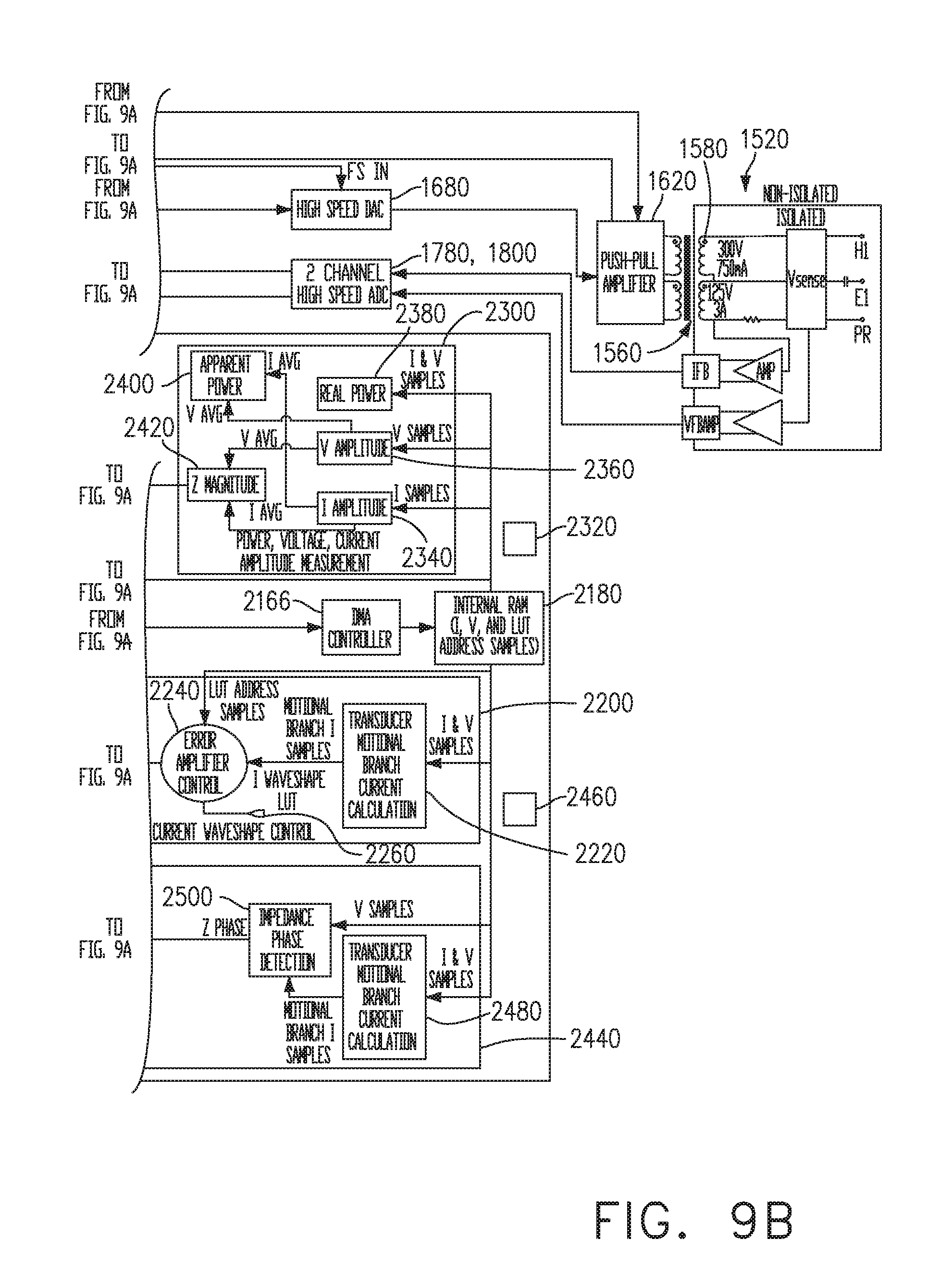
D00013
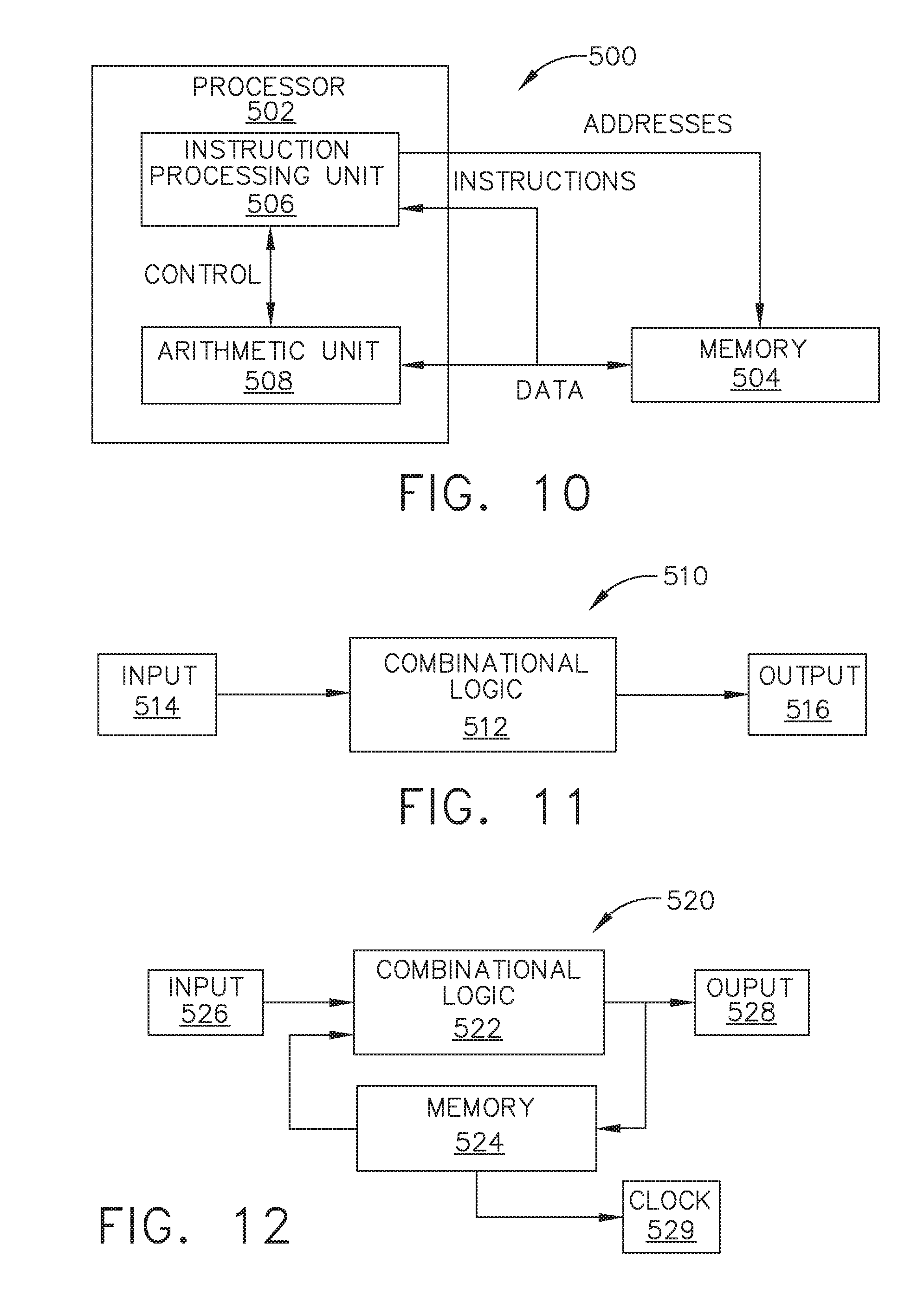
D00014

D00015

D00016

D00017

D00018

D00019

D00020

D00021

D00022

D00023

D00024

D00025

D00026

D00027

D00028


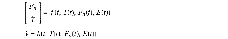


XML
uspto.report is an independent third-party trademark research tool that is not affiliated, endorsed, or sponsored by the United States Patent and Trademark Office (USPTO) or any other governmental organization. The information provided by uspto.report is based on publicly available data at the time of writing and is intended for informational purposes only.
While we strive to provide accurate and up-to-date information, we do not guarantee the accuracy, completeness, reliability, or suitability of the information displayed on this site. The use of this site is at your own risk. Any reliance you place on such information is therefore strictly at your own risk.
All official trademark data, including owner information, should be verified by visiting the official USPTO website at www.uspto.gov. This site is not intended to replace professional legal advice and should not be used as a substitute for consulting with a legal professional who is knowledgeable about trademark law.