Magnetic Field Influence During Rotation Movement Of Magnetic Target
Kozomora; Nevenka ; et al.
U.S. patent application number 15/909208 was filed with the patent office on 2019-09-05 for magnetic field influence during rotation movement of magnetic target. This patent application is currently assigned to Allegro MicroSystems, LLC. The applicant listed for this patent is Allegro MicroSystems, LLC. Invention is credited to Braden Blanchette, Nevenka Kozomora, William Wilkinson.
| Application Number | 20190271568 15/909208 |
| Document ID | / |
| Family ID | 65516783 |
| Filed Date | 2019-09-05 |


| United States Patent Application | 20190271568 |
| Kind Code | A1 |
| Kozomora; Nevenka ; et al. | September 5, 2019 |
Magnetic Field Influence During Rotation Movement Of Magnetic Target
Abstract
A system for reducing stray field effects comprises a magnetic target producing a changing magnetic field; a first set of magnetic field sensing elements placed in spaced relation to the magnetic target and comprising at least a first magnetic field sensing element and a second magnetic field sensing element, each magnetic field sensing element having an axis of maximum sensitivity; a second set of magnetic field sensing elements placed in spaced relation to the magnetic target and comprising at least a third magnetic field sensing element and a fourth magnetic field sensing element, each magnetic field sensing element having an axis of maximum sensitivity; and wherein the first set of magnetic field sensing elements is positioned closer to a center point of the magnetic field than the second set of magnetic field sensing elements.
| Inventors: | Kozomora; Nevenka; (Manchester, NH) ; Wilkinson; William; (Manchester, NH) ; Blanchette; Braden; (Wilton, NH) | ||||||||||
| Applicant: |
|
||||||||||
|---|---|---|---|---|---|---|---|---|---|---|---|
| Assignee: | Allegro MicroSystems, LLC Worcester MA |
||||||||||
| Family ID: | 65516783 | ||||||||||
| Appl. No.: | 15/909208 | ||||||||||
| Filed: | March 1, 2018 |
| Current U.S. Class: | 1/1 |
| Current CPC Class: | G01R 33/072 20130101; G01R 33/091 20130101; G01P 3/487 20130101; G01D 5/16 20130101; G01D 5/142 20130101; G01R 15/207 20130101; G01D 5/145 20130101; G01R 33/098 20130101 |
| International Class: | G01D 5/14 20060101 G01D005/14; G01D 5/16 20060101 G01D005/16 |
Claims
1. A system comprising: a magnetic target producing a rotating magnetic field; a first set of magnetic field sensing elements placed in spaced relation to the magnetic target and comprising at least a first magnetic field sensing element and a second magnetic field sensing element, each magnetic field sensing element having an axis of maximum sensitivity; a second set of magnetic field sensing elements placed in spaced relation to the magnetic target and comprising at least a third magnetic field sensing element and a fourth magnetic field sensing element, each magnetic field sensing element having an axis of maximum sensitivity; and wherein the first set of magnetic field sensing elements is positioned closer to the magnetic target than the second set of magnetic field sensing elements.
2. The system of claim 1 wherein the axes of maximum sensitivity of the magnetic field sensing elements of the first set define a plane and the axes of maximum sensitivity of the magnetic field sensing elements of the second set define a plane.
3. The system of claim 2 wherein the plane defined by the first set and the plane defined by the second set are the same plane.
4. The system of claim 1 wherein: the axis of maximum sensitivity of the first magnetic field sensing element is orthogonal to the axis of maximum sensitivity of the second magnetic field sensing element; and the axis of maximum sensitivity of the third magnetic field sensing element is orthogonal to the axis of maximum sensitivity of the fourth magnetic field sensing element.
5. The system of claim 4 wherein: the axis of maximum sensitivity of the first magnetic field sensing element is parallel to the axis of maximum sensitivity of the third magnetic field sensing element; and the axis of maximum sensitivity of the third magnetic field sensing element is parallel to the axis of maximum sensitivity of the fourth magnetic field sensing element.
6. The system of claim 1 wherein magnetic field sensing elements are placed so that their respective axes of maximum sensitivity are at a respective predetermined angle with respect to the magnetic field.
7. The system of claim 6 wherein: the angle of the axis of maximum sensitivity of the first magnetic field sensing element is about 180 degrees with respect to a centerline defined by the first and second sets of magnetic field sensing elements; the angle of the axis of maximum sensitivity of the second magnetic field sensing element is about 90 degrees with respect to the centerline defined by the first and second sets of magnetic field sensing elements; the angle of the axis of maximum sensitivity of the third magnetic field sensing element is about 180 degrees with respect to the centerline defined by the first and second sets of magnetic field sensing elements; and the angle of the axis of maximum sensitivity of the fourth magnetic field sensing element is about 90 degrees with respect to the centerline defined by the first and second sets of magnetic field sensing elements.
8. The system of claim 1 wherein the magnetic field sensing elements are placed so that their respective axes of maximum sensitivity are at a predetermined angle with respect to an expected direction of a stray magnetic field.
9. The system of claim 8 wherein: the angle of the axis of maximum sensitivity of the first magnetic field sensing element is positioned at a first angle with respect to the expected direction of the stray magnetic field; the angle of the axis of maximum sensitivity of the second magnetic field sensing element is positioned at a second angle to the expected direction of the stray magnetic field; the angle of the axis of maximum sensitivity of the third magnetic field sensing element is positioned at the first angle with respect to the expected direction of the stray magnetic field; and the angle of the axis of maximum sensitivity of the fourth magnetic field sensing element is positioned at the second angle to the expected direction of the stray magnetic field.
10. The system of claim 1 wherein the target comprises a body comprising a cylinder.
11. The system of claim 10 wherein a first half of the cylinder has a first magnetic polarity and a second half of the cylinder has a second magnetic polarity.
12. The system of claim 11 wherein the first and second halves of the cylinder are defined by a plane through which an axis of the cylinder runs.
13. The system of claim 10 wherein the cylinder is defined by four quadrants, where adjacent quadrants have opposite magnetic polarities.
14. The system of claim 1 wherein the target comprises a rod.
15. The system of claim 14 wherein the rod comprises two or more segments having different magnetic polarity.
16. The system of claim 1 wherein each magnetic field sensing element produces an output signal representing the magnetic field as detected by the respective magnetic field sensing element.
17. The system of claim 14 further comprising a processing circuit coupled to receive the output signals of the magnetic field sensing elements and calculate a detected angle of the magnetic field.
18. The system of claim 15 wherein the processing circuit is configured to cancel the effect of a stray magnetic field having a direction substantially orthogonal to a line from the first set to the second set of magnetic field sensing elements.
19. The system of claim 16 wherein the processing circuit includes one or more of: a circuit to perform an arctangent function, a circuit to perform a sin function, and a circuit to perform a cosine function.
20. A system comprising: a magnetic target producing a rotating magnetic field; means for detecting the magnetic field and producing one or more signals representing the magnetic field; means for calculating an angle of the rotating magnetic field from the one or more signals; and means for canceling effects of a stray magnetic field from the calculation of the angle.
21. A system comprising: a magnetic target producing a rotating magnetic field; a first set of magnetic field sensing elements placed in spaced relation to the magnetic target to detect the magnetic field; a second set of magnetic field sensing elements placed in spaced relation to the magnetic target to detect the magnetic field wherein the first set of magnetic field sensing elements is positioned closer to a center point of the magnetic field than the second set of magnetic field sensing elements so that the first set of magnetic field sensing elements detects a stronger magnetic field than the second set of magnetic field sensing elements detects; wherein the first and second set of magnetic field sensing elements are placed so that both sets detect, with approximately equal strength, a stray magnetic field.
22. A system comprising: a magnetic target producing a rotating magnetic field; a first set of magnetic field sensing elements placed in spaced relation to the magnetic target to detect the magnetic field; a second set of magnetic field sensing elements placed in spaced relation to the magnetic target to detect the magnetic field wherein the first set of magnetic field sensing elements is positioned so that the first set of magnetic field sensing elements detects a stronger magnetic field than the second set of magnetic field sensing elements detects; wherein the first and second set of magnetic field sensing elements are placed so that both sets detect, with approximately equal strength, a stray magnetic field.
Description
FIELD
[0001] This disclosure relates to magnetic field sensors and, more particularly, to rejection of stray magnetic fields during detection.
BACKGROUND
[0002] Magnetic field sensors are often used to detect a rotating magnetic target. For example, a magnet may be placed at the end of a rotation shaft, such as a cam shaft or axle. A magnetic field sensor can be placed adjacent to the magnet to detect it as the shaft rotates.
[0003] In some cases, the magnet and sensor are designed to detect an angular position. The magnet may be positioned so that its polarity vector rotates with the shaft. The sensor may be designed to detect the direction of the polarity vector and calculate a positional angle of the magnet.
[0004] Extraneous or stray magnetic fields can make detection of the magnet less accurate and can induce errors in calculating the angle. These fields can be present in the ambient environment or produced by nearby equipment or electronic devices.
SUMMARY
[0005] In an embodiment, a system comprises a magnetic target producing a rotating magnetic field, a first set of magnetic field sensing elements placed in spaced relation to the magnetic target and comprising at least a first magnetic field sensing element and a second magnetic field sensing element, each magnetic field sensing element having an axis of maximum sensitivity and a second set of magnetic field sensing elements placed in spaced relation to the magnetic target and comprising at least a third magnetic field sensing element and a fourth magnetic field sensing element, each magnetic field sensing element having an axis of maximum sensitivity. The first set of magnetic field sensing elements is positioned closer to a center point of the magnetic field than the second set of magnetic field sensing elements.
[0006] One or more of the following features may be included.
[0007] The axes of maximum sensitivity of the magnetic field sensing elements of the first set may define a plane and the axes of maximum sensitivity of the magnetic field sensing elements of the second set may define a plane.
[0008] The plane defined by the first set and the plane defined by the second set may be the same plane.
[0009] The axis of maximum sensitivity of the first magnetic field sensing element may be orthogonal to the axis of maximum sensitivity of the second magnetic field sensing element and the axis of maximum sensitivity of the third magnetic field sensing element may be orthogonal to the axis of maximum sensitivity of the fourth magnetic field sensing element.
[0010] The axis of maximum sensitivity of the first magnetic field sensing element may be parallel to the axis of maximum sensitivity of the third magnetic field sensing element and the axis of maximum sensitivity of the second magnetic field sensing element may be parallel to the axis of maximum sensitivity of the fourth magnetic field sensing element.
[0011] The magnetic field sensing elements may be placed so that their respective axes of maximum sensitivity are at a respective predetermined angle with respect to the magnetic field.
[0012] The rotating magnetic field may have a direction through the first and second sets of magnetic field sensing elements wherein: the angle of the axis of maximum sensitivity of the first magnetic field sensing element is about 180 degrees with respect to a centerline defined by the first and second sets of magnetic field sensing elements; the angle of the axis of maximum sensitivity of the second magnetic field sensing element is about 90 degrees with respect to the centerline defined by the first and second sets of magnetic field sensing elements; the angle of the axis of maximum sensitivity of the third magnetic field sensing element is about 180 degrees with respect to the centerline defined by the first and second sets of magnetic field sensing elements; and the angle of the axis of maximum sensitivity of the fourth magnetic field sensing element is about 90 degrees with respect to the centerline defined by the first and second sets of magnetic field sensing elements.
[0013] The magnetic field sensing elements may be placed so that their respective axes of maximum sensitivity are at a predetermined angle with respect to an expected direction of a stray magnetic field.
[0014] The angle of the axis of maximum sensitivity of the first magnetic field sensing element may be about 90 degrees with respect to the expected direction of the stray magnetic field; the angle of the axis of maximum sensitivity of the second magnetic field sensing element may be about 45 degrees with respect to the expected direction of the stray magnetic field; the angle of the axis of maximum sensitivity of the third magnetic field sensing element may be about 90 degrees with respect to the expected direction of the stray magnetic field; and the angle of the axis of maximum sensitivity of the fourth magnetic field sensing element may be about 45 degrees with respect to the expected direction of the stray magnetic field.
[0015] The target may comprise a body comprising a cylinder.
[0016] A first half of the cylinder may have a first magnetic polarity and a second half of the cylinder may have a second magnetic polarity.
[0017] The first and second halves of the cylinder may be defined by a plane through which an axis of the cylinder runs.
[0018] The cylinder may be defined by four quadrants, where adjacent quadrants have opposite magnetic polarities.
[0019] Each magnetic field sensing element may produce an output signal representing the magnetic field as detected by the respective magnetic field sensing element.
[0020] A processing circuit may be coupled to receive the output signals of the magnetic field sensing elements and calculate a detected angle of the magnetic field.
[0021] The processing circuit may be configured to cancel the effect of a stray magnetic field having a direction substantially orthogonal to a line from the first set to the second set of magnetic field sensing elements.
[0022] The processing circuit may include one or more of: a circuit to perform an arctangent function, a circuit to perform a sin function, and a circuit to perform a cosine function.
[0023] In another embodiment, a system comprises: a magnetic target producing a rotating magnetic field; means for detecting the magnetic field and producing one or more signals representing the magnetic field; means for calculating an angle of the rotating magnetic field from the one or more signals; and means for canceling effects of a stray magnetic field from the calculation of the angle.
[0024] In another embodiment, a system comprises a magnetic target producing a rotating magnetic field; a first set of magnetic field sensing elements placed in spaced relation to the magnetic target to detect the magnetic field; a second set of magnetic field sensing elements placed in spaced relation to the magnetic target to detect the magnetic field wherein the first set of magnetic field sensing elements is positioned closer to a center point of the magnetic field than the second set of magnetic field sensing elements so that the first set of magnetic field sensing elements detects a stronger magnetic field than the second set of magnetic field sensing elements detects; wherein the first and second set of magnetic field sensing elements are placed so that both sets detect, with approximately equal strength, a stray magnetic field.
BRIEF DESCRIPTION OF THE DRAWINGS
[0025] The foregoing features may be more fully understood from the following description of the drawings. The drawings aid in explaining and understanding the disclosed technology. Since it is often impractical or impossible to illustrate and describe every possible embodiment, the provided figures depict one or more exemplary embodiments. Accordingly, the figures are not intended to limit the scope of the invention. Like numbers in the figures denote like elements.
[0026] FIG. 1 is a diagram of a system for detecting a rotating target.
[0027] FIG. 2 is a diagram of a magnetic field sensor and a magnetic target.
[0028] FIG. 2A is a graph of magnetic field strength versus distance.
[0029] FIG. 3 is a diagram of another embodiment of a magnetic field sensor and a magnetic target.
[0030] FIG. 3A is a diagram of another embodiment of a magnetic field sensor and a magnetic target.
[0031] FIG. 3B is a diagram of another embodiment of a magnetic field sensor and a magnetic target.
[0032] FIG. 3C is a diagram of another embodiment of a magnetic field sensor and a magnetic target.
[0033] FIG. 4 is a diagram of another embodiment of a magnetic field sensor and a magnetic target.
[0034] FIG. 5 is a diagram of a magnetic target with a magnetic field sensor.
[0035] FIG. 6 is a diagram of a magnetic target with positioning of a magnetic field sensor.
[0036] FIG. 7 is a diagram of a magnetic field sensor showing a processing circuit, and a magnetic target.
DETAILED DESCRIPTION
[0037] As used herein, the term "magnetic field sensing element" is used to describe a variety of electronic elements that can sense a magnetic field. The magnetic field sensing element can be, but is not limited to, a Hall Effect element, a magnetoresistance element, or a magnetotransistor. As is known, there are different types of Hall Effect elements, for example, a planar Hall element, and a vertical Hall element. As is also known, there are different types of magnetoresistance elements, for example, a semiconductor magnetoresistance element such as Indium Antimonide (InSb), a giant magnetoresistance (GMR) element, an anisotropic magnetoresistance element (AMR), a tunneling magnetoresistance (TMR) element, and a magnetic tunnel junction (MTJ). The magnetic field sensing element may be a single element or, alternatively, may include two or more magnetic field sensing elements arranged in various configurations, e.g., a half bridge or full (Wheatstone) bridge. Depending on the device type and other application requirements, the magnetic field sensing element may be a device made of a type IV semiconductor material such as Silicon (Si) or Germanium (Ge), or a type III-V semiconductor material like Gallium-Arsenide (GaAs) or an Indium compound, e.g., Indium-Antimonide (InSb).
[0038] As is known, some of the above-described magnetic field sensing elements tend to have an axis of maximum sensitivity parallel to a substrate that supports the magnetic field sensing element, and others of the above-described magnetic field sensing elements tend to have an axis of maximum sensitivity perpendicular to a substrate that supports the magnetic field sensing element. In particular, planar Hall elements tend to have axes of sensitivity perpendicular to a substrate, while metal based or metallic magnetoresistance elements (e.g., GMR, TMR, AMR) and vertical Hall elements tend to have axes of sensitivity parallel to a substrate.
[0039] As used herein, the term "magnetic field sensor" is used to describe a circuit that uses a magnetic field sensing element, generally in combination with other circuits. Magnetic field sensors are used in a variety of applications, including, but not limited to, an angle sensor that senses an angle of a direction of a magnetic field, a current sensor that senses a magnetic field generated by a current carried by a current-carrying conductor, a magnetic switch that senses the proximity of a ferromagnetic object, a rotation detector that senses passing ferromagnetic articles, for example, magnetic domains of a ring magnet or a ferromagnetic target (e.g., gear teeth) where the magnetic field sensor is used in combination with a back-biased or other magnet, and a magnetic field sensor that senses a magnetic field density of a magnetic field.
[0040] As used herein, the terms "target" and "magnetic target" are used to describe an object to be sensed or detected by a magnetic field sensor or magnetic field sensing element.
[0041] FIG. 1 shows an example of a system 100 for detecting a magnetic target 102. Target 102 may be placed at the end of rotating shaft 104. In embodiments, rotating shaft may be a cam shaft, an axle, a spindle, a spool, or any type of machine that rotates.
[0042] Magnetic target 102 may be polarized so that it has a north section 106 and a south section 108. In the case of a cylindrical target 102, north section 106 and south section 108 may each comprise a horizontal cylindrical segment of target 102. The polarization of magnet 102 may produce a magnetic field vector in the direction of vector 110.
[0043] A magnetic field sensor 112 may be positioned adjacent to target 102 to detect the magnetic field. As shaft 104 rotates, magnetic field vector 110 may also rotate. Magnetic field sensor 112 may be configured to detect the magnetic field and the angle of its rotation.
[0044] Magnetic field sensor 112 may be communicatively coupled to a processor 114. As an example, if shaft 104 is a camshaft in a vehicle, processor 114 may be an in-vehicle computer that may control the vehicle based, in part, on information provided by sensor 112. As sensor 112 detects the magnetic field, it may send information about the magnetic field (such as position, speed of rotation, phase, angle, etc.) to processor 114. Magnetic field sensor 112 may also communicate information about any errors encountered to processor 114.
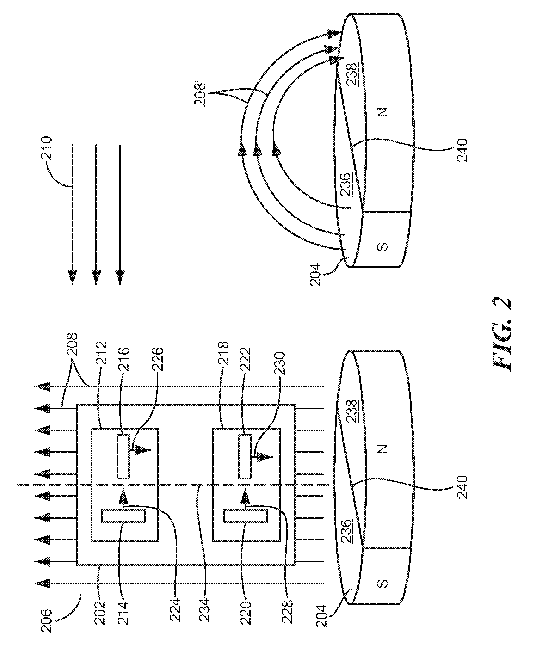
[0045] Referring to FIG. 2, a system 200 includes a magnetic field sensor 202, which may be the same as or similar to magnetic field sensor 112, and a target 204, which may be the same as or similar to target 102. Target 204 may produce magnetic field 206. For ease of illustration, magnetic field 206 produced by target 204 is illustrated by straight magnetic field lines 208. However, the direction of magnetic field 206 may be different from that shown by magnetic field lines 208. For example, magnetic field lines 208' may present a more realistic depiction of a magnetic field produced by target 204. One skilled in the art will recognize that, throughout the figures, magnetic fields may be drawn with straight lines for ease of illustration, but may take other shapes, forms, and directions depending on the type and shape of the magnetic source. Even though a magnetic field is drawn in the figures using straight lines, it does not necessarily indicate that the magnetic field has uniform field strength along those lines, unless specifically described as uniform in the text. For example, the magnetic field depicted by magnetic field lines 208 will have greater strength (e.g. flux density) around pair 218 (closer to target 204) and relatively weaker strength around pair 212 (further away from target 204).
[0046] Magnetic field sensor 202 may be positioned adjacent to target 204 to detect magnetic field 206 as target 204 rotates and compute an angle of rotation of target 204. Magnetic field lines 210 represent an external, or stray, magnetic field that can influence detection of magnetic field 206 by sensor 202 and potentially cause errors or inaccuracies.
[0047] In embodiments, magnetic field sensor 202 may include a first set 212 of magnetic field sensing elements 214 and 216, and a second set 218 of magnetic field sensing elements 220 and 222. Each set may contain a pair of magnetic field sensing elements. In other embodiments, each set may contain more than two magnetic field sensing elements.
[0048] Magnetic field sensing element 202 may be positioned so that set 218 is closer to target 204 than set 212. Thus, magnetic field sensing elements 220 and 222 may be subject to and detect a stronger magnetic field 206 than that which is detected by magnetic field sensing elements 214 and 216.
[0049] Magnetic field 210 may be a uniform magnetic field that affects magnetic field sensing elements 220, 222, 214, and 216 substantially equally. Thus, in contrast to magnetic field 208, magnetic fields sensing elements 220, 222, 216, and 216 may be subject to and detect a substantially equal stray magnetic field 210.
[0050] Each magnetic field sensing element 214, 216, 220, and 222 has an axis of maximum sensitivity (as described above) represented by arrows 224, 226, 228, and 230, respectively. The axes of maximum sensitivity 224 and 226 may be viewed as non-parallel vectors and thus may define a first plane. Similarly, the axes of maximum sensitivity 228 and 23o may be viewed as non-parallel vectors and thus may define a second plane. In embodiments, the first and second planes may be the same (or substantially the same) plane as shown in FIG. Magnetic field sensing elements 214, 216, 228, and 230 may be placed within the plane formed by the axes of maximum sensitivities, with set 212 of magnetic field sensing elements 214 and 216 being further away from target 204 than set 218 of magnetic field sensing elements 220 and 222.
[0051] In embodiments, axis of maximum sensitivity 224 of magnetic field sensing element 214 is orthogonal to axis of maximum sensitivity 226 of magnetic field sensing element 216, and the axis of maximum sensitivity 228 of magnetic field sensing element 220 is orthogonal to the axis of maximum sensitivity 230 of magnetic field sensing element 222.
[0052] As shown in FIG. 2, axes of maximum sensitivity 224 and 226 form a ninety-degree angle with each other. In an embodiment, magnetic field sensing elements 214 and 216 may also be placed so that their respective axes of maximum sensitivity form a forty-five degree angle with respect to magnetic field 206. Similarly, axes of maximum sensitivity 228 and 230 form a ninety-degree angle with each other. In an embodiment, magnetic field sensing elements 220 and 222 may also be placed so that their respective axes of maximum sensitivity form a forty-five-degree angle with respect to magnetic field 206.
[0053] One skilled in the art will recognize that the respective angle formed by the axes of maximum sensitivity 224, 226, 228, and 230 may be described with various coordinate systems. For example, using an angular coordinate system 232 and assuming centerline 234 is parallel to the expected direction of magnetic field 206, the angle between axis of maximum sensitivity 226 and centerline 234 is about 180 degrees; the angle between axis of maximum sensitivity 224 and centerline 234 is about 90 degrees; the angle between the axis of maximum sensitivity 230 and centerline 234 is about 180 degrees; and the angle between axis of maximum sensitivity 228 and centerline 234 is about 90 degrees with respect to centerline 234.
[0054] As noted above, stray magnetic field 210 may have an expected direction that is orthogonal to magnetic field 206. Thus, in one example, the magnetic field sensing elements may be placed so that the angle between axis of maximum sensitivity 226 and stray magnetic field 210 may be 90 degrees; the angle between axis of maximum sensitivity 224 and stray magnetic field 210 may be 45 degrees; the angle between axis of maximum sensitivity 230 and stray magnetic field 210 may be 90 degrees; and the angle between axis of maximum sensitivity 228 and stray magnetic field 210 may be 45 degrees.
[0055] Target 204 may be a cylindrical, rotating target. In some instances, target 204 may be an end-of-shaft magnetic target that may be placed on the end of a rotating shaft. Target 204 may comprise two horizontal cylindrical segments 236 and 238 formed by a plane (represented by line 240) that runs parallel to and through the cylinders axis of symmetry. Segments 236 and 238 may have opposite magnetic polarity--magnetic south for segment 236 and magnetic north for segment 238, for example.
[0056] As target 204 rotates, so does magnetic field 206. Each magnetic field sensing element 214, 216, 220, and 222 may detect magnetic field 206 and produce an output signal representing magnetic field 206 as detected by the respective magnetic field sensing element.
[0057] The positioning of the pairs 212 and 218 may allow magnetic field sensor 202 to detect magnetic field 206 while reducing interference or errors from stray field 210. For example, because set 212 is further from target 204 than is set 218, set 212 may detect a weaker magnetic field 206 than that detected by set 218.
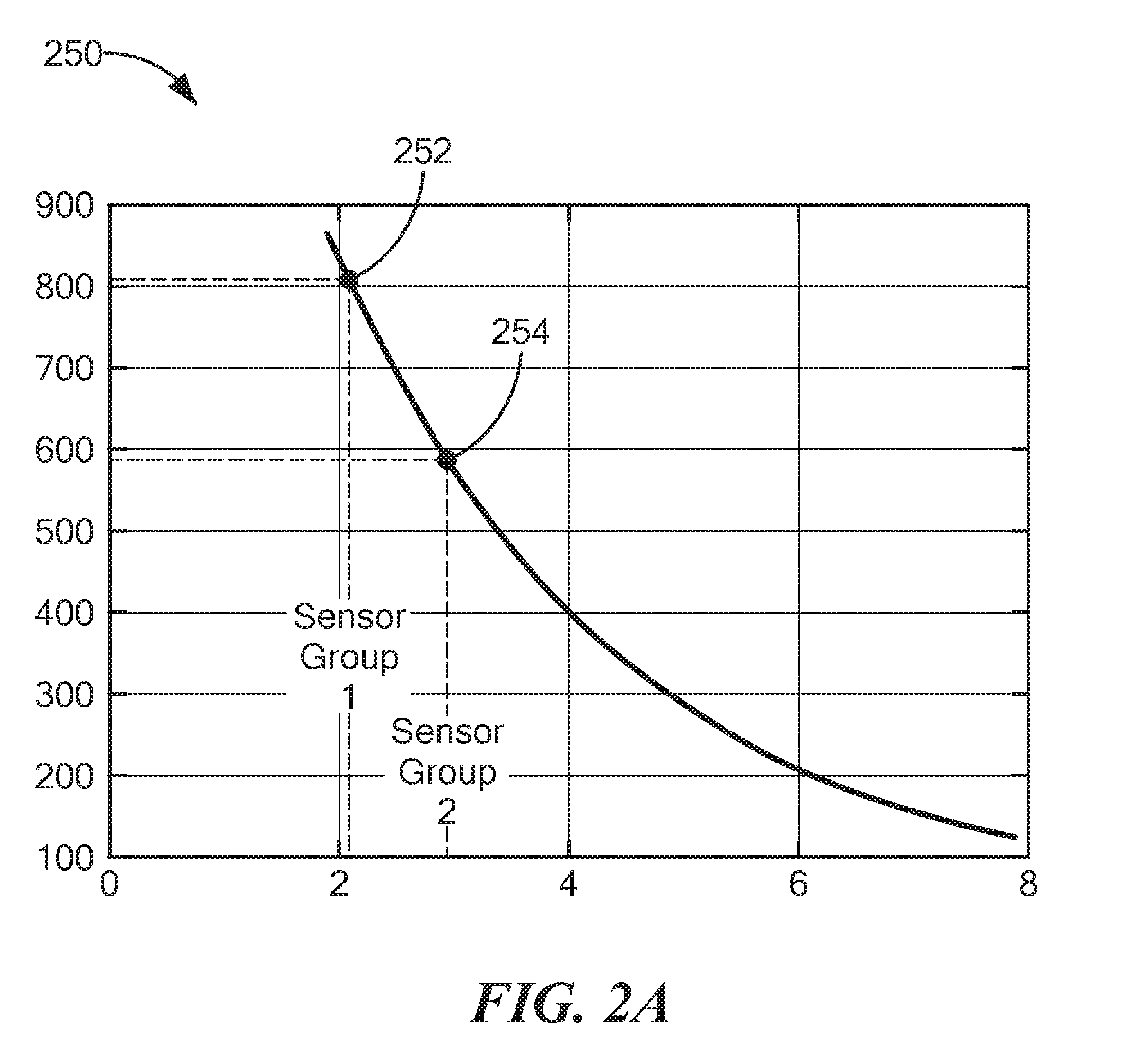
[0058] Referring to FIG. 2A, graph 250 illustrates the difference in magnetic field strength experienced by the pairs of magnetic field sensing elements. In graph 250, the horizontal axis represents distance between the magnetic field sensing element and the target, and the vertical axis represents the magnetic field as detected by a magnetic field sensing element. If set 218 is placed at a distance of about 2 mm from the target, it may experience 800 Gauss of field strength, according to point 252. If set 212 is placed at a distance of about 3 mm from the target, it may experience 600 Gauss of field strength, according to point 254.
[0059] The field strength difference may also be detected by magnetic field sensing elements placed in two 3D sensing groups. These groups may be in the same die, or on different die, so long as their respective spacing from the target is maintained. If they are placed on the same die, the die may be positioned perpendicular to the target so that one group (or set) of magnetic field sensing elements is further from the target than the other.
[0060] Referring again to FIG. 2, in embodiments, magnetic field 210 may be a substantially uniform magnetic field. Thus, set 212 and set 218 may detect magnetic field 210 with the same magnitude or strength. A processor (such as processor 114 in FIG. 1) may receive the outputs from each set 212 and 218 and use the varying magnetic field strengths detected by pairs 212 and 218 to calculate an angle of magnetic field 206 while reducing or minimizing the effect that magnetic field 210 has on the calculation.
[0061] Referring to FIG. 3, in an embodiment, system 200' may include magnetic field sensor 202 and target 240 arranged so that magnetic field sensor 202 is orthogonal to the cylindrical (e.g. center) axis of target 240. In this embodiment, the cylindrical axis of target 240 may perpendicular (into and out of) the page. Magnetic field sensor 202 may be arranged so that set 218 is closer to target 240 (i.e. closer to the central axis) than is set 212. In this embodiment, the stray field may have an expected direction orthogonal to magnetic field 206 (i.e. an expected direction into or out of the page). In other embodiments, the stray field may have an expected direction along the plane of the page, similar to that of stray magnetic field 210 shown in FIG. 2.
[0062] In this arrangement, magnetic field sensing element 212 may be positioned further away that magnetic field sensing element pair 218 from target 240. In an embodiment, magnetic field sensing element pair 212, magnetic field sensing element pair 218, and target 240 may be arranged in a line. The strength of magnetic field 206 may be greater closer to target 240 and relatively weaker further away from target 240. As a result, magnetic field sensing element pair 218 may detect a stronger magnetic field than magnetic field sensing element pair 212.
[0063] Referring to FIG. 3A, system 200'' may include magnetic field sensor 202' having magnetic field sensing element pair 212' and magnetic field sensing element pair 218'. Magnetic field sensor 202' may be positioned so that a line 302 drawn through the center of pair 212' and pair 218' is substantially perpendicular to a line 304 drawn through the center 306 of magnetic field sensor 202' and the center 308 of target 240.
[0064] In embodiments, target 240 may rotate about an axis of rotation that passes through center point 308 and goes into and out of the page. In other words, target 240 may rotate in a clockwise and/or counterclockwise direction, as shown by arrow 310, about center point 308.
[0065] As target 240 rotates, the magnetic field 206 it produces also rotates about the axis of rotation. As magnetic field 206 rotates past magnetic field sensing element pairs 212' and 218', the magnetic field sensing elements will detect changes in the magnetic field due to its rotation. Assume that magnetic field 206 is rotating in a counterclockwise direction. Magnetic field sensing element pair 218' may detect a particular level or a particular change in magnetic field 206 before magnetic field sensing element pair 212' does. Thus, an output signal from magnetic field sensing element pair 218' may reflect the particular change or level before an output signal from magnetic field sensing element pair 212' does. In other words, in this arrangement, there may be a phase difference between the output signals of the magnetic field sensing elements of pair 218' and the magnetic field sensing elements of pair 212'. This phase difference may be used to detect speed of rotation, direction of rotation, position of target 240, etc.
[0066] Referring to FIG. 3B, in an embodiment, system 300B may include magnetic field sensor 312 and target 314. Target 314 may be a cylindrical or flat rod-shaped target configured to move back and/or forth along line 316 as shown by arrow 318. Target 314 may include a magnetic north segment 320 directly adjacent to a magnetic south segment 322. Although two segments 320, 322 are shown, target 314 may include additional segments coupled together so that adjacent segments have opposite magnetic poles. In embodiments, target 314 may have one or more non-magnetic segments adjacent to magnetic segments. The magnetic segments surrounding a non-magnetic segment may have opposite magnetic poles or the same magnetic poles.
[0067] Magnetic field sensor 312 may include a first pair 324 of magnetic field sensing elements and a second pair 326 of magnetic field sensing elements. Magnetic field sensor 312 may arranged so that a line drawn from the center of pair 326 to the center of pair 324 is substantially perpendicular to the line of travel 316 of target 314. Pair 324 may be closer than pair 326 to target 314. As a result, the magnetic field sensing elements of pair 324 may detect a stronger magnetic field than the magnetic field sensing elements of pair 326.
[0068] Referring to FIG. 3C, in an embodiment, system 300C may include magnetic field sensor 328 and target 314. Target 314 may be a cylindrical or flat rod-shaped target configured to move back and/or forth along line 316 as shown by arrow 318. Target 314 may include a magnetic north segment 320 directly adjacent to a magnetic south segment 322. Although two segments 320, 322 are shown, target 314 may include additional segments coupled together so that adjacent segments have opposite magnetic poles. In embodiments, target 314 may have one or more non-magnetic segments adjacent to magnetic segments. The magnetic segments surrounding a non-magnetic segment may have opposite magnetic poles or the same magnetic poles.
[0069] Magnetic field sensor 328 may include a first pair 330 of magnetic field sensing elements and a second pair 332 of magnetic field sensing elements. Magnetic field sensor 328 may arranged so that a line 334 drawn from the center of pair 330 to the center of pair 332 is substantially parallel to the line of travel 316 of target 314.
[0070] In embodiments, target 314 may move translationally in the directions indicated by arrow 318. As target 314 moves, the magnetic field it produces also moves. As the magnetic field moves past or through magnetic field sensing element pairs 330 and 332, the magnetic field sensing elements will detect changes in the magnetic field due to its movement. Assume that target 314 is moving in a left-to-right direction on the page. Magnetic field sensing element pair 330 may detect a particular level or a particular change in the magnetic field before magnetic field sensing element pair 332 does. Thus, an output signal from magnetic field sensing element pair 330 may reflect the particular change or level before an output signal from magnetic field sensing element pair 332 does. In other words, in this arrangement, there may be a phase difference between the output signals of the magnetic field sensing elements of pair 330 and the magnetic field sensing elements of pair 332. This phase difference may be used to detect speed of rotation, direction of rotation, position of target 314, etc.
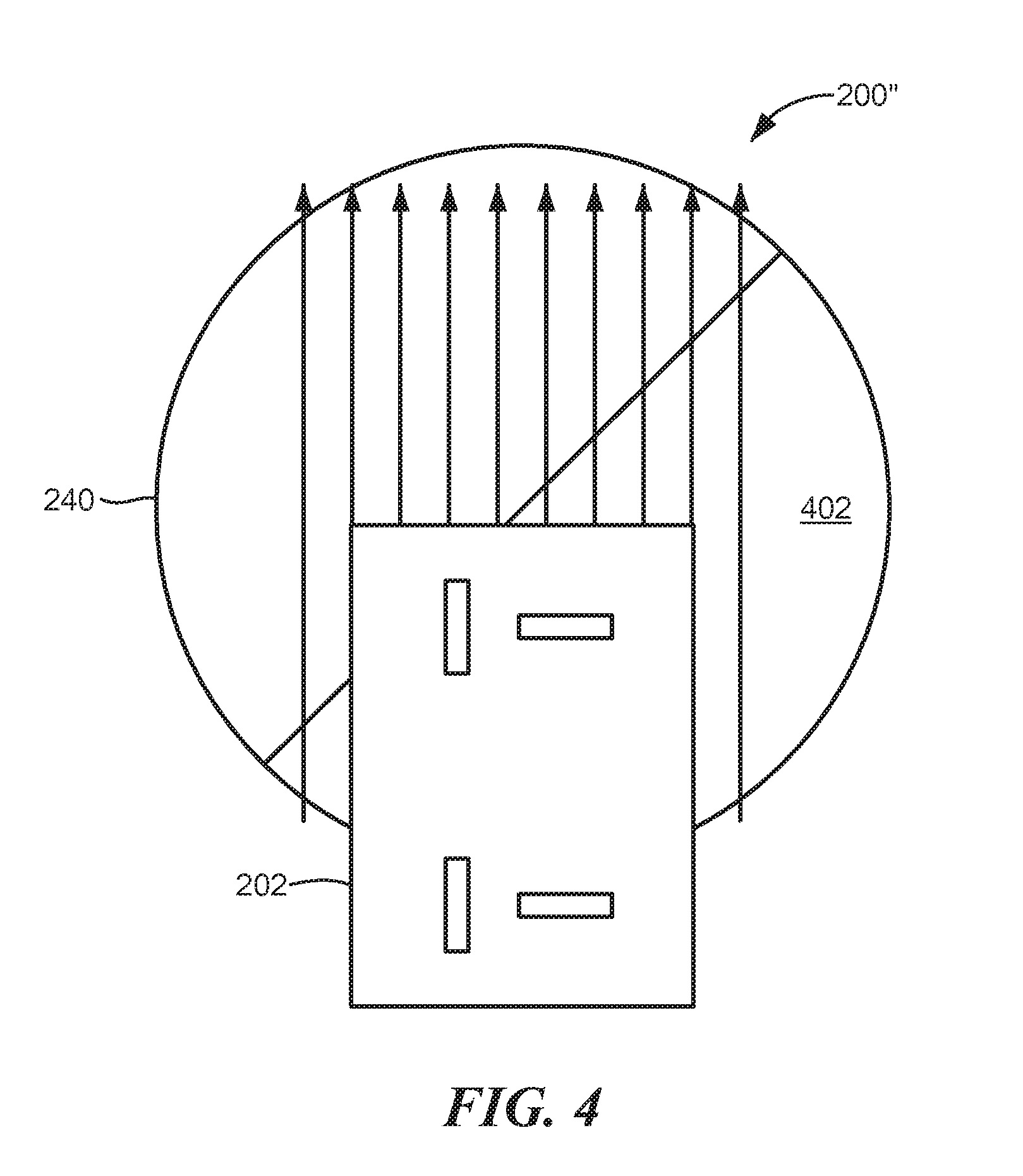
[0071] Referring to FIG. 4, in an embodiment, system 200'' may include magnetic field sensor 202 and target 240 arranged so that magnetic field sensor 202 overlaps a flat surface 402 of target 202. In other embodiments, magnetic field sensor may be offset from the center of target 240.
[0072] Referring to FIG. 5, system 500 may include a magnetic field sensor 502, which may be the same as or similar to magnetic field sensor 202. Magnetic field sensor 502 may be placed adjacent to target 504 to detect a magnetic field produced by target 504.
[0073] Target 504 may comprise four quadrants 506-512. Each adjacent quadrant may have opposite magnetic polarities. For example, quadrant 506 and 508 may be adjacent because they share an edge 514. Thus, quadrant 506 may have a south polarity and quadrant 508 may have a north polarity. Quadrant 508 and 512 may be adjacent because they share an edge 516. Thus, quadrant 512 may have a south polarity and quadrant 508 may have a north polarity. Quadrant 510 may have a north polarity and share edges with south polarity quadrants 506 and 512.
[0074] The four quadrants 506-512 may produce a magnetic field with a direction, in part, that is substantially parallel to the top surface of target 504 as shown, for example, by magnetic field lines 520. Magnetic field sensor 502 may be offset from the center of target 504 to detect the magnetic field produced by target 504 as target 504 rotates. In another embodiment, magnetic field sensor 502 may be positioned adjacent to the circumference of target 504.
[0075] Referring to FIG. 6, the magnetic field sensor may be centered in position 602 over target 504, or may be offset, as shown by positions 604. As noted above, the magnetic field sensor may have two (or more) pairs or sets of magnetic field sensing elements. (See set 212 and set 218 in FIG. 2). In embodiments, one set of magnetic field sensing elements may be positioned closer to the center of target 504 at, for example, position 602. The other set of magnetic field sensing elements may be further offset from the center of target 504 at, for example, one of the positions 604. Separation of the sets of magnetic field sensing elements may result in one set detecting a stronger magnetic field from target 504 and the other set detecting a weaker magnetic field from target 504. The difference in detected field strength may be utilized to reject stray magnetic fields, as described above.
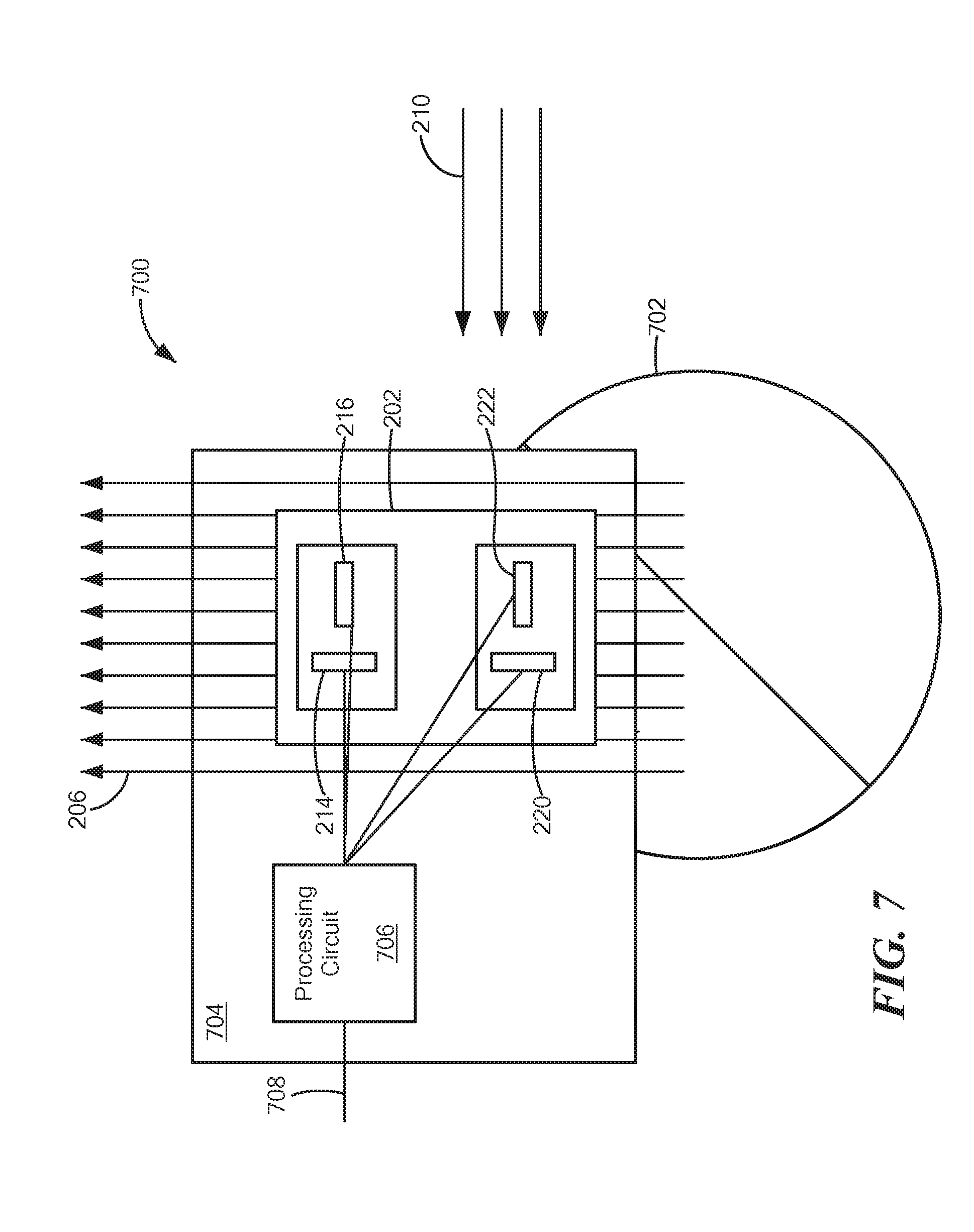
[0076] Referring to FIG. 7, system 700 may include magnetic field sensor 202 and target 702. Target 702 may be the same as or similar to target 204 or 504. System 700 may also include a substrate 704, which may be a semiconductor substrate, and which may support processing circuit 706 (e.g. processing circuit 706 may be formed in and/or on substrate 704). Substrate 704 may also support magnetic field sensor 202 and magnetic field sensing elements 214, 216, 220, 222.
[0077] Processing circuit 706 may include circuitry to receive signals from magnetic field sensing elements 214, 216, 220, 222, which represent detection of magnetic field 206, and may calculate an angle of rotation of magnetic field 206, a speed of rotation of magnetic field 206, etc. To perform the calculation, processing circuit 706 may include custom circuitry and/or processor executing software or firmware code that calculates the angle of the magnetic field. Processing circuit 706 may also generate an output signal 708 representing the computed angle, speed, etc.
[0078] Immunity to stray field 210 may be accomplished by utilizing the varying levels of signal intensity from the magnetic field sensing elements. As noted above, magnetic field sensing elements 220 and 222 may detect a stronger magnetic field 206 than magnetic field sensing elements 214 and 216 detect, because magnetic field sensing elements 220 and 222 may be closer to target 702.
[0079] Processor 706 may use the following equations to compute the detected magnetic field:
H1y=AB.sub.1 sin .theta..sub.B+AB.sub.stray sin .theta..sub.stray (1)
H1x=AB.sub.1 cos .theta..sub.B+AB.sub.stray cos .theta..sub.stray (2)
H2y=AkB.sub.1 sin .theta..sub.B+AB.sub.stray sin .theta..sub.stray (3)
H2x=AkB.sub.1 cos .theta..sub.B+AB.sub.stray cos .theta..sub.stray (4)
In the equations above, H1y is the output signal of magnetic field sensing element 216, H1x is the output signal of magnetic field sensing element 214, H2y is the output of magnetic field sensing element 222, H2x is the output of magnetic field sensing element 222, A is a scalar sensitivity factor of the magnetic field sensing elements, B.sub.1 is magnetic field 206, B.sub.stray is stray magnetic field 210, and k is a scaling factor representing the difference in magnetic field strength as detected by set 212 and set 218 (see FIG. 2).
[0080] Subtracting equations 4 from 1 and 3 from 2 removes the effect of the stray field and reduces the equations to the following:
Hydiff=(1-k)AB.sub.1 sin .theta..sub.B (5)
Hxdiff=(1-k)AB.sub.1 cos .theta..sub.B (6)
The angle of rotation of the magnetic field can be calculated with the following formula:
.theta. B = arctan ( Hydiff Hxdiff ) ( 7 ) ##EQU00001##
Processing circuit 706 may provide the signal .theta..sub.B as output signal 708.
[0081] Having described preferred embodiments, which serve to illustrate various concepts, structures and techniques, which are the subject of this patent, it will now become apparent to those of ordinary skill in the art that other embodiments incorporating these concepts, structures and techniques may be used. Accordingly, it is submitted that that scope of the patent should not be limited to the described embodiments but rather should be limited only by the spirit and scope of the following claims. All references cited in this disclosure are incorporated here by reference in their entirety.
* * * * *
D00000
D00001
D00002
D00003
D00004
D00005
D00006
D00007
D00008
XML
uspto.report is an independent third-party trademark research tool that is not affiliated, endorsed, or sponsored by the United States Patent and Trademark Office (USPTO) or any other governmental organization. The information provided by uspto.report is based on publicly available data at the time of writing and is intended for informational purposes only.
While we strive to provide accurate and up-to-date information, we do not guarantee the accuracy, completeness, reliability, or suitability of the information displayed on this site. The use of this site is at your own risk. Any reliance you place on such information is therefore strictly at your own risk.
All official trademark data, including owner information, should be verified by visiting the official USPTO website at www.uspto.gov. This site is not intended to replace professional legal advice and should not be used as a substitute for consulting with a legal professional who is knowledgeable about trademark law.